Flow Structure for a Circular Cylinder with Exterior Surface Dimples
Jongmyung Park
1)and Chi-Ho Yoon
1)*외부 표면 딤플을 갖는 원형실린더의 유동구조
박종명· 윤치호*
요 약 : 항력을 감소시키기 위하여, 심해저 채광을 위한 라이저 형태의 양광관 외부표면에 딤플구조를 사용하 였다. 양광관(원형실린더) 주위의 유체유동을 FLUENT 버전 6.3.26을 이용하여 예측하였다. 수치 해석은 3가지 경우에서 수행하였으며, Case 1은 딤플내에서 운동량 이송의 증가를 보여주었고, Case 2는 수치해석의 타당성 및 원형실린더 주위의 유동구조를 제시하였다. Case 3에서는 실린더 딤플 내에서의 유동구조를 분석하였다.
심해저 망간간괴를 양광하는 파이프 외벽의 딤플구조는 본 연구에서는 원형의 중간형태의 딤플(딤플 깊이/딤플 프린트 지름 = 0.2)을 사용하였으며, 이 딤플은 원형실린더 외벽에 위치한 형태이다. 이 연구에 제시된 새로운 디자인의 딤플실린더는 원형의 실린더보다 낮은 항력계수를 보여주었고 딤플내의 속도 분포를 제시하였다.
이 결과는 저항력의 새로운 양광관 및 유연관 설계에 활용할 수 있을 것이다.
주요어 : 라이저, 원형실린더, 딤플 실린더, 항력계수, 항력 감소
Abstract : Dimples are employed on the exterior surface of the lifting pipe which is in the shape of a riser for reduction of drag forces. Water flow around a lifting pipe (circular cylinder) with exterior surface dimples is numerically predicted using version 6.3.26 of FLUENT. This numerical simulation is conducted in 3 cases.
Case 1 shows the increases of momentum transportation in the dimple. Case 2 presents the validation of this simulation and the flow structure around the cylinder. And the flow structure in the dimple of the cylinder is investigated in Case 3. Spherical medium dimples (the dimple depth/the dimple print diameter=0.2) are located on the exterior of a circular cylinder. The new design presented in this research shows the lower drag coefficient of a dimpled cylinder compared to the data of a circular bare cylinder and velocity distribution is investigated in the dimple. This result is applied for design of the new lifting pipes and flexible hoses.
Key words : Riser, Circular cylinder, Dimpled cylinder, Drag coefficient, Drag reduction
2009년 9월 21일 접수, 2010년 2월 17일 채택 1) 한국지질자원연구원
*Corresponding Author(윤치호) E-mail; [email protected]
Address; Korea Institute of Geoscience and Mineral Resources, 30, Gajeong-dong, Yuseong-gu, Daejeon, 305-350, Korea
Introduction
The deep-sea mining system is comprised of three different parts : seafloor collecting system, lifting system and a mining ship (Chung, 1994). The lifting system is employed for lifting manganese nodules from the seabed to the mining ship. This lifting system is a set of devices, for example, hydraulic pumps, lifting pipes, a buffer and flexible hoses. The cross-section of the lifting pipes
usually is circular. The flow of sea water makes the pipes vibrate, which results in additional problems and technical difficulties. The reduction of drag of theses cylinders is one solution for this vibration problem. Drag is the force on the body opposite to the moving direction. This amount of drag is determined by the location of separation points of flow along the body. For reduction of drag, it is important to move the separation point of flow backward.
Many researches presented the new design of the cylinder with cables and fairings to change the separation point of flow. The design of a circular cylinder with exterior surface dimples is first presented in this paper and one of the purposes of this study is to investigate the flow structure in the dimple of the cylinder.
Of the recent investigations that research flow structure characteristics over a cylinder and dimples, Chung et 연구논문
al. (1994) present the means of reducing vortex-shedding- induced vibration of a deep-ocean mining pipe of 6000 m in length and the measurement of flow-induced torsional moment of the pipe. Five basic configurations are experi- mented: bare cylinder, cylinder with perforated shroud, cylinder with straight two cables and strakes, cylinder with straight three cables and strakes, and cylinder with strakes. According to these investigators, the strake model with electromagnetic (EM) power cables and a cylinder model with a perforated shroud show the least vortex- shedding intensity and minimum increase in drag. Bearman et al. (1993) report the drag coefficient and the Strouhal number of a dimpled circular cylinder over the Reynolds number of 2×10⁴ to 3×10⁵. The ratio of the depth of the dimples to the dimple print diameter is 9×10⁻³. The authors describe that a dimpled circular cylinder has a lower drag coefficient than a smooth cylinder over the Reynolds number of 4×10⁴ to 3×10⁵.
Kimura et al. (1991) show a groove on the circular cylinder moves the separation point backward and reduces drag even at low Reynolds number. Three types of grooves (depth of dimple/dimple print diameter = 0.21, 0.15, and 0.09) are studied. The most effective positions of the grooves are about 80º measured from the foremost point of the cylinder, according to the authors.
For the study of flow structure due to dimple de- pressions on a flat plate, Ligrani et al. (2001) presents instantaneous, dynamic and time-averaged characteristics of the vortex structures above and from the dimples on one wall of a channel. Flow visualization images and the experiment data are given. The primary vortex and secondary vortex pairs augment the normalized Reynolds normal stress (u′2/U2). Sherrow et al. (2006) presented the effects of adding spherical-indentation dimples to the exterior surfaces of tubes in a crossflow heat exchanger. The ratio of the dimple depth to the dimple print diameter is 0.1 and 0.4. Significant heat transfer augmentations are reported.
The numerical solutions presented in this article provide additional information on flow structure in a 3-D dimpled channel surface, a 2-D pure cylinder, and a 2-D dimpled cylinder.
Numerical Procedures
The FLUENT numerical code, version 6.3.26 (called
“PROGRAM” in this paper) is employed for all numerical simulations. GAMBIT 2.3.16 is used for the numerical grid.
Turbulence modeling
The realizable k-ε model is employed as the turbulence model, because of its improved prediction compared to the standard k-ε model, and because of its ability to resolve portions of complex flows located very close to the surfaces. This model ensures that the turbulent normal stresses are always positive, which is consistent with the physics of complex turbulent flows. With this scheme, the Reynolds-averaged Navier-Stokes equations are solved numerically, in conjunction with transport equations for the turbulent kinetic energy and dissipation rate. Continuity is satisfied using a semi-implicit method for pressure- linked equations, which is referred to as the SIMPLE procedures. To reduce numerical errors, second-order spatial discretization schemes are used in the calculations.
Solution convergence
Each computation iteration is solved implicitly. The convergence of the computational solution is determined based on scaled residuals, which are set to 10-3. The solution is considered to be converged when all of the scaled residuals are less than or equal to these default settings. Less than 200 iterations are generally needed for convergence.
Basic equations
The continuity equation for phase q is 0
) v t +∇⋅(ρ =
∂ ρ
∂
(1)
Where, ρ is the density and v is the velocity.
The momentum balance for phase q is )
v v ( ) v
t(ρ +∇⋅ρ =
∂
∂ −∇p+∇⋅τ+ρg+F
(2)
where, p is the pressure, τ is the stress-strain tensor, ρg is the gravitational body force, and F is the external body forces.
⎥⎦⎤
⎢⎣⎡∇ +∇ − ∇⋅ μ
=
τ vI
3 ) 2 v v
( r rT rq
(3)
Fig. 1. Schematic diagram of one dimpled side in a channel.
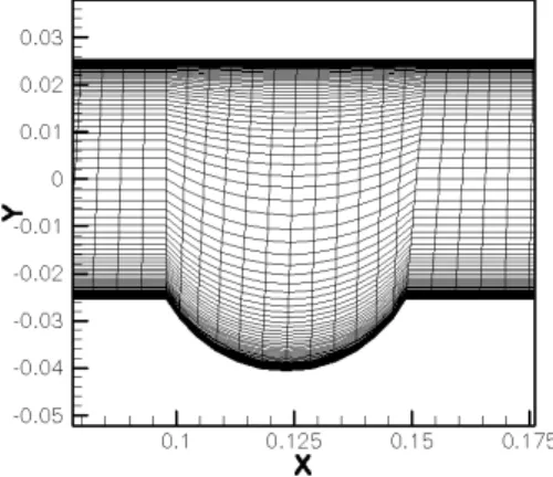
Fig. 2. Computational grid for the dimpled side of the channel.
Fig. 3. 3-D view of velocity vectors near the surface of the central dimple.
Fig. 4. Distribution of the streamwise vorticity in the spanwise-normal plane located after the dimple.
Here I is the unit tensor and μ is the viscosity.
Numerical Results
3 cases are numerically predicted. Case 1 is a dimpled surface on the flat plate to verify the flow structure within the dimples. Case 2 is a two-dimensional circular cylinder.
Case 3 is a two-dimensional circular cylinder with dimples.
The result of case 1 shows the multiple pairs of vortices, which augment local, three-dimensional turbulent transport.
Case 2 is for the validation of PROGRAM in dimples case. Case 3 shows two-dimensional flow structure over the dimple on the surface of a circular cylinder.
Case 1 : Dimpled surface on the flat plate in a rec- tangular duct
Figure 1 shows the schematic diagram of the test surface.
The one dimpled wall has 7 rows of spherical indentation dimples in staggered array. The channel height and dimple print diameter are both 0.0508 m, and the dimple depth
is 0.01524 m. The ratio of dimple depth to dimple print diameter is 0.3. The hydraulic diameter of the channel is 0.0942 m. A 1.2 m long section of smooth and undimpled channel is positioned upstream of the dimpled channel.
This arrangement is the same as the one employed for experimental studies by Burgess et al. (2003).
The inlet velocity is 4.43 m/s and the turbulent intensity is 0.5%. The energy equation is not solved. The compu- tational grid is shown in Figure 2. This portion of the computational grid is employed for the dimpled part of the channel. After this dimple, an array of dimples are followed. Near wall and dimpled surface are meshed with fine grids to resolve the high gradients encountered in this region.
Figure 3 shows 3-D view of velocity vectors near the surface of the dimple. The fluid flows from the left side to the right side. The flow in the dimple includes the recirculation portion. It means the region for the shear layer attachment exists near the downstream edge of the dimple.
10D 40D
20D
20D
Inlet outlet
Wall
Wall
Fig. 5. Schematic diagram of 2-D circular cylinder.
(a)
(b)
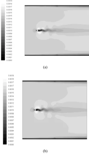
Fig. 6. Velocity magnitude (a) at time = 6950 s (b) at time=7680 s.
Figure 4 presents the distribution of the streamwise vorticity in the spanwise-normal plane located after one dimple. Several augmented streamwise vortices are present near the surface in the immediate vicinity of individual dimples. The central vortex pair starts at the recirculation portion in the dimple and develops outside of each dimple.
This is due to ejection of flow from the dimple.
Array of dimples eject multiple pairs of vortices, which increase local, three-dimensional turbulence transport and secondary advection as they flow downstream.
Case 2 : Two-dimensional circular cylinder
Figure 5 shows a schematic diagram of 2-D circular cylinder for validation of this investigation. The cylinder is a center circle of this figure and the flow field around the cylinder is a rectangular domain. The inlet velocity is uniform. For Re=150, the laminar flow is numerically solved. Water is used as the working fluid with a constant viscosity and a constant density.
Figure 6 presents the picture of velocity magnitude at time =6950 s and 7690 s. Flow over a circular cylinder is changed into the weak vortex street in the wake.
The drag coefficient is defined as follows.
A 2 u 1 C F
2 0 D
D ρ
=
(4) ρ is the density of water and u0 is the free-stream
velocity. A is the projected area. FD is the drag force.
According to White (1986), the drag coefficient for Re=
150 is about 1.3. The value of the drag coefficient in this simulation is about 1.26 and is close to the experi- mental value of 1.3 in White’s experiment. This simula- tion is for confirmation of the cylinder flow. This cylinder flow should show the unsteady vortex shedding in the wake of the flow. Simulated results in the Fig. 6 refer to the creation and shedding of the vortex.
Case 3 : 2-D circular cylinder with dimples This case includes the numerical result of the 2-D circular cylinder with dimples.
This arrangement is the same as the one employed for case 2. But the a 2-D cylinder has dimples on the surface.
300
r=0.725 cm D=1 cm
h=0.2 cm
Fig. 7. Schematic diagram of a dimple cylinder and details of the dimple.
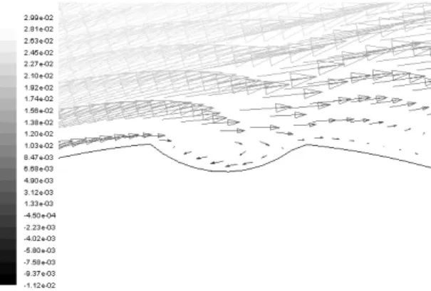
Fig. 8. Velocity vector in streamwise direction within the top dimple.
The length of the inlet is 40 times of the diameter of a cylinder. The Reynolds number is 2000, which is in the range of laminar. All 12 dimples are employed on the surface of a cylinder. Each dimple has a radial offset 30° relative to the adjacent dimples. The ratio of the depth of the dimple to the dimple print diameter is 0.2, because the ratio of 0.2 is expected to have some advantage related to pressure drop than the ratio of 0.3. Figure 7 presents a schematic diagram of a dimple cylinder and details of the dimple. 2-D sectional view of the cylinder with dimples and individual dimple geometry details are shown in this figure. The dimple print diameter is 1 cm
and the dimple depth is 0.2 cm relative to the surface of a cylinder.
Figure 8 shows streamwise-velocity vector in the top dimple of 12 dimples on the surface of a cylinder for Re=2000. Circulating cavity flow is present in the dimple.
From the case 1, a dimpled surface on the flat plate in rectangular duct, this recirculation flow is related to the augmentation of the eddy diffusivity for momentum. Aug- mentation of the eddy intensifies the turbulent transport and moves the separation point of the boundary layer backward.
The calculated drag coefficient, about 0.9, is slightly lower than the value of White (1986), about 1.0. More investigation should be needed to verify this dimple effect and the 3-D effect of the dimples and to quantify the related values.
Conclusions
Water flow around a circular cylinder with exterior surface dimples is numerically predicted using PROGRAM. Three cases are analyzed. Case 1 is a dimpled surface on the flat plate to verify the flow structure within the dimples.
Case 2 is a two-dimensional circular cylinder. Case 3 is a two-dimensional circular cylinder with dimples.
1. The results of case 1 show the flow in the dimple include the recirculation portion. This is due to the shear layer attachment of pairs of vortices. Array of dimples eject multiple pairs of vortices, which increase local, three-dimensional turbulence transport and secondary advection as they flow downstream.
2. In case 2, the result of PROGRAM simulation shows a good agreement with the experimental data of White (1986).
3. For case 3, it is evident circulating cavity flow exists in the dimples on the surface of the cylinder. This recir- culation flow increases the magnitude of the eddy diffu- sivity for momentum. Augmentation of the eddy intensifies the turbulent transport and moves the separation point of the boundary layer backward.
Acknowledgements
The authors express their appreciation to the Ministry
박 종 명
1994년 한양대학교 기계공학과 공학사 1996년 한양대학교 기계공학과 공학석사 2007년 University of Utah 기계공학 공
학박사
현재 한국지질자원연구원 광물자원연구본부 선임연구원 (E-mail; [email protected])
윤 치 호
현재 한국지질자원연구원 광물자원연구본부 책임연구원 (本 學會誌 第45券 第6号 參照)
of Maritime Affairs and Fisheries (MOMAF) of Korea for their full support in this study.
References
Bearman, P.W. and Harvey, J.K. (1993), “Control of Circular Cylinder Flow by the Use of Dimples,” AIAA Journal, Vol. 31, No. 10, pp. 1753-1756.
Burgess, N.K., Oliveira, M.M., and Ligrani, P.M. (2003),
“Nusselt Number Behavior on Deep Dimpled Surfaces within a Channel,” J. Heat Transfer, Vol. 125, No. 1, pp. 11-18.
Chung, J.S. (1994), “Advanced in Deep-Ocean Mining Systems Research,” Proceedings of 4th International Offshore and Polar Engineering Conference, pp. 18-31.
Chung, J.S., Whitney, A.K., Lezius, D., and Conti, R.J. (1994),
“Flow-Induced Torsional moment and Vortex Suppression
for a Circular cylinder with cables,” Proceedings of 4th International Offshore and Polar Engineering Conference, pp. 447-459.
Kimura, T. and Tsutahara, M. (1991), “Fluid Dynamics Effects of Grooves on Circular Cylinder Surface,” AIAA Journal, Vol. 29, No. 12, pp. 2062-2068.
Ligrani, P.M., Harrison, J.L., Mahmmod., G.I., and Hill, M.L. (2001), “Flow structure due to dimple depressions on a channel surface,” Physics of Fluids, volume 13, Number 11, pp. 3442-3451.
Sherrow, L., Ligrani, P.M., Chudnovsky, Y.P., and Kozlov, A.P. (2006), “Effects of exterior Surface Dimples on Heat Transfer and Friction Factors for a Cross-Flow Heat Exchanger,” Journal of Enhanced Heat Transfer, Volume 13, Number 1, pp. 1-15.
White, F.M. (1986), “Fluid Mechanics,” 2nd Edition, McGraw- Hill.