• 검색 결과가 없습니다.

Theoretical Analysis of a Spark Ignition Engine by the Thermodynamic Engine Model

N/A
N/A
Protected

Academic year: 2021

Share "Theoretical Analysis of a Spark Ignition Engine by the Thermodynamic Engine Model"

Copied!
6
0
0

로드 중.... (전체 텍스트 보기)

전체 글

(1)

1. Introduction

The engine combustion process is exceedingly complex. Even in the conventional spark-ignition en- gine, where under many operating modes the fuel and air can be treated as premixed, the combustion process is initiated in a three-dimensional time-vary- ing turbulent flow, concerns a fuel which is a blend of hundreds of different organic compounds whose combustion chemistry is poorly understood, and takes place in a space confined by the combustion chamber walls whose shape varies with time and whose wall directly influence aspects of the process.

A number of engine combustion model classi- fications have been proposed. The most useful clas- sification follows from one proposed by Hyewood [1]. Its utility stems from the fact that different

classes of combustion model, because of their for- malism, are generally useful in examining different kinds of combustion related engine problems. These categories of combustion model are: 1) zero dimen- sional (sometimes called thermodynamics) model, 2) quasi dimensional (sometimes called entrainment) models, and 3) multidimensional (sometimes called detailed) models.

Zero dimensional and quasi dimensional models are structured around a thermodynamics analysis of the contents of the engine cylinder during the engine operation cycle [1].

Simulation of internal combustion engine proc- esses involves, developing a combustion model us- ing the combination of assumptions and equations for predicting the engine performance during the open period which involves suction and exhaust strokes and the closed period which comprises com- pression, combustion, and expansion stroke [2].

The objective of the present study is to develop a combustion model for a spark ignition engine run-

To whom corresponding should be addressed.

Department of Mechanical & Automotive Engineering, Induk University, 12 Choansan-ro, Nowon-gu, Seoul 139-749, Korea.

Tel : 02-950-7545 E-mail : [email protected]

Theoretical Analysis of a Spark Ignition Engine by the Thermodynamic Engine Model

Sung Bin Han

Department of Mechanical & Automotive Engineering, Induk University (Received 7 May 2015, Revised 17 August 2015, Accepted 20 August 2015)

Abstract

Recent engine development has focused mainly on the improvement of engine efficiency and output emissions. The improvements in efficiency are being made by friction reduction, combustion improvement and thermodynamic cycle modification.

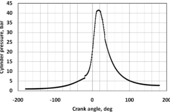
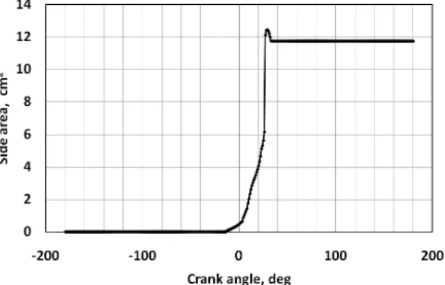
Computer simulation has been developed to predict the performance of a spark ignition engine. The effects of various cylinder pressure, heat release, flame temperature, unburned gas temperature, flame properties, laminar burning velocity, turbulence burning velocity, etc. were simulated. The simulation and analysis show several meaningful results. The objective of the present study is to develop a combustion model for a spark ignition engine running with isooctane as a fuel and predicting its behavior.

Key words : Spark ignition engine, thermodynamic engine model, compression, combustion, expansion, one-dimensional model, two-zone combustion model

http://dx.doi.org/10.5855/ENERGY.2015.24.3.055

(2)

ning with isooctane as a fuel and predicting its behavior.

2. Thermodynamic Engine Model

Thermodynamic model of the gasoline fueled en- gine is considered the closed system that both inlet and exhaust valves remain closed. The important events such as compression, combustion, and expan- sion take place during this period. The engine is re- duced to a thermodynamic system, which consist of a homogeneous mixture of air, gasoline, and residual gas from the previous cycle. The boundaries of the system are the cylinder walls, cylinder head, and top of the piston head. Work is added to or taken from the system through the motion of the piston and heat is transferred to or from the system through the boundary surfaces [2].

Thermodynamic models can be classified into two groups; one-zone model and multi-zone model. In one-zone model, the cylinder charge is assumed to be uniform in both composition and temperature and the first law of thermodynamics is used to calculate the mixture energy. One-zone model represents the unburned mixture ahead of the flame and one the burned mixture behind the flame.

In two-zone model, the cylinder mixture is div- ided into burned and unburned zones, which are separate from each other by a surface of dis conti- nuity. The composition and temperature of the burned and unburned gases are different and the pressure is uniform through out the combustion chamber. Two-zone model is used to calculate the mass fraction burned profile from measured cylinder pressure data [3].

In this model, the following assumptions have been used.

- The burnt and unburned gases are assumed to be ideal and non-reacting. The heat transfer from the burned to unburned gases is assumed to be negligible. The pressure is constant for both the zones. There is assumed to be no dissociation in the unburned gases prior to combustion.

- Cylinder volume at any instant consists of burned and unburned zones separated by a thin infinitesimal flame front. Flame propagates in a spherical pattern.

- The rate of heat transfer from gas to the wall depends on instantaneous heat transfer co- efficient, concerned surface area, and difference in temperature between the gas and wall.

- The charge in the cylinder at any instant con- sists of fuel-air mixture and residual gases. Ideal gas equation is assumed to be valid for the mix- ture of gases.

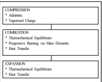
Figure 1 shows the general structure of the ther- modynamics model.

Thermodynamic engine model is based on the first law of thermodynamics expressed as [4, 5]:

         

 



 

 







The governing equation for the burned and un- burned gas zones can be written as:

  

 

 

   



  



  

 

where the subscripts u and b denote the unburned COMPRESSION

* Adiabatic * Vaporized Charge

COMBUSTION

* Thermochemical Equilibrium

* Progressive Burning via Mass Elements * Heat Transfer

EXPANSION

* Thermochemical Equilibrium * Heat Transfer

Figure 1. Block diagram of thermodynamic model.

(3)

and burned gases, respectively.

The following system of equations:





 

   

 

  

 

 

 







 

   

 

  

 

 

 



  

 

 

  

 

 

The unburned temperature is determined using the isentropic relationship in following equations:



 

 



In the model, heat from combustion is supplied using a Wiebe function:

    Exp       



 

 

   

 

  

  

Exp   

  

 

With a=5 and m=2, 

is the spark time at the be- ginning of combustion in crank angle and  is the total combustion duration (x

b

= 0 to x

b

= 1).

The heat release rate is given by:

 

 

    

   

 

    

 





 

 

 



 

  



 





 

The specific heat ratio is estimated using NASA interpolations of specific heats at constant pressure.

The interpolating polynomials are given on a form [5, 6]:

 

  

 

 

 

 

 

 

  

 

 

 

The specific heat ratio can then be calculated

   

 

Pressure is calculated from the equation:

 

 

 

 

    

 

The total volume of the gases inside the cylinder at a particular crank angle is given by the ex- pression:

 

 

  

 

  sin   

  

3. Results

Figure 2 shows the cylinder pressure in a spark ignition engine as a function of crank angle. The pressure from this thermodynamics model reveals that it is shown the peak pressure 42 bar at around 18 degree after TDC (top dead center).

The calculation condition for compression, combus- tion, and expansion predictions is shown in Table 1.

The model assumes that crank angle is simulated.

This implies that the diagnostic version of the heat release equation can be used to calculate the quanti- ties of heat released at each crank angle [7, 8].

Figure 2. Variation of cylinder pressure with crank

angle.

(4)

Figure 3. shows the simulated heat release curve.

Under simulated condition, the heat release is about 16 cal/cycle.

During the compression, combustion and ex- pansion, the combustion period is assumed that the spark ignited flame front divides the in-cylinder gas mixture into two zones : the burned and unburned zones. To simplify the two-zone combustion model, the shape of the burned zone is assumed to be a cir- cle centered at the cylinder [9]. For the spark igni- tion combustion the temperature of the unburned zone is quite different from that of the burned zone as seen in Figure 4 and Figure 5.

At any given flame radius, the geometry of the combustion chamber and the spark plug location govern the flame front surface area, the area of the approximately spherical surface corresponding to the leading edge of the flame contained by the piston, cylinder head, and cylinder wall. The larger this sur-

face area, the greater the mass of fresh charge that can cross this surface and enter the flame zone [3].

The flame is assumed to propagate spherically from the one end of the cylinder. As the flame pro- ceeds from one end to other the traveled portion of cylinder volume was assumed completely burned, while the other as unburned [2].

Figure 6, 7, 8, and 9 show the variation of vol- ume area, flame radius, flame area, and side area with crank angle, respectively.

An important inherent property of a combustible fuel, air, burned gas mixture is its laminar burning velocity. This burning velocity is defined as the ve- locity, relative to and normal to the flame front, with which unburned gas moves into the front and is transformed to products under laminar flow con- ditions [3]. Figure 10, and 11 show the variation of laminar burning velocity, and turbulence burning ve-

Figure 5. Variation of unburned gas temperature with crank angle.

Figure 4. Variation of flame temperature with crank angle.

Figure 3. Variation of heat release with crank angle.

Items Specification

Bore x Stroke 90 x 70 mm

Displacement 445 cc

Compression ratio 4.5 Connecting rod 133 mm

Engine speed 1,600 rpm Spark advance 23° (BTDC)

Air fuel ratio 13:1

Mixture Isooctane and air

Table 1. Calculation condition for simulation.

(5)

locity with crank angle, respectively.

4. Conclusions

The simulation has be come a powerful tool as it saves time and also economical when compared to experimental study. The following conclusions can

be made from above research;

The pressure from this thermodynamics model re- veals that it is shown the peak pressure 42 bar at around 18 degree after top dead center.

During the compression, combustion and expan- sion, the combustion period is assumed that the Figure 7. Variation of flame radius with crank angle.

Figure 8. Variation of flame area with crank angle.

Figure 6. Variation of volume area with crank angle.

Figure 10. Variation of laminar burning velocity with crank angle.

Figure 11. Variation of turbulence burning velocity with crank angle.

Figure 9. Variation of side area with crank angle.

(6)

spark ignited flame front divides the in-cylinder gas mixture into two zones : the burned and unburned zones.

The effects of various cylinder pressure, heat re- lease, flame temperature, unburned gas temperature, flame properties, laminar burning velocity, turbu- lence burning velocity, turbulence flame velocity, etc. were simulated. The simulation and analysis show several meaningful results.

Nomenclature A flame area B cylinder bore D diameter of piston h heat transfer coefficient k specific heat ratio m mass of mixture P gas pressure Q heat of the gases R universal gas constant r crank radius

S stroke

SL laminar flame speed T temperature

θ crank angle ϒ specific heat ratio ρ density of mixture

subscripts

b burned

u unburned

References

1. Heywood, J. B., Combustion Modelling in Recip- rocating Engines (Engine Combustion Modeling- An Overview), Plenum Press, 1980, 1-38 2. Sakthinathan, G. P. and Jeyachandran, K., Theo-

retical and experimental validation of hydrogen fueled spark ignition engine, Thermal Science, Vol.14, No.4, pp.989-1000, 2010.

3. Heywood, J. B., Internal Combustion Engine Fun- damentals, Mc-Graw Hill, 1987.

4. Ribeiro, B., Martins, J. and Nunes, A., Genera- tion of Entropy in Spark Ignition Engines, Int. J.

of Thermodynamics, Vol. 10, No.2, pp.53-60, 2007.

5. Goodwin, A. R.; Sengers, J. V.; Peters, C. J., Ap- plied Thermodynamics of Fluids, RSC Publishing, 2010.

6. Cengel Y. A.; and Boles, M. A., An Engineering Approach Thermodynamics, McGrow Hill, Second Edition, 1994.

7. Thompson, I. G., Spence, S. W., Thornhill, D., McCartan, C. D. and Talbot-Weiss, J. M., The technical merits of turbogenerating shown through the design, validation and implementation of a one-dimensional engine model, International of Engine Research, Vol.15, No.1, pp.66-77, 2014.

8. Muric, K, Stenlaas, O. and Tunestal, P., Zero-di- mensional modeling of NOx formation with least squares interpolation, International of Engine Re- search, Vol.15, No.8, pp.944-953, 2014.

9. Yang, X. and Zhu, G. G., A control-oriented hy- brid combustion model of a homogeneous charge compression ignition capable spark ignition engine.

Proc IMech Part D: Journal of Automotive En-

gineering, Vol.226, No.10, pp.1380-1395, 2012.

수치

Figure  1  shows  the  general  structure  of  the  ther- ther-modynamics  model.
Figure  2.  Variation  of  cylinder  pressure  with  crank  angle.
Figure  4.  Variation  of  flame  temperature  with  crank  angle.
Figure  8.  Variation  of  flame  area  with  crank  angle.

참조

관련 문서

- distributes indexes across multiple computers and/or multiple sites - essential for fast query processing with large numbers of documents - many variations:

Others: waste heat in distillation tower, waste heat recovery, natural gas pressure turbine, by-product gas Source: The monthly report on major electric power statistics,

The purpose of this study is to evaluate the effects of heat treatment on the load-deflection properties and transitional temperature range(TTR) of

A jet pump is a fluid carrying device which spouts fluid of high pressure from a driving engine pipe and absorbs fluid of high pressure whose pressure

Using selected engine performance simulation results as input to the intake faces of the nozzles and ejector CFD simulation to determine pressure loss, temperature levels and

To visualize the vari- ation in various transport characteristics (the non-dimen- sional axial velocity and temperature distributions, pressure gradient, rate of heat

▪ Local temperature of PMSM can be calculated through thermal resistance model and heat generation model, presenting the cooling performance thermal

– Reversible cyclic process with Ideal gas – Maximum efficiency of a