1
1) 전남대학교 에너지자원공학과 2) (주)NSB 나우이엔씨
3) 한국광물자원공사
* 교신저자 [email protected] 접수일 : 2018년 9월 10일 심사 완료일 : 2018년 9월 27일 게재 승인일 : 2018년 12월 5일
Abstract This numerical study was intended to evaluate the applicability of the half charge blasting to mining and tunnelling. The half charge blasting is a method that two separate rounds are sequentially blasted for the rock burdens in which long blast holes have already been drilled at one operation. The aim of the method is to decrease the construction cost and period in mining and tunnelling projects as well as to increase the blasting efficiency. Several numerical analyses were conducted by using the Euler-Lagrange solver on ANSYS AUTODYN to identify the effects of the suggested method on the blasting results in underground excavations. The overall performance of the suggested method was also compared to an ordinary blasting method. The analysis model was comprised of the Eulerian parts (explosive, air, and stemming materials) and the Lagrangian parts (rock material). As a result, it was found that, owing to the air decks formed in the bottom parts of the long blast holes, the first round of the suggested method presented a higher shock pressure and particle velocities in the vicinity of the blast holes compared to the ordinary blasting method.
Key words Half charge blasting, AUTODYN, Euler-Lagrange solver, Air deck, Blast pressure, Mine blast, Tunnel blast, Particle velocity
초 록 본 수치해석 연구는 하프장전 발파법의 채광발파 및 터널발파에의 적용성을 평가하기 위해 수행되었다.
하프장전 발파란 한 차례의 천공공정 중에 설계된 공깊이보다 2배로 깊은 발파공을 미리 천공한 다음, 연속적인 두 차례의 발파공정을 통해 굴착하는 방법을 말한다. 이 방법의 목표는 발파효율의 향상뿐만 아니라 광산발파나
제36권 제4호, 2018년 12월, pp. 1~8 Journal of Korean Society of Explosives & Blasting EngineeringNumerical Study on the Effects of Air Decking in Half Charge Blasting Using AUTODYN
Khaqan Baluch 1) , Jung-Kyu Kim 1) , Seung-Jun Kim 1) , Jin Guochen 1) , Seung-Won Jung, 1) Hyung-Sik Yang 1)* , Nam-Soo Kim 2) , Jong-Gwan Kim 3)
AUTODYN을 이용한 하프장전 발파공법의 에어데크 효과에 대한 수치해석적 연구
Khaqan Baluch, 김정규, 김승준, Jin Guochen,
정승원, 양형식* ,김남수,
김종관1)터널굴착 프로젝트에서 공사비용과 공기를 단축시키는 데 있다. 본 연구에서는 ANSYS AUTODYN 프로그램 상 의 Euler-Lagrange 해석기를 사용하여 몇 차례의 해석을 실시함으로써 제안된 방법이 지하굴착에서의 발파결과에 어떠한 영향을 미치는지를 확인하였다. 해석모델은 오일러 모델(폭약, 공기 및 전색 재료)과 라그랑쥬 모델(암석 재료)로 구성되어 있다. 해석 결과, 제안된 발파방법의 경우에는 긴 발파공의 바닥부에 형성되는 에어데크로 인 하여 통상의 발파방법에 비해 발파공 부근에서 더 높은 충격압력과 입자속도를 발휘하는 것으로 나타났다.
핵심어 하프장전 발파, AUTODYN, Euler-Lagrange 해석기, 에어데크, 발파압력, 채광발파, 터널발파, 입자속도
1. Introduction
Half charge blasting is a new method for a tunnel or mine blasting. In the half charge blasting method, the drilling length becomes twice that of ordinary blasting methods. For example, if an advance per round is 1.6 m, then the blast holes of depth 3.2 m are drilled in one operation. Then, in the first blast round, the explosive is charged into only half length (1.6 m) of each blast hole (3.2 m) and the other half (1.6 m) of the hole is kept empty. In the second round, the explosive is charged into the remaining half (1.6 m) of each hole and then blasted.
There are some differences in the steps of excavation cycle between the half charge blasting
method and an ordinary blasting method, as shown in Fig. 1. If the half charge blasting method is used, the time required for the drilling operation will be dramatically reduced. This is mainly because the total time needed for the drilling machine to repeatedly move between the face and the shelter will be saved greatly. Furthermore, the blasting efficiency of the first round can increase because the empty part of each blast hole acts as an air deck. Jhanwar (2011) showed that when there is an air deck at the bottom of a blast hole, the shock pressure and the kinetic energy can increase 2-7 and 50-100 times, respectively.
Therefore, if the half charge blasting method is used, it is expected that better blasting results can be achieved with less amount of explosives.
(a) excavation cycle of ordinary blasting method
(b) excavation cycle of half charge blasting method
Fig. 1. Excavation cycles of the ordinary and half charge blasting methods.
2. Numerical models and mechanical properties of materials
AUTODYN software was used to compare the short-time blasting effects of the half charge blasting method and an ordinary blasting method. In the simulations, the blasting effects were estimated by means of the pressure time histories and particle velocities generated in the rock mass.
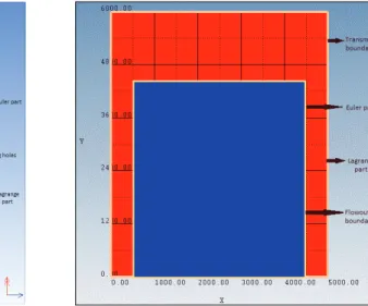
The whole analysis model was comprised of two parts (Fig. 2): Lagrangian and Eulerian parts. In the Lagrange formulation, the mesh is moved and distorted (cracks) according to the material movement.
This is the reason why the Lagrangian formulation is used mainly for modelling solid media. In the present model, the rock structure was modelled as a Lagrangian part. The dimensions of the Lagrange part were 5 × and 6 × mm in the directions of x and y axes, respectively. There were 60,000 elements in the Lagrange part.
In contrast, in the Euler formulation, the mesh remains fixed in space while materials flow through it. This is the reason that the Eulerian formulation is really good for modelling various fluid materials (Persson, 1994). In the present model, the air, explosive, and stemming materials were modelled as
the Eulerian parts. The dimensions of the whole Eulerian part was 4 × and 6 × mm in the directions of x and y axes, respectively. There were 40,000 elements in the Eulerian part.
The diameters of the blasting holes and the explosives were 50 and 32 mm, respectively (Hanwha Corporation, 2014). A blasting pattern with a V-cut has adopted for the simulation as shown in Fig. 3.
The explosive and stemming materials were emulsion and sand, respectively.
The boundaries of the rock structure were defined to be viscous boundaries, which represents the infinite boundary through which the blast waves can freely pass away. The boundaries of the air part were defined to be flow-out boundaries, through which the air pressure can freely pass away.
The ALE (Arbitrary Lagrangian-Eulerian) meshing algorithm in AUTODYN allows the arbitrary movement of numerical meshes between Eulerian (fixed) and Lagrangian (moving) specifications, and thus can provide an automatic interaction and mesh rezoning, usually called the FSI (fluid-structure interaction). The properties of rock (Lagrangian) part are given in Table 1, in which “alpha” and “beta”
are compression-state exponential interpolation parameters, “a” is Tillotson parameter, “A” is bulk
Fig. 2. Dimensions and boundary conditions of the analysis model.
modulus (kbar), “b” is Tillotson parameter, and “B”
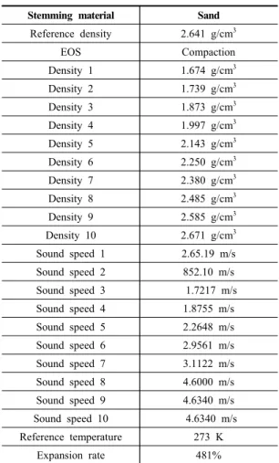
is Tillotson parameter (kbar), “es” is the sublimation energy, “eo” is energy of incipient, and “esd” is the energy of complete vaporization. The properties of explosive (emulsion) are given in Table 2. The properties of sand (stemming material) are given in Table 3, in which there are 10 different densities that are automatically set by the software. As the pressure becomes higher, the density as well as the sound speed become higher accordingly, and vice versa. All the mechanical properties of materials have been taken from known sources and AUTODYN libraries.
Rock Granite
Reference density 2.75 g/cm 3
EOS Tillotson
Parameter A 18,000,000 kPa Parameter B 18,000,000 kPa
Parameter a 0.5
Parameter b 1.3
Parameter alpha 5
Parameter beta 5
Parameter eo 0.016 J/kg Parameter es 0.0035 J/kg Parameter esd 0.018 J/kg Reference temperature 273 K
Expansion rate 481 %
Table 1. Mechanical properties of rock (Lagrange) (Belal and Hassan, 2013)
Stemming material Sand
Reference density 2.641 g/cm 3
EOS Compaction
Density 1 1.674 g/cm 3 Density 2 1.739 g/cm 3 Density 3 1.873 g/cm 3 Density 4 1.997 g/cm 3 Density 5 2.143 g/cm 3 Density 6 2.250 g/cm 3 Density 7 2.380 g/cm 3 Density 8 2.485 g/cm 3 Density 9 2.585 g/cm 3 Density 10 2.671 g/cm 3 Sound speed 1 2.65.19 m/s Sound speed 2 852.10 m/s Sound speed 3 1.7217 m/s Sound speed 4 1.8755 m/s Sound speed 5 2.2648 m/s Sound speed 6 2.9561 m/s Sound speed 7 3.1122 m/s Sound speed 8 4.6000 m/s Sound speed 9 4.6340 m/s Sound speed 10 4.6340 m/s Reference temperature 273 K
Expansion rate 481%
Table 2. Mechanical properties of sand (stemming)
Explosive Emulsion
Density 1.0 g/cm 3
EOS JWL
Detonation velocity 5700 m/s Table 3. Mechanical properties of explosive
(a) Half blast model (b) Remaining part (c) Ordinary blast model
Fig. 3. AUTODYN analysis models.
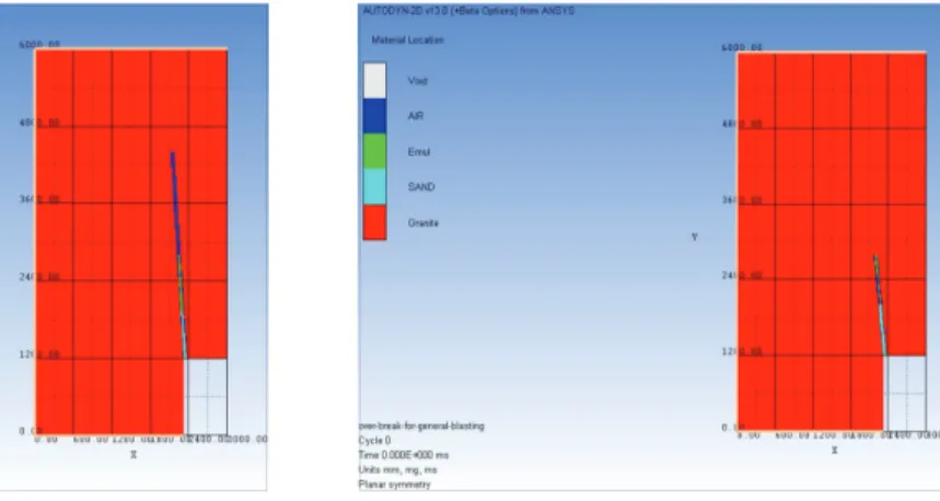
In Fig. 3, the blue color represents air, the yellow color the emulsion explosives, and the red color the Lagrangian part (rock). In addition, two gauges were installed at the same locations in all three models to calculate blast pressures. For the contour holes, there were two models for the half charge and ordinary blasts. Fig. 4 shows two contour blast models. Both models had the same dimensions of (3 × 10 3 mm) × (6 × 10 3 mm) with respect to x and y axes. The blast holes had the diameter of 50 mm with the bottom charge of diameter 32 mm and the column charge of diameter 17 mm.
2.1 Numerical simulation results