Research paper
한국동력기계공학회지 제17권 제6호, 2013년 12월 47
Experimental Investigations on the Temperature Characteristics of Oscillating Heat Pipe with Various Filling Ratio
Hyo-Min Jeong * , Han-Shik Chung * , Kwang-Sung Lee ** , Md.Riyad Tanshen ** †, Tae-Jin Lee *** , Sin-IL Lee ****
(received 19 January 2011, revised 4 June 2013, accepted 18 Junel 2013)
Abstract: The article focuses on the Temperature characteristics inside single loop oscillating heat pipe (OHPs). In this paper, heat pipe is experimentally studied thereby providing vital information on the parameter dependency of their thermal performance. The impact depiction has been done for the variation of tube model of the device. OHPs are made of copper capillary tubes of outer diameter 6.25 mm, inner diameter 4 mm heated by constant temperature water bath cooled by ambient temperature. Using four types of OHPs of copper capillary tubes length of 1500mm and HP length 650mm inside tubes working fluid is R-22 Pressure 8 bar and mass 34g,32g,28g,16g. The results indicate a strong influence of filling ratio on the performance
Key Words:Oscillating Heat pipe, Heat transfer, Capillary tube, Filling ratio.
**†Md.Riyad Tanshen (corresponding author) : Department of Energy and Mechanical Engineering, Gyeongsang National University.
E-mail : [email protected], Tel :+8210-24603444
*Hyo-Min Jeong, Han-Shik Chung : Department of Energy and Mechanical Engineering, Institute of Marine Industry, Gyeongsang National University.
***Tae-Jin Lee : Dept. of Energy and Mechanical Engineering, Gyeongsang National University.
****Sin-IL Lee : Dept. of Energy and Mechanical Engineering, Gyeongsang National University.
― Nomenclature ―
Bo : Bond Number Eö : Etövös number D : tube diameter
g : acceleration of gravity [m/s2]
t : Time V : Volume FR : Filled ratio
Greek Symbols
ρ : Density [kg/m3] 𝜎 : Surface Tension [N/m]
Subscripts
cri Critical value
i inner
liq Liquid vap Vapor
1. Introduction
Lately many experiments have been studied in the field of oscillating heat pipe because of its specific features. Extended investigations of OHPs have been investigated since the first OHPs developed by Akachi in 1990 The mechanism occurs in OHP is the
utilization of pressure change in volume expansion and contraction during phase change to excite oscillating motion of liquid plugs and vapor bubbles between evaporator and condenser. Comparing OHP with other conventional heat transfer pipes, the unique feature of OHPs is that there is no wick structure to return the condensate to the evaporator and therefore there is no counter current flow between the liquid and the vapor flows because both operates in the same direction (1) The thermally-driven oscillating flow inside capillary tube effectively produces some free surfaces that significantly enhance evaporating and condensing heat transfer. (2) The oscillating motion in the capillary tube significantly enhances the forced convection in addition to the phase-change heat transfer. These all significant characters of OHP make itself very special heat transfer device in modern application. Past works over OHPs can be concluded within several features like heat transfer characteristics and capability with different filling ratio, flow visualization inside OHP, effects of length ratio and diameter on performance of OHP, nanofluid and other applicable fluids has been used as working fluid for developing OHP performance1~2)
Khandekar et al, Rittidech et al and Tong et al.
[5] had discussed the effects of many parameters on thermal performance, such as internal diameter, number of turns, working fluid and inclination angle of the device3~5). Wang and Nishio investigated the effect of length ratio of heating section to cooling section on the ultimate heat transport capability of OHP6. The effect of gravity on slug flow and effect of number of turns on spatial dynamic pressure influences the OHP performance. Besides the input heat is also a strong parameter that affects dynamic instability especially in density wave oscillation7~8)
Gi et al, conducted flow visualization for closed-loop PHP made from Teflon tube of 2 mm internal diameter and partially filled with R142b.
The PHP consisted of 10 meandering turns and it is 400 mm from the evaporator to condenser. The evaporator was heated by a hot bath and the condenser was cooled by a cold bath. It was concluded that the best thermal performance for the PHP is achieved when the FR is from 0.5 to 0.69.
In 1998 Chandratilleke et al. [10] developed the cryogenic loop heat pipes. The development of cry cooler cooled superconducting magnets applications, where heat transport distance is large, and the heat conduction by a copper block will be constrained by its cross section transport capacity10. Q. Mo et al.
shows that the heat transport capacity of loop heat pipe with liquid nitrogen as working fluid is very low- only 26 W hen it operates in horizontal direction and its lowest thermal resistance reaches 1.3 K/W, which is too high for most of cryogenic heat transport system11~12. Most recently, it has been found that when nanoparticles or micro particles were added into the base fluid in an OHP, the heat transport capability can be increased. The thermally-excited oscillating motion in the OHP can make the particles suspend in the base fluid13.
Maezawa et al, reported that the appearance and movement of bubbles are affected by surface tension and buoyancy in the channel14. Relation of surface tension and buoyancy could be explained by the following dimensionless formula:
o g E
Di
Bo lic vap ⎥ = &&
⎦
⎢ ⎤
⎣
⎡ −
=
5 .
) 0
( σ
ρ ρ
when E &&o≈4,the bubble will get seized on both side of the wall but not moving statically, and the liquid forms liquid slug flow, calculate instead of getting the critical pipe diameter D cri of OHP. The formula is
D g D
vap lic cri
i 2* ( )
ρ ρ
σ
≤ −
<
한국동력기계공학회지 제17권 제6호, 2013년 12월 49
2. Experimental setup and method
Fig. 1 shows the schematic diagram of experimental setup having condensing and evaporating section.
The OHPs is made of high quality copper capillary tube with the total lengths of 1500 mm and I-type heat pipe lengths 650 mm the inner diameter 4 mm. The temperatures of the evaporator section were maintained at below 100°±2°C. A data logger (Yokogawa DA100 with ±0.1°C accuracy, was used with T-type thermocouples (its measurement range from (-200°C to 350 °C). Four capillary tubes with single height of cooling section of 80 mm are used.
i.e, Single capillary tube, double capillary tube, circle type and I-type tubes. To measure the temperature, thermocouples were attached in the top and bottom section of OHPs in certain distances. Oscillating Heat Pipe (OHP) having three parts: evaporator section, cooling section and adiabatic section. All height of evaporator section is 75 mm. All the vertical capillary tubes have two ports for vacuum and charging the OHPs. It was vacuumed then filled with R-22. The filling ratios is defined as the wet liquid volume divided by the total inside volume of the OHPs and HP. Evaporator section heated by hot water and condenser section cold by air. Data taking duration was about 5 mints.
Fig. 1 Schematic diagram of experimental setup
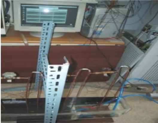
Fig. 2 Experimental set up photo
Fig. 3 Real experiment OHPs and HP photo
3. OHP working principle and the influencing para meters
If the diameter of a capillary tube is so small such that the vapor plug and liquid slug distributed inside the capillary tube can be formed for vacuum capillary tube when liquid is charged. The liquid film between the vapor plug and the inner wall will evaporate in the evaporator, in result of the pressure of the vapor increased, pushing the vapor plug and liquid slug to the condenser region, and the vapor which reaches the condenser section will condense and shrink. The heat received in the evaporator is dissipated to the condenser region. The heat received in the evaporator is the energy source that provides the driving force to cause fluid flow. Fluid motion begins when the liquid slug, which is adjacent to the plug in the evaporator region, is pushed due to the
high pressure of the plug, and the motion is enhanced when the vapor shrink in the condenser region. From the working principle of the OHP, the oscillation in the OHP relies on three driving forces:
gravity force, surface tension, and oscillating force, which comes from the pressure fluctuating between the evaporator and condenser. These forces are influenced by many factors. The gravity force is influenced by the inclination angle of the device, the physical features such as channel size and shape can have a significant effect on the surface tension, and the heat flux has great effect on the oscillating force. For the two-phase flow pattern existing in the OHP, the liquid along the tube blocks the motion of the vapor. So, it's also a parameter which has effect on the thermal operation of the OHP, and this is embodied by the filling ratio. It has been indicated by earlier studies that there are a large number of para-meters influencing the operation of the OHP.
These can be summarized as: (a) geometrical parameters, i.e., diameter of tube, cross section shape of tube, length of evaporator/condenser section, overall length of the device, number of turns, (b) operational parameters, i.e., global orientation, and (c) physical parameters i.e., thermo-physical properties of working fluid and its filling ratio. It is noted that most of the works were focused on the experimental study. The objective of this work is to analyze the influence of primary parameters: filling ratio, temperature characteristics and the capillary tube of the device.
3. Result and Discussion
The overall Temperature characteristic has been used to estimate the performance of the OHP, Convective and conductive heat transfer has been considered in this study.
3.1 The effects of heat input
The heat input in the evaporator is the energy source of the fluid. When heat is added to the evaporator, the pressure and temperature of the vapor in the evaporator are increased.
3.2 The effects of filled ratio
Fill ratio also has a significant influence on the characteristic of heat transfer. The effects of fill ratio are introduced in four capillary tubes such as circle type tube, single capillary tube, double capillary tube and I type tube.
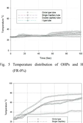
Fig. 5 Temperature distribution of OHPs and HP (FR-0%)
Fig. 6 Temperature distribution of OHPs and HP (FR-25%)
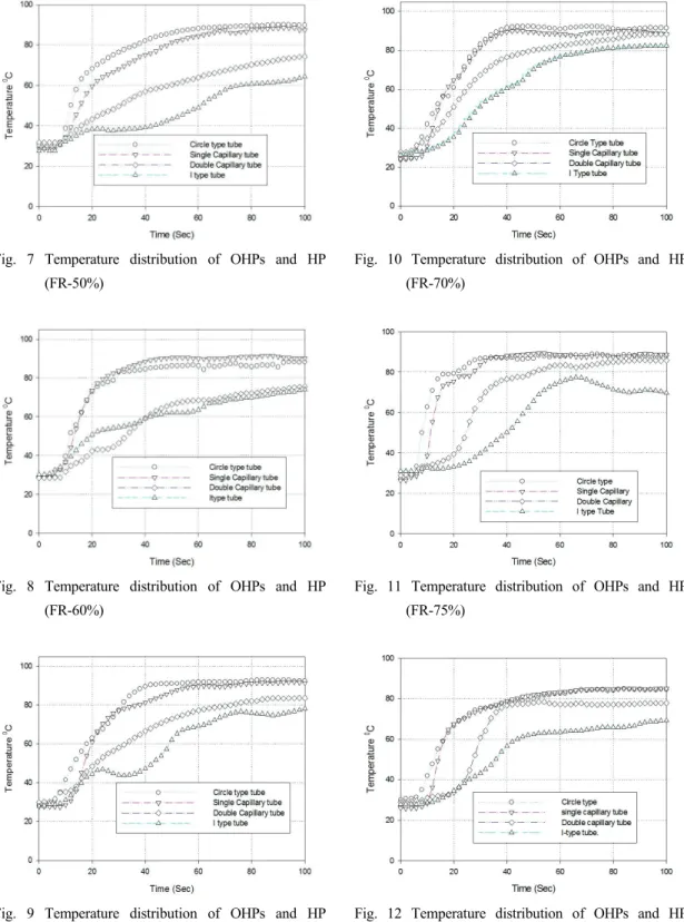
한국동력기계공학회지 제17권 제6호, 2013년 12월 51 Fig. 7 Temperature distribution of OHPs and HP
(FR-50%)
Fig. 8 Temperature distribution of OHPs and HP (FR-60%)
Fig. 9 Temperature distribution of OHPs and HP (FR-65%)
Fig. 10 Temperature distribution of OHPs and HP (FR-70%)
Fig. 11 Temperature distribution of OHPs and HP (FR-75%)
Fig. 12 Temperature distribution of OHPs and HP (FR-80%)
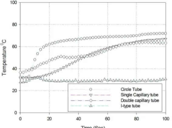
Fig. 13 Temperature distribution of OHPs and HP (FR-100%)
Fig. 14 Temperature distribution of OHPs and HP (FR=0-100%)
The heat transfer rates at different filling ratio of working fluid were shown in Fig. 10 circle type tube the heat transfer rate increases with the fill ratio and it reaches the maximum heat transfer rate at the filling ratio 70% that shows temperature of 88°C at time 40 Sec and Fig. 11 shows also high performance maximum temperature 85°C at time 40 sec. I type tube maximum temperature distribution 75°C at time 60 sec. It has been found that if filling ratio is increased more, heat transfer performance decreases as when the fill ratio is over 80%. So OHP performs better at 70% fill ratio in this case.
When the filling ratio is high enough, there crates
few bubbles in tubes, and the effective oscillation can't be achieved. When OHP is fully filled with the working fluid (FR=100%), the oscillation of the plug and slug can't formed. In this case the heat transfer of the OHPs and HP is only by conduction, In fact, there exists an optimum filling ratio. More the bubbles (lower fill ratio), more is the degree of freedom but simultaneously there is less liquid mass for sensible heat transfer. Less bubble (higher fill ratio) Fig. 12 causes less perturbations and the bubble pumping action is reduced there by lowering the performance. Under the optimum filling ratio and the working fluid in the tubes is enough for the flow motion, so there also have enough vapor to supply the driving force of the fluid motion. Fig. 13 shows circle type tube temperature maximum 65°C also I type tube heat pipe temperature 35°C and single and double capillary tube almost same temperature 61°C. Temperature distribution of oscillating heat pipe with respect to filling ratio is shows in Fig. 14. 0% filling ratio shown lowest temperature and higher temperature shown 70%
filling ratio. The temperature distribution using various filling ratio is among Three different types of OPHs 70% filling ratio shows circle type tube higher heat transfers near about single capillary tube and double capillary tube lowest temperature distribution is I-type tube heat pipe.
5. Conclusions
1. The optimum filling ratio is about 70% creates more slugs into OHP that drives more heat from evaporative section to condensing section. So the temperature distribution high. When the fill ratio is 70% the operation of the OHP is better than other modes.
2. The circle type tube produces best performance at the ratio of 70%.
3. Circle type tube oscillating heat pipe batter
한국동력기계공학회지 제17권 제6호, 2013년 12월 53 than I type tube heat pipe.
Acknowledgement
This research was supported by Basic Science Program through the National Research Foundation of Korea (NRF) funded by the Ministry of Education, Science and Technology(KRF-2011- 0009022) and the Future Leading Project through the Small and Medium Business Administration (No.S2044441)
References
1. H. Akachi, 1990, Patent no. 4921041 Structure of a Heat Pipe.
2. Y. W. Zhang, A. Faghri, 2008, “Advances and unsolved issues in pulsating heat pipes”, Heat Transfer Eng. 29 (1), pp. 20-44.
3. S. Khandekar et al, 2003, “Closed Loop Pulsating Heat Pipes: Part A: Parametric Experimental Investigations”, Applied Thermal Engineering, pp. 2009-2020. 333-2340.
4. S. Rittidech et al., 2003, “Correlation to Predict Heat Transfer Characteristics of a Closed-End Oscillating Heat Pipe at Normal Operating Condition”, Applied Thermal Engineering 23, pp.
497-510.
5. B. Tong, T. Wong, K. Ooi, 2001, “Closed-loop pulsating heat pipe”, Applied Thermal Engineerinsg 21, pp. 1845-1862.
6. S. F Wang, S. Nishio, 2007, “Effect of length ratio of heating section to cooling section on properties of oscillating heat pipe”, Huanan Ligong Daxue Xuebao/Journal of South China University of Technology (Natural Science) 35(11), pp. 59-62.
7. K. Gi, F. Sato, et al, 1999, “Flow Visualization Experiment on oscillating Capillary heat Pipe”.
11th International heat pipe Conference, Japan,
pp. 149-153.
8. J. Boure, A. Bergles, L. Tong, 1973, “Review of two-phase flow instability”, Nucl. Eng. Design 25, pp. 165-192.
9. P. Saha, M. Ishii, N. Zuber, 1976, “An experimental investigation of thermally induced flow oscillations in two-phase system”, ASME J.
Heat Transfer 98, pp. 616-622.
10. R. Chandratilleke, H. Hatakeyama, H. Nakagome, 1998, “Development of cryuogenic loop heat pipes”, Cryogenics 38 (3), 263-269.
11. Q. Mo, J. T. Liang, 2006, “A novel desigh and experimental study of cryogenic loop heat pipe with high heat transfer capability”, Int. J. Heat Mass Transfer 49, pp. 770-776.
12. Q. Mo, J. T. Liang, J. H. Cai, 2007,
“Investigation of the effects of three key parameters on heat transfer capability of CLHP with insufficient working fluid inventory”, Cryogenics 47, pp. 262-266.
13. H. B. Ma, C. Wilson, Q. Yu, K. Park, U.S.
Choi, M. Tirumala, 2006, “An experimental investigation of heat transport capability in a nanoflid oscillating heat pipe”, J. Heat Transfer 128, pp. 1213-1216.
14. S. Maezawa, K. Y. Gi, A. Minamisawa, H.
Akachi, 1996, “Thermal performance of capillary tube thermosyphon”, in Proceeding of the 9th International Heat Pipe Conference. Albuquerque, USA, Vol. 2, pp. 791-795.