전자기 펄스 용접의 원리 및 적용
강봉용․심지연․강문진․김인주
Principle and Application of Magnetic Pulse Welding
Bong-Yong Kang, Ji-Yeon Shim, Moon-Jin Kang and In-Ju Kim1. 서 론
최근 금속가공산업은 자동차, 조선 기계, 전자 등의 부품소재 제조에 있어 핵심적인 산업으로 자리하고 있 다. 특히 가장 많은 비중을 차지하고 있는 용접산업은 저임금을 바탕으로 한 중국기술의 추격과 선진국의 고 품질화에 직면하고 있으며 이러한 문제를 해결하기 위 하여 친환경 공정기술의 개발과 신기술을 통한 제품의 부가가치 제고가 요구된다.
MPW는 자기장에 의한 전자기력을 사용하므로 물리 적인 접촉 없이 금속을 가공하는 방법으로서, 용접 (brazing과 soldering 포함), 금형 및 소성가공공정에 서 환경오염 발생원인 용접재료, 가스, 용가재, 플럭스, 윤활유 및 세척유 등이 필요 없이도 고품질의 제품을 생산할 수 있는 친환경적인 공정기술이다. 그 외에도 도금된 상태에서 작업이 가능하여 기존의 공정에서 결 함이 발생되었을 때 재도금을 실시하는 후공정이 생략 되어 도금공정에서 배출되는 오염물질도 줄일 수 있고, 작업이 수 μs 하에서 이루어지기 때문에 전력소모가 매우 적으며 작업시간을 절약할 수 있는 장점을 갖고 있다1). MPW 기술은 초기에 구 소련(Soviet Union)에서 제한적으로 군사 분야에 적용을 위하여 개발되었다. 그 이후에 자동차, 가전 등의 분야에서 본 기술에 대한 산 업적 응용에 관심을 갖기 시작하였으며. 1980년 M.
Kojima2)등에 의해 본격적으로 이종금속의 접합에 관 한 연구가 시작되었다. 이후 H. Hokari3)등에 의해 공 정변수에 따른 접합부 특성이 보고되었다. 최근 EWI (Edsion Welding Institute), TWI(The Welding Institute), HIT(Harbin Institute of Technology) 및 OSU(Ohio State University)를 중심으로 체계적 인 이론 확립과 이종금속 접합 실험과 수치해석을 통한 MPW공정 최적화에 연구가 진행되고 있다.
최근에는 Pulsar사, Dana사 및 Magneform사 등 이 장비 및 시스템을 개발하여 보급하고 있으며 GM,
Ford, Arvin Hutchinson과 같은 자동차회사와 Boeing, Lockheed Martin, Pratt and Whitney와 같은 항 공회사, AMP, Thomas, Betts, Electrolux, Whirlpool 등의 전기/전자회사의 실제 생산현장에서 MPW기술을 현장에 적용하여 높은 생산성과를 통한 경제적인 개선 효과를 얻고 있다.
그럼에도 불구하고 MPW에 대한 국내에서의 관심은 크지 않다. 1988년도 서울대학교 이동녕 교수 연구팀 에서 본 기술을 응용하여 금속을 성형하는 실험실 차원 의 연구를 수행한 바 있고, 국방과학연구소에서도 일부 연구가 수행되었다. 이후 1995년도에 한국생산기술연 구원에서 이와 유사한 원리인 폭발접합에 관한 연구가 진행되었으며, 최근에는 소용량의 전자기 발생 전원장 치 개발 및 이종금속 적용에 관한 기초 연구가 웰메이 트(주), 한국생산기술연구원, 목포대학교를 통하여 진 행되고 있다. 또한 MPW를 이용한 가공기술을 생산현 장에 적용한 사례는 대우중공업에서 해외장비를 도입하 여 파이프 확관 작업에 일부 사용한 사례가 유일하며 국산화된 장비는 개발되지 않았다.
따라서 본 고는 MPW기술의 국산화를 통하여 국가 산업의 경쟁력 강화를 위하여 MPW 기술의 원리 및 적용사례에 대하여 기존의 보고된 자 료들을 토대로 MPW 기술을 소개하고자 한다.
2. 원 리
MPW의 원리는 이미 잘 알려진 폭발접합과 유사하 다. 다만 폭발접합(explosive joining)은 폭약의 폭발 로 발생되는 순간적인 높은 충격에너지를 이용하여 금 속을 접합시키며, 반면에 MPW은 충전된 고에너지를 순간적으로 방전함으로써 발생되는 전자기력을 이용하 여 두 금속사이에 고속 충돌을 발생시켜 금속을 접합시 키는 공정이다4).
서로 다른 재질과의 접합에서 미리 충전되어 있던 축 전기를 순간적으로 방전시켜 Fig. 1과 같이 코일에 전
기 술 강 좌 기 술 보 고
Fig. 1 The principle of the magnetic pulse welding process3)
접합재(Outer tube) 모재(Innertube) 1.
2.
3.
Force
4.
Direction of weld
Weld area
Fig. 2 Examples of metal deformation in MPW process4)
1. Rectifier
7. Inner member to be welded (Tubing or solid 2. Bank of
capacitors 3. Discharge switcher
4. Work coil (inductor)
6. Outer member To be welded
5. Magnetic field
Fig. 3 Schematic of the magnetic pulse welding process5)
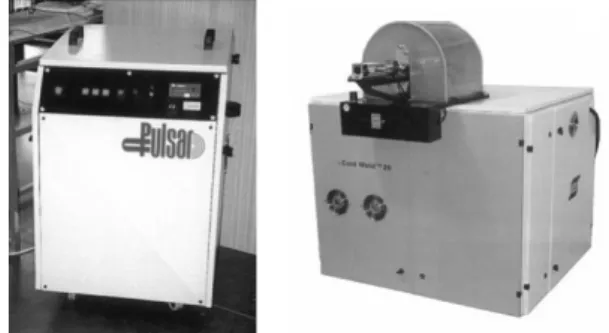
Fig. 4 The magnetic pulse power source from Pulsar6)
류()를 흘리면 매우 강한 자기장
가 발생하며 전 기전도체인 접합재(Outer tube)에 유도전류()가 발 생된다. 두 전류(
)의 상호작용에 의한 반발로 인 한 전자기력
에 의하여 접합이 이루어진다.이때의 전자기력은 식(1)으로서 나타낸다.
(1)
여기서
: Magnetic field intensity(
)
: Magnetic flux density (
) : permeability (
)
이러한 전자기력에 의해 Fig. 2와 같이 접합재는 모 재(inner tube)에 충돌한 후 모재의 항복강도 이상이 되면 접합재는 유체와 같은 흐름을 시작하고 금속젯 (metal jet)에 의하여 용접부 주변의 불순물들은 제거 된다. 빠른 공정속도로 인하여 열 발생이 거의 없음에 도 불구하고 금속학적인 접합이 이루어진다
1).
3. 장 치
성공적인 접합을 위해서는 가공물에 따른 충분한 전 자기력을 얻을 수 있는 장치설계가 중요하다. 일반적으 로 MPW 장치는 Fig. 3과 같이 전자기 발생 전원장 치, 코일 및 자속집중기로 구성된다.
Fig. 4는 Pulsar에서 개발한 전자기 발생 전원장치 로서 동력 공급 장치, 에너지 저장 축전기, 제어회로, 축전기의 코일로의 충격 방전을 위한 스위치장치, 그리 고 전달선과 버스로 구성되었다.
코일(working coil)은 가공물 표면에 순간적으로 고
자기장을 생성시켜 금속을 접합하는데 사용되며 가공의
종류와 가공물의 크기에 의해 결정되는 치수 및 형상,
발생하는 자계의 자속시간과의 관계나 급격한 방전에
의한 콘덴서의 손상을 방지하기 위해 최적의 인덕턴스
를 계산한다. 또한 공정중의 충격력에도 견뎌내며 안전
성을 유지하기 위한 충분한 기계적 강도와 질량을 갖도
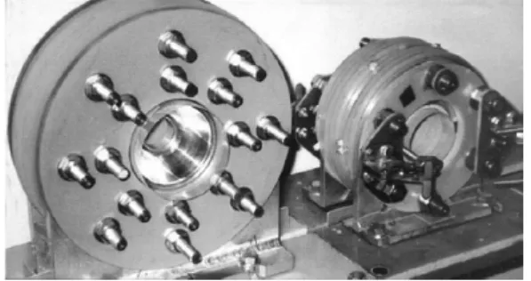
Fig. 5 Examples of coils used for magnetic pulse welding6)
I1 I2 I3
Coil Field Shaper
Workpiece
I1: coil current
I2: primary induced current I3: secondary induced current
I1 I2 I3
Coil Field Shaper
Workpiece
I1 I2 I3
Coil Field Shaper
Workpiece
I1: coil current
I2: primary induced current I3: secondary induced current Fig. 6 Principle of the field shaper
Discharged current(Ka) 800 600 400
200
-200
-400 -600 0
Charged voltage : 156.8kV
0 5 10 15 20 25 30 35 40 45
Time(㎲)
Fig. 7 Discharge current wave form flowing in the inductor coil3)
Charged energy In capacitors Charged energy In capacitors Charged energy In capacitors Charged energy In capacitors
Currents discharged Through a coil Currents discharged Through a coil Currents discharged Through a coil Currents discharged Through a coil
Electromagnetic energy Arrounda coil Electromagnetic energy Arrounda coil Electromagnetic energy Arrounda coil Electromagnetic energy Arrounda coil
Electromagnetic force
Electromagnetic force
Electromagnetic force
Electromagnetic force
Electromagnetic force
Kinematic energy in a tube Kinematic energy in a tube Kinematic energy in a tube Kinematic energy in a tube Kinematic energy in a tube
Colliding Against a core Colliding Against a core Colliding Against a core Colliding Against a core
Collision energy Collision energy Collision energy Collision energy
Induced currents Induced currents Induced currents Induced currents
Fig. 8 Flow chart of energy transitions in MPW2) 록 설계한다. Fig. 5와 같이 일반적으로 기계적 강도가
크고 전기저항이 적은 베릴륨동을 가공하여 사용하며 코일의 형태로는 적용 제품에 따라 외측에서 내측방향 으로 접합되는 솔레노이드 형의 압축 코일(E)과 내측 에 삽입되어 외측방향으로 접합시키는 팽창코일(E) 및 평판의 가공물에 사용되는 평판형 코일(E)을 사용한다6). 자속집중기(field shaper)는 코일과 접합재 사이에 위치하며 코일로부터 전류가 방전되면 전기적 유도 작 용에 의해 접합재로 유도전류를 전달한다. Fig. 6과 같 이 코일에 전류가 흐르면 자속집중기의 외측표면에 코 일의 전류(I1)와 반대방향으로 유도전류(I2)가 생기고, 이 유도전류는 또 다시 자속집중기의 내측표면에 이와 반대반향의 전류를 유도한다. 이 유도전류에 의해 자속 집중기 표면과 모재 사이에 자기장이 형성되고 모재 표 면에 또 다른 반대방향의 유도전류(I3)가 생성되어 접 합이 이루어지게 된다. 이러한 자속집중기를 이용하면 고효율의 전자기력을 얻을 수 있으며 자속집중기의 설 계는 코일과 마찬가지로 가공물의 형상에 적합하게 제 작되어야 한다. 또한 코일과의 전기적 결합상태가 좋아 야 하므로 전기적 특성이 좋고 공정시 충격력을 견딜 수 있도록 기계적 강도가 좋은 재료 선정이 요구된다.
또한 코일과 마찬가지로 베릴륨동이 주로 사용되며 경
우에 따라 경화 알루미늄 합금을 사용한다6).
MPW 공정에 사용되는 금속재는 저항으로 인하여 빠른 속도로 금속내로 자기장이 생성되었다가 결국 0으 로 감소한다. 이를 표피효과라 하며 금속재내로 침투하 는 자기장의 침투가 표피 깊이 (skin depth)에 한정되 어 있으므로 짧은 펄스가 요구된다. Fig. 7과 같은 전 류의 감쇠는 사실상 에너지 손실을 의미하는 것으로 방 전 전류의 최초 반주기만(T/2)을 공정에 이용한다3). 이 때의 전자기력은 용접의 성공여부 및 품질을 결정하 는 핵심요소로써, 최적의 전자기력을 얻기 위해서는 적 용하고자 하는 제품에 적정한 장치설계 뿐만 아니라 공 정변수의 영향에 대한 충분한 고려가 필요하다.
앞에서 언급한 바와 같이 MPW 공정시 최적의 공정 변수의 선정은 접합부의 성능을 좌우한다. 이들 변수로 는 Fig. 8의 에너지 변환 원리에 의하여 방전 전류에 따른 코일의 인덕턴스, 충돌을 위한 충분한 운동에너지 를 얻기 위한 접합재의 D/T(접합재 직경/두께)비, 접 합재와 모재사이의 간격(G)으로 분류한다2).
코일의 인덕턴스는 전자기 에너지로서 역할을 수행하 여 전자기 에너지가 증가할수록 충돌 속도 역시 증가한 다. 따라서 최적의 인덕턴스 값을 가질 때 최대값을 갖 으며 D/T비는 접합재의 소성 작업(plastic work)에 영향을 미치며, 접합재와 모재사이의 간격은 모재에 부 딪혀 충돌하기 전 접합재를 가속하는데 필요하다.
코일의 인덕턴스는 Zhang5)에 의한 계산값과 실험값 의 비교를 통하여 아래의 Grover's 식이 적정함이 증 명되었으며 코일과 접합재 사이의 간격은 1mm가 적정 한 것으로 보고되었다2).
Table 1 Variation of the acceptable limit of gap G(mm) with both of the tube diameter and the numbers of turn of coil2)
D
N 12 15 17.5 20
10 - - 1.5<G<5 1<G<5.5 15 - G=3 1<G<5 1<G<5.5 20 - 2.5<G<4 1.5<G<3.5 G=3
Gap, G(mm)
6
4
2
0
0 2 4 6
Inductance of coil, L(μH)
D=17.5mm
D=20mm
D=15mm
Fig. 9 Combinations of acceptable limits of gap and inductance2)
Contact point
Fig. 10 Description of the joint when welding with MPW7)
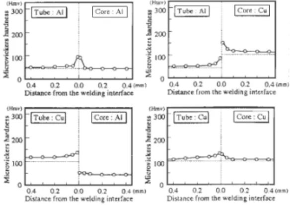
Fig. 11 Hardness profiles of joints with dissimilar materials4)
×
(2)
여기서,
: Inductance : radius of coil
: turn number
: length of coil : permeability
접합재의 D/T비와 접합재와 모재사이의 간격은 Kojima
2)의 실험을 통하여 Table 1.과 Fig. 9에 나타 나있다. 접합재의 직경이 증가하면 더욱 쉽게 용접이 이루어지는 것을 확인할 수 있다. 따라서 D/T비가 클 수록 용접이 더욱 용이함을 알 수 있었다. 또한 인덕턴 스와 접합재와 모재사이의 간격 G가 타원의 중심에 가 장 근접할 때 성공적인 용접수행이 가능함을 확인할 수 있다.
이러한 공정변수에 의하여 충돌 속도가 결정되며 Fig. 10과 같이 충돌점(contact point) 속도( )와 충돌 속도( )는 다음과 같이 표현된다
2).
(3)
여기서,
: contact point velocity : impact velocity
충돌과 동시에 접합재와 모재사이에서 발생된 금속젯 (metal jet)에 의해 접합표면에 존재하는 오염층이 제 거되어 접합에 필요한 청결한 표면이 얻어지며 접합이 이루어지기 때문에 금속젯의 발생은 필수적이다. 일반 적으로 금속젯은 모재와 접합재의 성분으로 이루어지는 데 접합재가 모재에 비해 밀도가 비슷하거나 적을 때는 대부분 접합재의 성분으로 구성된다
8).
5. 접합계면 특성
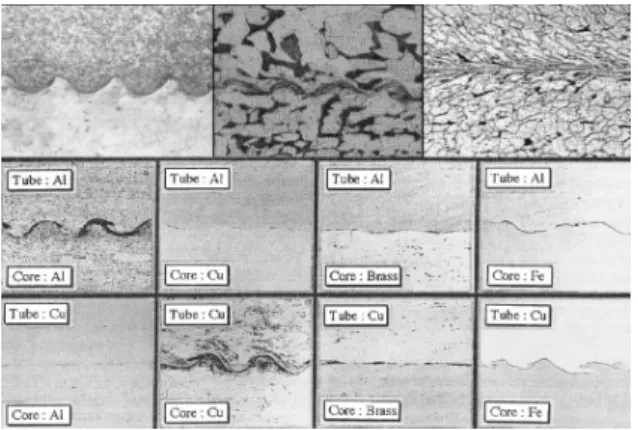
MPW를 이용한 금속접합 시 접합계면에서 경도가 증가함을 Fig. 11을 통해 알 수 있으며, 폭발용접과 유 사한 Fig. 12와 같은 웨이브 패턴(wave pattern)이 발견 되었으며 이를 통하여 두 기술의 원리가 유사함을 확인 할 수 있다.
웨이브 패턴은 접합과정에서 접합재와 모재의 충돌점
에서 발생되는 압력이 접합되는 금속의 전단강도에 비
Fig. 12 Micrographs from interfaces of MPW with different core materials and different tube materials3)
Pocket Pocket
Fig. 13 An example of pocket between flyer and parent plates(both in Al) in MPW3)
Fig. 14 Examples of various components of application of the magnetic pulse welding process7)
Magnesium Steel Nickel Titanium Stainless steel Zirconium Molybdenium Brass Copper Aluminium
M agnesium Steel
N ickel Stainless steel Zirconium M olybdenium B rass C opper A lum inium
Fig. 15 Material combinations that have been successfully welded with the magnetic pulse welding technology7)
해 훨씬 크기 때문에 금속은 유체와 같은 거동을 하여 소성적으로 흐르게 되어 나타난 것으로, 모재에서의 이 동속도가 어떤 임계값 이상인 경우에 생기는데 이 임계 값 이하에서는 접합공정과 관련된 접합변수들이 약간만 변화하여도 접합계면에서 미접합부가 생길 수 있다. 금 속재의 종류에 따라 용접 시 이종금속 심의 경계면에 화합물 층이 발생되었지만 그것의 두께는 2-20㎛로 매 우 적으며 파동의 앞과 뒤쪽 부위에는 Fig. 13과 같이 금속이 고화된 포켓(pocket)이 존재할 수 있는데 이는 금속젯 형성하고 있는 접합재와 모재의 성분으로 이루 어져 있으며 접합과정에서 접합재의 동적에너지 일부가 열로 변함으로 인해 접합계면에서 온도가 급상승하여 금속젯의 일부가 용융되어 급랭된 부분을 나타낸다. 접 합재와 모재가 고용체를 형성할 경우는 연성을 갖게 되 지만 금속간화합물을 형성할 경우에는 매우 취약하여 접합부의 성능에 많은 영향을 끼치게 된다8).
근본적으로 접합계면의 특성은 주요 공정변수인 코일 의 인덕턴스, 코일과 접합재와의 간격 및 접합재와 모 재간의 거리에 의해서 결정되는 동적변수인 속도 및 충 돌각 그리고 접합재의 두께 및 모재와 접합재의 물리적 기계적 성질 등에 좌우되기 때문에 이들의 영향을 충분 히 고려하여 접합변수를 설정하는 것이 중요하다8).
6. 적 용
초기 MPW는 설비산업에서 brazing의 부식 가능성 때문에 이를 대체할 기술의 필요성이 증가함에 따라 개 발되었다. MPW는 접합과 동시에 금속학적 상호작용이 더 이상 이루어지지 않기 때문에 부식의 위험이 적다.
또한 접합 가능성이 부족한 금속간의 접합이 가능하며 금속의 고유저항이 큰 전도성이 작은 금속의 경우 copper driver등과 같은 부속재를 사용하여 접합이 가 능하다. 이러한 이유로 현재 산업에서의 MPW의 적용 은 이종금속의 접합에 초점을 맞추어 더욱 실용적으로 사용되고 있으며 점차 경량화 되어가는 부품산업에서의 본 기술의 적용은 Fig. 14와 같이 자동차의 Al 스페이 스 프레임, 드라이브샤프트 등에 사용되어 부품수의 감 소를 통한 단순화를 통하여 중량감소의 효과를 가져왔다.
또한 MPW 공정은 높은 반복성을 가지고 있어 가공 물에 따른 최적의 공정변수가 결정되면 손쉽게 제어 및 조정이 가능하여 한 시스템의 연간 생산 가능량은 백만 부품 이상으로 보고되고 있다9). Fig. 15는 현재까지 보고된 MPW을 이용한 다수의 금속 접합 여부를 나타
낸다.
비록 아직 다루어지지는 않았지만 최근 개발된 초고 강도스틸(Ultra high strength steels)의 접합도 가 능할 것으로 보고되고 있다9). 이러한 스틸은 용접 작업 시 발생하는 열에 반응하기 때문에 이를 고려한 설계가 필요하지만 본 기술은 고상용접공정(Cold welding process)으로 적용이 가능하다.
7. 결 언
본 고에서는 MPW의 원리, 장치, 공정변수, 접합계 면 특성 및 적용에 대하여 기술하였다.
MPW는 생산성 및 품질향상측면에서 큰 장점을 가 지고 있으며 응용분야가 매우 다양한 용접법으로 선진 외국의 산업체를 중심으로 자동차, 가전 등의 분야에서 본 기술에 대한 산업적 응용에 대한 연구가 진행 중이 다. 따라서 국내에서 MPW에 대한 기초적인 이론적, 실험적 연구와 이의 응용에 대한 관심을 기울여야 할 것으로 사료된다.
참 고 문 헌
1. B.T. Spitz and V. Shribman : Magnetic pulse welding for tubular applications, The Tube & Pipe Journal, 11-2 (2000), 32-34
2. M. Kojima and K. Tamaki : Electromagnetic welding of tube, The 5the International symposium of the japan welding society, Aprial (1990), 201-206 3. H. Hokari, T. Sato, K. Kawauchi, and A. Muto :
Magnetic Impulse Welding of Aluminium Tube and Copper Tube with Various Core Materials. Welding International, 12-8 (1998), 619-626
4. D. Dudko, V. Chudakov, L. Kistersky and T. Barber : Magnetic pulse welding of tubing, Exploring the cold welding process, Fabricator, 26-8 (1996), 62-66 5. P. Zhang : Joining Enabled by High Velocity
Deformation, The Degree Doctor of Philosophy in the Graduate School of the Ohio State University (2003), 183-200
6. J.S. Lee : Electro-magnetic forming, KSME, 28-5 (1988), 476-486
7. V. Shribman : Take Advantage of the New Magnetic Puls Welding Process, Svetsaren, 56-2 (2001), 14-16
8. B.Y. Kang and H.J. Kim : Theory and Characteristics of Explosive Welding, Journal of the korean welding society, 11-3 (1993), 1-9
9. A. Kochan : Magnetic Pulse Welding Shows Potential for Automotive Applications. Assembly Automation, 20-2 (2000), 129-132
10. J.F. Erdmann : The Basic Fundamentals of Magnetic Pulse Welding, Schweissen und Schneiden, 19-1
(1967), 2-8
11. M. Pezzutti, : Innovative Welding Technologies for the Automotive Industry, Welding Journal, 79-6 (2000), 43-46
12. J. Pearson : Advanced High Energy Forming, Explosive Welding, ASTME, (1961), 60-159.
13. G. Hurshal : Bonding of Aluminum by the capacitor discharge magnetic forming processes, Welding Journal, 46 (1967), 507-510
14. Y.A. Sergeeva, V.A. Chudakov and G.N. Gordan : Examination of the transition zone in magnetic pulse welded joints between aluminum and copper, Paton welding journal 1-12 (1989), 874-877
15. K.K. Botros and T.K. Groves : Fundamental impact-welding parameters an experimental investigation using a 76-mm powder cannon, Journal of applied physics, 51-7 (1980) 231-241 16. G.R. Cowan, O.R. Bergmann, and A.H. Holtzman :
Mechanism of bond zone wave formation in explosive clad metals, Metallurgical Transactions, 2 (1971), 3145-3155
17. G.R. Cowan and A.H. Holtzman : Flow configuration in colliding plates explosive bonding, Journal of applied physics, 34-4 (1963), 928-939
18. D.R. Chichili, K.T. Ramesh and K.J. Hemker : The High-Strain-Rate Response of Alpha-titanium:
experiments, deformation mechanism and modeling, Acta material, 46-3 (1998), 1025-1043
19. G.G. Corbett, S.R. Reid, and W. Johnson : Impact loading of plates and shells by free-flying projectiles: A Review, International Journal of Impact Engineering, 18-2 (1996), 141-230
20. A. Turgutlu, S.T. Al-Hassani, and M. Akyurt : The influence of projectile nose shape on the morphology of interface in impact spot welding, International Journal of Impact Engineering, 18-6 (1996), 657- 669
21. N. Takatsu, M. Kato, K. Sato, T. Tobe : High speed forming of metal sheets by electromagnetic force, Jpn. Soc. Mech. Eng. Int. J., 31-1 (1988), 14 22. D. H. Birdsall, F.C. Ford, H.P. Furth and R. E.
Riley : Magnetic Forming, Am. Mach./Metalworking Manuf, 105 (1961), 117-121
23. E.J. Bruno : High Volecity Foriming of Metals, ASTME, 55
24. W.F. Brown, J. Bandas and N.T. Olson : Pulsed magnetic welding of breeder reactor fuel pin end closures, welding journal, 57-61 (1978), 22-26 25. S.H. Lee and D.N. Lee : Estimation of magnetic
pressure in tube expansion by electromagnetic forming, Journal of Materials Processing Technology, 57 (1996), 311-315
26. J. Bednarczyk : Distributions of forces in the inductors used in metal processing in the pulse magnetic field, Journal of Materials Processing Technology, 133 (2003), 340-347
27. A.A. Tamhane, M.M. Altynova and G.S. Daehn :
Effect of sample size on ductility in electromagnetic ring expansion, Scripta Materialia, 34 (1996), 1345-1350
28. H.G. Baron and R.H. Henn : Springback and Metal Flow in forming shallow dishes by explosives, Int.
Journal of Mechanical Sciences, 6 (1964), 435-444 29. G.K. Fenton : Development of numerical tools to
model plasticity in aluminum due to electromagnetic forces, M.S. Thesis, Ohio State University, This thesis contains detailed information on the CALE code, (1996)
30. A.G. Bogle : Effective inductance and resistance of screenede coils. J. Inst. E. E., 878 (1940), 299- 316
31. V. Shribman : Take advantage of the new magnetic puls welding process, Svetsaren, 56/2-3 (2001), 14-16
32. M. Kaltenbacher, H. Landes and R. Lerch : An efficient calculation scheme for the numerical simulation of coupled magneto mechanical systems, IEEE Trans. Magnetic, 33 (1997), 1646-1649 33. G.A. Dilts : Moving least squares particle hydro
dynamics. II. Conservation and boundaries, Int. J.
Numer. Meth. Eng., 48 (2000), 1503-1524
34. W. H. Drysdale, J.D. Powel, B.P. Burns and A. E.
Zielinski : A survey of codes for modeling electro magnetic launching, Army Research Laboratory Report, ARL-MR-64 (1993)
35. G. Hainsworth, P.J. Leonard, D. Rodger and C.
Lyden : Finite element modeling of magnetic compression using coupled electromagnetic structural codes, IEEE Trans. Magn., 32 (1996), 1050-1053
∙강봉용(姜奉龍)
∙1960년생
∙한국생산기술연구원,정밀접합팀
∙용접전원파형제어,용접재료개발
∙e-mail : [email protected]
∙심지연(沈志娟)
∙1980년생
∙한국생산기술연구원,정밀접합팀
∙전자기 펄스 용접 공정
∙e-mail : [email protected]
36. K.T. Hsieh : A Lagrangian formulation for mechanically, thermally coupled electromagnetic diffusive processes with moving conductors, IEEE Trans. Magn., 31 (1995), 604-609
37. K.T. Hsieh and B.K. Kim : One kind of scaling relations on electro mechanical systems, IEEE Trans. Magnetic, 33 (1997), 240-244
38. Dana Corporation : Magnetic Pulse welding Process To Decrease Vehicle Weignt and Increase Fuel Efficiency, Research and data for Status Report, (2001)
39. M. Kaltenbacher , H. Landes and R. Lerch : A strong coupling model for the simulation of magnetomechanical systems using a predictor/ multicorrector algorithm, Appl. Comput. Electromagnetic. Soc. J., 12 (1997), 102–106
40. B. Bendjima, K. Srairi and M. Féliachi : A coupling model for analysing dynamical behavior of an electromagnetic forming system. IEEE Trans.
Magnetic, 33 (1997), 1638-1641
41. F. Azzouz, B. Bendjima, M. Féliachi and M.E.
Latréche : Application of macro-element and finite element coupling for the behavior analysis of magnetoforming systems. IEEE Trans. Magnetic, 35 (1999), 1845-1848
42. N. Takatsu , M. Kato and K. Sato : High-speed forming of metal sheets by electromagnetic force, JSME Int. J., 31 (1988), 142-148
43. G.K. Penton and G.S. Daehn : Modeling of electro magnetically formed sheet metals, J. Mater.
Process. Technology, 75 (1998), 6-16
∙강문진(姜紋珍)
∙1963년생
∙한국생산기술연구원, 정밀접합팀
∙용접지능제어, 용접기기개발
∙e-mail : [email protected]
∙김인주(金麟柱)
∙1968년생
∙한국생산기술연구원 지능형부품소재센터
∙용접공정제어
∙e-mail : [email protected]