Extraction of Ground Control Points from TerraSAR-X Data
Jeong-Won Park1, Sang-Hoon Hong2, and Joong-Sun Won1
1 Department of Earth System Sciences, Yonsei University [email protected]
2 Division of Marine Geology and Geophysics, University of Miami
ABSTRACT: It is possible to extract qualified ground control points (GCPs) solely from SAR data without published maps. TerraSAR-X is now in orbit and provides valuable data that have one of the highest spatial resolutions among civilian SAR systems. In this study, a sophisticated method for GCP coordinate extraction from TerraSAR-X stripmap mode data with a 3 m resolution was tested and the quality of the extracted GCPs was evaluated. An inverse-geolocation algorithm was applied to obtain GCPs from TerraSAR-X data. SRTM 90m DEM was used as an auxiliary data set for azimuth time correction of the SAR data. Mean values of the distance errors were 0.11 m and -3.96 m with standard deviations of 6.52 m and 5.11 m in easting and northing, respectively. The result is one of the best among GCPs possibly extracted from current civilian remote sensing systems. The extracted GCPs were used for geo-rectification of an IKONOS image, which demonstrated the applicability of the GCPs to geo-rectification of high resolution optic image.
The method used in this study can be applied to KOMPSAT-5 for geo-rectification of high-resolution optic images acquired by KOMPSAT-2 or follow-up missions.
KEY WORDS: TerraSAR-X, inverse geolocation algorithm, ground control point (GCP), SAR, geo-rectification.
1. INTRODUCTION
The conventional SAR geolocation algorithm, that derives geographic coordinate by solving three equations (range equation, Doppler equation and equation of Earth ellipsoid) and is called the range-Doppler geolocation algorithm, produces geometrical errors caused by its assumption of an ellipsoidal earth model. The method, however, disregards topographic effects on the Earth surface, which causes positioning error, especially more in easting than in northing. Thus GCPs derived by the range-Doppler algorithm cannot avoid planimetric errors caused by actual terrain relief and are limited to a projection to an Earth ellipsoid. The accuracy of GCPs derived from SAR image can be improved by using accurate DEM and precise orbit data. Hong et al. (2006) proposed an inverse-geolocation algorithm that is based on SAR simulation technique and accommodate topographic effects. In their study, the inverse- geolocation algorithm was applied to ERS image with SRTM DEM, and achieved GCPs with about 10 m accuracy.
This study is focussed on extraction of GCPs by applying the inverse-geolocation alogorithm to the high resolution TerraSAR-X data which released to public recently, and on assessment of the accuracy of extracted GCPs. The extracted GCPs are used for geo-rectification of an IKONOS image, which demonstrates the applicability of the GCPs to geo-rectification of high resolution optic images. Precise extraction of GCPs is one of the principal techniques that can be used for improving accuracy on various SAR applications. The method used in this study can be applied to KOMPSAT-5.
2. INVERSE-GEOLOCATION ALGORITHM The range-Doppler geolocation algorithm converts image coordinates (range pixel number, azimuth line number) to Cartesian coordinates (X, Y, Z). The accuracy of the geolocation algorithm depends on the sensor position, velocity vector, pulse delay time and target height (Curlander and McDonough, 1991). If the information on satellite position and imaging time is accurate, the geolocation errors are only due to the target height. However, the errors caused by object height cannot be accommodated without further processing.
Conversely, the inverse-geolocation algorithm is an inverse projection from the Earth surface to radar image coordinate, and thus is possible to accommodate topographic effects by exploiting DEM. Terrain correction methods for geocoding SAR image were developed by several researchers (i.e. Schreier et al. 1990, Wivel et al. 1992, Olmsted 1993). Liu et al.(2004) applied a SAR simulation technique for correction of positional errors in maps and DEMs. On the other hand, in the inverse-geolocation algorithm, SAR simulation is used for correction of imaging time under an assumption that there are no systematic positional errors in DEM.
Olmsted (1993) introduced following equations (1)-(3) to determine a correct image time:
] / ) ( /[df t0 dt df
t=Δ D D
Δ (1)
where ΔdfD= fD(t)−fDC, fDCis Doppler centroid and fD(t) is Doppler shift as a function of time.
At the time when the radar beam centroid intersects a surface point, the Doppler frequency shift equals the Doppler centroid such that (Liu et al., 2004)
(
() ()) (
() ())
0) ( ) 2
( − DC = s − p ⋅ − − DC =
D V t V t S t P t f
t f R
t
f λ (2)
The imaging time t for the DEM pixel P(t) can be determined by solving equation (2). However, equation (2) is a nonlinear equation with respect to the time t , and it is difficult to obtain an explicit solution to the equation.
Time derivatives of the equation (2) is given by
⎟⎟
⎟⎟
⎠
⎞
⎜⎜
⎜⎜
⎝
⎛
−
⋅
− −
− +
−
⋅
−
= 2 2
) (
)) ( ) ( ( )) ( ) ( ) ( ( ) (
)) ( ) ( ( )) ( ) ( (
) ( 2 ) (
t R
t V t V t P t t S V t V
t A t A t P t S t R dt
t df
p s p
s
p s D
λ
(3) where A and s A are satellite and target acceleration p vectors, respectively. The solution to equation (1) can be achieved by applying the Newton-Raphson iteration method to equations (1) and (3). The solution presents Doppler shift satisfying equation (2). The first step is to calculate Δt with a give initial value t (initial scene 0 centre time) using equation (1) and (3). The time is then updated by t1=t0+Δt. A new Δt is again calculated with the updated time t for the next iteration until it 1 converges to a critical value of time parameters. The imaging time t determined by the iteration is converted to the azimuth line number given by
) ( pixel
Azimuth =PRF× t−ta (4)
where PRF is the pulse repetition frequency and t is the a time of the first azimuth line provided by the SAR system.
The slant range distance R(t) between the satellite and target position is then corrected by equation (1) with the updated imaging time t . The corrected range pixel number is then given by
⎟⎠
⎜ ⎞
⎝
⎛ −
×
×
= tr
c t RSR R() 2
pixel
Range (5)
where RSR is the range sampling time, c is the velocity of the light and t is the time of the first range pixel or r range gate at near range.
To solve equations (2) and (3), the radar position vector is required as an input parameter. The DEM is used for P(t) values in equation (3). To ensure the convergence and to improve computational efficiency, we set up critical values: 1×10⁻⁷m and 1×10⁻¹⁰s for the position vector and imaging time, respectively. The SAR simulation is adopted to find an azimuth time satisfying the Doppler frequency shift equal to the Doppler centroid.
The Doppler centroid of the TerraSAR-X image used in this study was close to zero. When the imaging time is
obtained in this way, the range time can easily be calculated from the radar range R(t).
3. DATA AND PRE-PROCESSING 3.1 TerraSAR-X Image and SRTM DEM
A TerraSAR-X single-polarization stripmap mode SLC image was acquired over Gunsan area, Korea, on 9 December 2007. The precision (1σ) of orbit state vector of TerraSAR-X is divided in three types: 700 m for predicted orbit, 2 m for rapid orbit and 20 cm for science orbit. The science orbit was used in this study since high- precision satellite positioning is crucial in geolocation algorithm. The accuracy of the extracted GCPs is also affected by the quality of DEM used. In this study, SRTM DEM was used for simulating most generalized case. The horizontal and vertical accuracies of SRTM DEM in Asia are 8.8 and 6.2 m, respectively, with 90 % linear errors (Rodriguez, 2005). However, SRTM DEM which generated by radar interferometry has a large number of voids due to geometrical characteristics of radar system.
Because these voids possibly cause significant errors of extracted GCPs, they were filled by merging data with the GTOPO-30 DEM. In the case of 40 degrees on incidence angle and 6 m errors on DEM elevation, the theoretical geolocating error achieved by conventional range- Doppler algorithm is about 7 m on the surface of Earth ellipsoid (TerraSAR-X basic product manual, 2008).
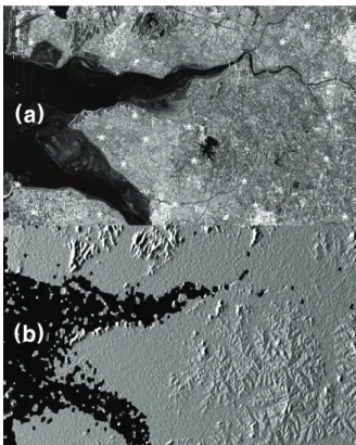
Figure 1. (a) TerraSAR-X image and (b) a simulated SAR image. The GCPs extracted by the tested method are denoted by white stars on (a). The simulated SAR image was created by SRTM DEM.
3.2 Range and Azimuth Time Correction
The recoded SAR system parameters of pulse delay time and azimuth imaging time usually have notable errors. The time errors cause positional errors of satellite in geocoding process, and degrade the accuracy of extracted GCPs. In other words, the time errors lead to incorrect antenna position and consequently positional errors of the pixel. In this case, the geographic coordinate of extracted GCPs shows systematic drift from north to south and/or from east to west. DEM also has positional errors on each point but the overall drift is negligible.
Thus, systematic drift in SAR image due to the time errors can be corrected by matching to the DEM.
The inverse-geolocation algorithm transforms geographic coordinate of each selected point in DEM into each image pixel and results in more accurate geographic coordinates for GCPs in a SAR image by exploiting topographic relief, while the range-Doppler geolocation algorithm transforms each image pixel into ground Cartesian (X, Y, Z) coordinate. The inverse geolocation algorithm requires the SAR simulation which employs a DEM, orbit data, SAR system parameters including PRF, sampling rate and Doppler centroid. The time errors can be corrected by calculating the offsets between the real SAR image and the simulated image. Two-dimensional cross-correlation over the full scene is performed to estimate the offset and the location of peak is related to the offset between two images. The higher the DEM resolution is, the more precise time correction is possible.
Figure 1(a) shows the TerraSAR-X image and figure 1(b) shows the simulated image by using SRTM DEM and SAR system parameters.
4. TEST RESULTS AND DISCUSSION We extracted 22 GCPs from TerraSAR-X image by applying the inverse-geolocation algorithm. Theextracted geographic coordinates were compared with reference geographic coordinates obtained from the digitized Korean national contour map with a scale 1:25,000 for accuracy assessment. The Transverse Mercator projection and the Tokyo datum are used for attaching geographical coordinates on GCPs.
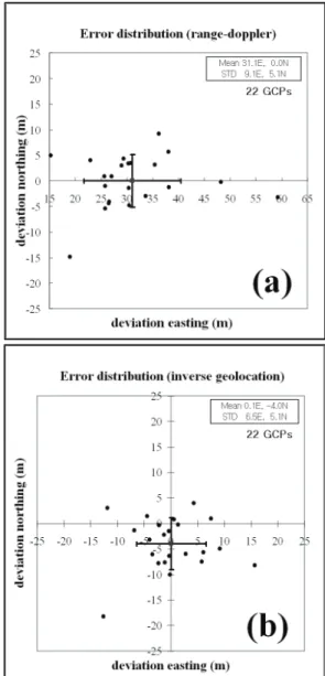
The range-Doppler algorithm and the inverse- geolocation algorithm were equally applied for performance assessment. Figure 2(a) and 2(b) show the error distribution of obtained GCPs through the range- Doppler algorithm and the inverse-geolocation algorithm, respectively. An averaged value is plotted as a square with error bars calculated from standard deviations.
In the results of the range-Doppler algorithm, the mean errors in northing and easting were 0.03 and 31.08 m with standard deviations of 5.13 and 9.40 m, respectively.
Shifts in the easting are much greater than those for northing. Since the averaged horizontal error is greater than the pixel size of Landsat ETM+, the range-Doppler algorithm is not suitable for GCP extraction. It is natural for the range-Doppler algorithm to cause significant
errors in easting direction, because the terrain effects are not accounted for.
Figure 2. Error distribution of the extracted GCPs obtained by (a) the range-Doppler geolocation algorithm and (b) the inverse-geolocation algorithm.
The inverse-geolocation algorithm was tested in two ways: one with and without the time correction procedure.
The average of the errors without time correction was found to be -1.87 and 24.19 m with standard deviations of 4.87 and 6.55 m, respectively. The standard deviation specifically in easting is better than that from the range- Doppler algorithm, which proves the improved performance by adopting topographic relief. However, there is still systematic shift in extracted GCPs. To include time correction procedure, the offsets induced by errors in pulse delay time and azimuth start time are corrected as described in section 3.2. Since the spatial resolution of TerraSAR-X image is about thirty times better than that of SRTM DEM, the convergence of compensation time in Newton-Raphson iteration described in section 2 is not easy. Especially in the areas
where topographic relief is very smooth, the possibility of convergence is so low that we utilized only a part of entire scene where topographic relief is distinct for two- dimensional cross-correlation. The estimated offset was 11.185 pixels (or 5.0894×10⁻⁸s) in range and -1.293 pixels (or −3.3888×10⁻⁴s) in azimuth. The average of the errors after time correction was found to be -3.96 and 0.11 m with standard deviations of 5.11 and 6.52 m in easting and northing, respectively. The results clearly show that the systematic shifts induced by incorrect imaging time can be reduced by adopting time correction procedure. Since the averaged accuracy of extracted GCPs was lower than 4 m and the standard deviation was about 6.5 m, utilizing the TerraSAR-X image through the inverse-geolocation algorithm is the best method for extracting GCPs with high reliability among all civilian satellite remote sensing data. This method can be applied effectively to specific foreign areas where no reliable map is available.
The extracted GCPs are used for geo-rectifying high resolution optic images after all. In the same spatial resolution, since the spatial resolving power for common targets in optic image is better than that in SAR image, a high resolution optic image geocoded by the method described in this study can play a role of a high resolution map. Figure 3 shows a geo-rectified IKONOS image over a part of areas covered by TerraSAR-X image overlaid with a national digital map. Seven GCPs extracted from TerraSAR-X image was used for geo-rectification. As shown in the figure 3, there is a good agreement between the reference vector map and the geo-rectified image.
Consequently, the obtained GCPs from TerraSAR-X image can be utilized for high resolution optic images.
Figure 3. Geo-rectified IKONOS image overlaid with national digital map. The IKONOS image was geo-rectified using the GCPs extracted from the TerraSAR-X data.
In order to apply this concept to KOMPSAT-5, additional experiments in various areas are needed. As described before, this approach is governed by the accuracies of DEM and SAR system parameter including orbit data. First of all, it is difficult to predict the orbit accuracy of KOMPSAT-5 now. The accuracy test for various kind of DEM and for a function of target height, however, is possible with TerraSAR-X data. In this study,
we employed SRTM DEM which can be available for almost everywhere in the world as the most generalized case. If there are various DEMs available on target area, more precise extraction of GCPs will be possible.
Concerning to the target height, the Gunsan area where we tested in this study has relatively low height and smooth topographic relief, but GCP extraction on topographically rough and high altitude area may results in severe errors. Thus, the accuracy analysis on various topographic effects is needed on further study.
5. CONCLUSION
Precise GCPs are crucial for geolocation of remotely sensed imagery. For regions where inaccessible or no published map is available, GCPs can be obtained from high resolution SAR image. In this study, precise GCPs were obtained from the high resolution TerraSAR-X stripmap mode image and SRTM DEM by employing inverse-geolocation algorithm. Mean values of the errors in the extracted GCPs were 0.11 and -3.96 m with standard deviations of 6.52 and 5.11 m in easting and northing, respectively. This is one of the most precise results in extraction of GCPs from civilian satellite remote sensing. Comparatively accurate geo-rectifying on IKONOS image was possible by using the extracted GCPs. The method used in this study can be proposed as an application technique for KOMPSAT-5, and maximize the operational synergy of KOMPSAT-2 and KOMPSAT-5.
ACKNOWLEDGEMENT
This work was funded by Korea Aerospace Research Institute within the framework of Development of KOMPSAT-5 system. The TerraSAR-X data were provided to the author J.-S. Won as a TerraSAR-X Science Team Project (PI No. COA0047).
REFERENCES
Curlander, J.C. and McDonough, R.N., 1991, Synthetic Aperture Radar, System and Signal Processing, pp. 372-387, New York, John Wiley &
Sons.
Hong, S.-H., H.-S., Jung and J.-S., Won, 2006, Extraction of ground control points (GCPs) from synthetic aperture radar images and SRTM DEM, International Journal of Remote Sensing, 27(18-20), 3813-3829.
Liu, H., Z. Zhao. and K.C., Jezek., 2004, Correction of positional errors and geometric distortions in topographic maps and DEMs using a rigorous SAR simulation technique, Photogrametric Engineering and Remote Sensing, 70, pp. 1031-1042.
Mohr, J.J. and Madsen, S.N., 1999, Automatic generation of large scale ERS DEMs and displacement maps. In FRINGE'99, 10-12 November 2000, Liege, Belgium, ESA SP-478.
Olmsted, C., 1993, Alaska SAR Facility Scientific SAR User's Guide, ASF-SD-003
Rodriguez, E., 2005, A global assessment of the SRTM accuracy,
Available at: http://eros.usgs.gov/conferences /SRTM/presentations/abstract04_rodriguez.pdf
TerraSAR-X Ground Segment Basic Product Specification Document, 2008, Available at: http://www.
dlr.de/tsx/documentation/SAR_Basic_Products.pdf