두개의 브랜치 라인을 갖는 와이파이 이동통신용 이중 대역 모노폴 안테나의 설계와 제작
정계택*․주영림**․윤중한***
Design and Fabrication of Dual-band Compact Monopole Antenna with Two Branches for Wi-Fi Mobile Applications
Gye-Taek Jeong
*․Young-Rim Ju
**․Joong-Han Yoon
***요 약
본 논문에서는 두개의 브랜치 라인을 갖는 와이파이 이동통신용 이중 대역 모노폴 안테나를 설계 및 제작 하였다. 제안된 안테나는 평면형 모노폴 설계를 기본으로 두 개의 브랜치 방사 선로를 구성함으로서 이중대 역 특성을 갖도록 설계하였다. 제안된 안테나의 접지면 크기는 전형적인 셀룰라 ㅋ폰의 접지면에 적합하게 설계하여 이동통신용 단말기의 PCB와 호환될 수 있도록 하였다. 제안된 안테나는 최적화된 파라메타을 얻기 위해 상용 툴(CST)을 사용하여 시뮬레이션 하였으며 얻어진 최적화된 수치를 이용하여 제안된 안테나를 제 작하였다. 제작된 안테나는 와이파이 이동통신의 동작하는 상위 주파수 대역과 하위 주파수 대역에서 반사손 실, 이득, 방사패턴의 특성을 측정하였다.
ABSTRACT
This letter describes a dual-band compact monopole antenna with two branches for Wi-Fi applications. The proposed antenna is based on a planar monopole design, and composed of two branches of radiating patches for dual-band operation. The ground size of the antenna matches the ground size of a typical hand-held cellular phone for improved compatibility with mobile phone printed circuit boards. The antenna is designed using a simulator and fabricated with optimized parameters. The fabricated antenna is measured at the lower and higher operating frequencies, and the return loss coefficient, gain, and radiation patterns are determined.
키워드
dual-band antenna, two branches, monopole antenna, Wi-Fi application 이중대역 안테나, 두개 브랜치, 모노폴 안테나, 와이파이 응용
* 인하대학교 정보통신공학과([email protected]) *** 교신저자 신라대학교 전자공학과([email protected])
** 인하대학교 전자공학과([email protected])
접수일자 : 2012. 10. 25 심사(수정)일자 : 2013. 01. 15 개제확정일자 : 2013. 01. 21
I. INTRODUCTION
Portable wireless communication devices are beco- ming increasingly inexpensive, small, and thin, and
offer a growing variety of functions. As a result,
several antennas must be installed in a single
hand-held mobile phone. Lightweight, compact
antennas are required for this purpose, since the
available installation space continues to diminish.
However, antenna miniaturization is not an easy task, since gain and bandwidth are bounded by fundamental limits that depend on the size of the antenna. One technique for minimizing the size of an antenna involves the use of a substrate with high permittivity and the insertion of a parasitic element [1]-[3]. However, this approach raises the manu- facturing cost and increases the difficulty of fabricating the antenna structure, thereby precluding the possibility of mass production. Another approach is to alter the geometry of the antenna without increasing the manufacturing cost or complexity.
User demand for Wi-Fi applications has been increasing, owing to innovations in wireless communication technology. However, since Wi-Fi applications operate in dual frequency bands (2.4 – 2.485 GHz and 5.15 – 5.35 GHz), practical applications require a dual-band antenna. There have been a number of studies of such antennas [4]-[15], but existing designs cannot be readily applied to hand-held cellular phones because of the mismatch between the ground sizes of the antenna and the device. Therefore, it is necessary to develop a new type of antenna for application to hand-held cellular phones.
To resolve these issues, this letter introduces a dual-band compact monopole antenna for Wi-Fi mobile applications. The ground size of the pro- posed antenna matches the practical bar type mobile phone ground size. The new antenna is designed by altering the geometry to minimize the size without increasing the manufacturing cost or the difficulty of fabrication, while operating in the required dual-frequency band.
II. ANTENNA DESIGN
The goal of the proposed antenna design is to cover the dual Wi-Fi operating frequency bands. Figure 1
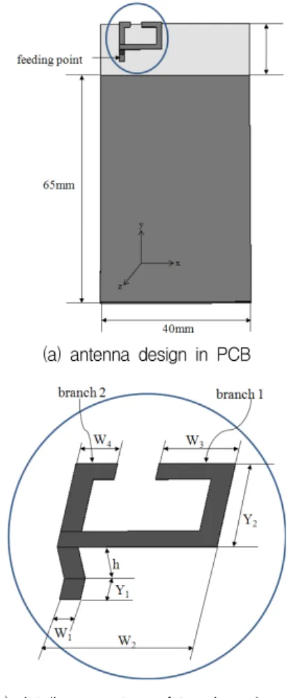
shows the geometry of the new antenna. The antenna is designed on a low-cost FR4 substrate (which is typically used for printed circuit boards (PCBs) in industry), with a thickness of 0.8 mm and a relative permittivity 4.4. It is composed of two branches of radiating patches, with resonant frequencies of 2.4 GHz and 5.2 GHz. The size of the entire substrate with ground is 40 mm⨉80 mm, which is the PCB size of a typical hand-held cellular phone. The copper underneath the antenna is eliminated to obtain a broad impedance bandwidth at lower operating frequencies, by reducing the parasitic capacitance.
(a) antenna design in PCB
(b) detail parameters of two branches in proposed antenna
Fig. 1 Geometry of the proposed antenna with two
branches
First of all, the proposed antenna design covers the lower operating band with branch 1 only. The path length of branch 1 is approximately λ/4 in the lower operating frequency band. Figure 2 shows the return loss coefficient for branch 1 only. Based on the impedance bandwidth, it can be seen that the lower Wi-Fi band is covered.
Fig. 2 Return loss coefficient of the antenna with only branch 1.
When branch 2 is inserted, a second resonance occurs in the higher operating frequency band. Based on the aforementioned observations, the optimized dimensions of the proposed antenna are found using the commercial three-dimensional electromagnetic simulator CST Microwave Studio (MWS). Figure 3 shows the return loss coefficient for various branch 2 lengths when branches 1 and 2 coexist. The influence of branch 2 is fairly significant in the higher operating frequency band, but is hardly felt in the lower frequency band. This makes it easy to simplify the design of the dual-band antenna.
Fig. 3 Return loss coefficient of the proposed antenna for various branch 2 lengths
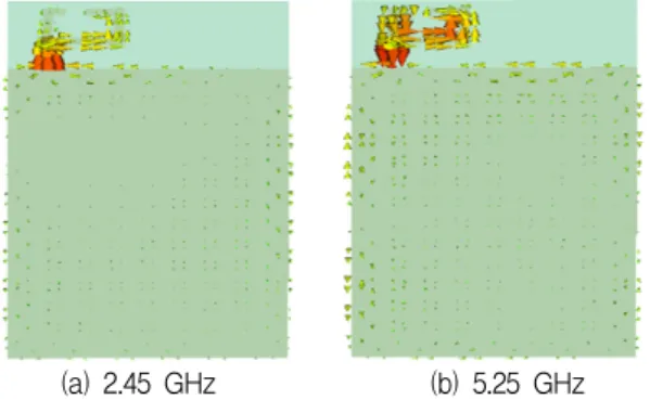
Figure 4 shows the surface current distribution of the proposed antenna in the lower and higher operating frequency bands, again using the EM simulator CST MWS. Figure 4(a) indicates that there is very little current in branch 2 in the lower operating frequency band. This is in agreement with Fig. 3, which indicates that branch 2 has virtually no influence on the lower frequency band.
Figure 4(b) shows that both branches 1 and 2 affect the higher operating frequency band. Acco- rdingly, it is important to preselect a design that operates in the lower frequency band when only branch 1 is used.
(a) 2.45 GHz (b) 5.25 GHz Fig. 4 Surface current distribution of the proposed antenna in the lower and higher operating frequency
bands
III. FABRICATION AND MEASUREMENT RESULTS
A prototype of the proposed dual-band antenna
is fabricated using the optimized parameters
mentioned above. The size of the entire substrate
on which the antenna is fabricated with ground is
40 mm⨉80 mm. The copper underneath the
antenna is etched to obtain a broad impedance
bandwidth at lower operating frequencies by
reducing the parasitic capacitance. The optimized
parameter values are W
1= 1.5mm, W
2= 11.5mm,
W
3= 5.5mm, W
4= 3mm, Y
1= 8mm, Y
2= 2mm,
and h = 3mm. The planar radiating patch size is
11.5mm⨉8 mm, which is very small. It is similar to a conventional chip antenna at the operating frequency of 2.4 GHz. The height h = 3 mm is chosen to obtain a wide impedance bandwidth.
Although this height increases the volume slightly, it does not create a problem because it is less than the thickness of a typical hand-held cellular phone.
Other components of a mobile device, such as antennas for different bands, receivers and cameras, can be installed in the empty space on the right-hand side of the radiating patch.
Figure 5 shows the simulated and measured results for the return loss coefficient of the proposed antenna, and indicates good agreement between them. The measured fractional bandwidth is 18.9% (2.29 – 2.77 GHz) in the lower operating frequency band and 8.5% (5.08 – 5.53 GHz) in the higher operating frequency band.
Fig. 5 Return loss coefficient simulated and measured.
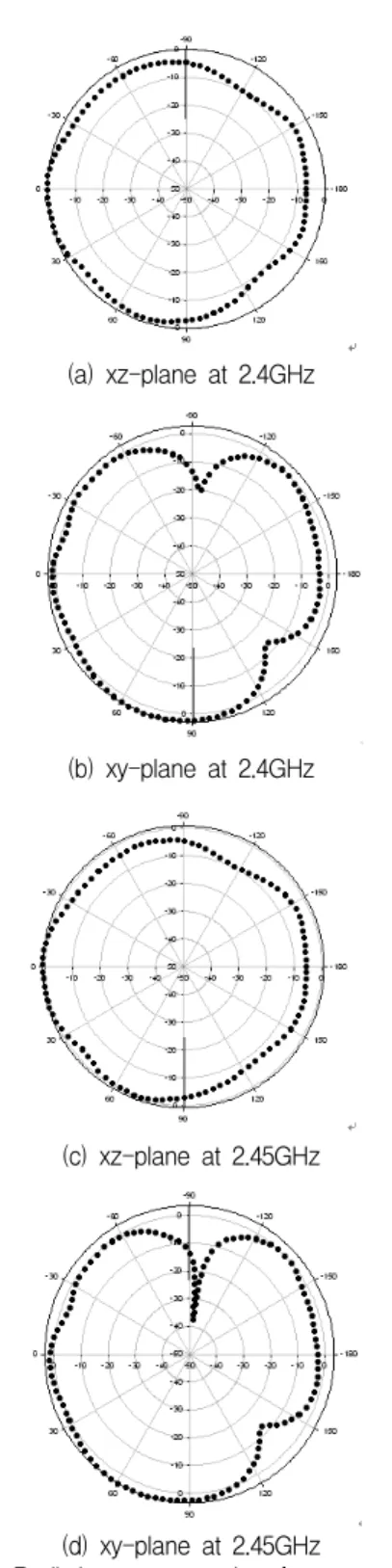
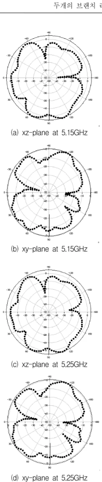
Figure 6 shows the radiation patterns of the fabricated antenna at 2.4 and 2.45 GHz in the xz-plane and xy‑plane. Figure 7 shows the radiation patterns of the fabricated antenna at 5.15 and 5.35 GHz in the xz-plane and xy‑plane. The measured peak gains of the fabricated antenna are 3.5 dBi at 2.45 GHz and 4.6 dBi at 5.25 GHz, all of which are appropriate for Wi-Fi applications. The fabricated antenna exhibits an omnidirectional radiation pattern, which is an important characteristic of an antenna for a hand-held cellular phone.
(a) xz-plane at 2.4GHz
(b) xy-plane at 2.4GHz
(c) xz-plane at 2.45GHz
(d) xy-plane at 2.45GHz
Fig. 6 Radiation pattern at low frequency band
(a) xz-plane at 5.15GHz
(b) xy-plane at 5.15GHz
(c) xz-plane at 5.25GHz
(d) xy-plane at 5.25GHz
Fig. 7 Radiation pattern at high frequency band
IV. CONCLUSION
A dual-band compact monopole antenna with two branches is proposed for Wi-Fi hand-held cellular phones. The proposed antenna is based on a planar monopole design, and is composed of two branches of radiating patches for dual-band operation. Branch 2 hardly influences the lower band, which makes it easy to design an antenna that operates in dual bands. The ground size of the proposed antenna matches the ground size of a typical hand-held cellular phone for improved compatibility with mobile phone PCBs. The antenna is designed using a simulator and is fabricated with optimized parameters. The size of the radiating patch of the fabricated antenna is 11.5 mm⨉8 mm, which is very small. The measured gains of the fabricated antenna are 3.5 dBi at 2.45 GHz, 4.6 dBi at 5.25 GHz, all of which are appropriate for Wi-Fi applications. The fabricated antenna has an omnidirectional radiation pattern, which is an important characteristic of an antenna for a hand-held cellular phone. Owing to its compact and simple structure, the proposed antenna is expected to readily lend itself to mass production Wi-Fi applications in mobile handsets.
감사의 글
본 연구는 (주)에이스테크놀로지의 “UTIS 연동 통신기 술 및 도심형 교통안전지원 서비스 개발” 2011년도 산업융합원천기술사업의 지원으로 연구되었습니다.
References
[1] N. G. Alexopoulos and D. R. Jackson, “Fun- damental superstrate (cover) effects on printed circuit antennas,” IEEE Trans. Antennas Pro- pagation Vol. 32, No. 8, pp. 807–816, 1984.
[2] T. Ozdemir, P. Frantzis, K. Sabet, L.Katehi, K.
Sarabandi, and J. Harvey, “Compact wireless antennas using a superstrate dielectric lens,”
in Proc. IEEE AP-S International Symposium, Salt Lake City, UT, USA, pp. 16–21, 2000.
[3] A. Holub and M. Polivka, “Vertically mea- nder-folded, shorted-patch antennas,” Mic- rowave and Optical Technology Letters, Vol.
51, No. 12, pp. 2938–2942, 2009.
[4] N. Altunyurt, T. H. Kim, and M. Swa- minathan, “Printed monopole antennas with increased bandwidth and gain for Wi-Fi applications,” IEEE Trans. AP-S International Symposium, pp. 237–240, 2007.
[5] M. Donelli, R. Azaro, L. Fimognari, and A.
Massa, “A planar electronically reconfi- gur- able Wi-Fi band antenna based on a parasitic microstrip structure,” IEEE Antennas and Wireless Propagation Letters, Vol. 6, pp. 623–
626, 2007.
[6] P. Callaghan and J. C. Batchelor, “Dual-band pin-patch antenna for Wi-Fi applications,”
IEEE Antennas and Wireless Propagation Letters, Vol. 7, pp. 757–760, 2008.
[7] J. Zhu and G. V. Eleftheriades, “Dual-band metamaterial-inspired small monopole antenna for Wi-Fi applications,” Electronics Letters, Vol. 45, No. 22, pp. 1104–1106, 2009.
[8] L. Lizzi, F. Viani, and A. Massa, “Dual-band spline-shaped PCB antenna for Wi-Fi app- lications,” IEEE Antennas and Wireless Pro- pagation Letters, Vol. 8, pp. 616–619, 2009.
[9] E. Avila-Navarro, C. Cayuelas, and C. Reig,
“Dual-band printed dipole antenna for Wi-Fi 802.11n applications,” Electronics Letters, Vol.
46, No. 21, pp. 1421–1422, 2010.
[10] W. S. Chen, B. Y. Lee, and P. Y. Chang, “A compact and small printed monopole antenna for WLAN applications,” Microwave and Optical Technology Letters, Vol. 53, No 7, pp.
1518–1522, 2011.
[11] Yung-Seo Koo, Jong-Han Yoon, "Design and Fabrication of Monopole Antenna with Three Branch Strips and Rectangular Slit Ground for WLAN/WiMAX Applications", The Journal of The Korea Institute of Electronic Comm- unication Sciences, Vol. 6, No. 5, pp. 611- 620, 2011.
[12] Yong-Wook Park, "Characteristics of patch an-
tenna for WLAN”, The Journal of The Korea Institute of Electronic Communication Sciences, Vol. 6, No. 6, pp. 803-808, 2011.
[13] Joong-Han Yoon, Kil-Yeon Jang, Young-Chul Rhee, “A compact Monopole Antenna Design for WLAN/WiMAX Triple Band Operations”, The Journal of The Korea Institute of Elec- tronic Communication Sciences, Vol. 7, No. 3, pp. 465-473, 2012.
[14] Oug-Whoan Kim, “Design fo Dual-band Microstrip Antenna for Wireless Communication Applications”, The Journal of The Korea Institute of Electronic Commu- nication Sciences, Vol. 7, No. 6, pp. 1275-1279, 2012.
[15] Han-Young Lee, "The Design and Fabrication for Wireless Repeater Patch Antenna of Wide-band Dual polarization,” The Journal of The Korea Institute of Electronic Communication Sciences, Vol. 7, No. 6, pp. 1287-1299, 2012.
저자 소개
정계택(Gye-Taek Jeong)
2003년 2월 인하대학교 전자공학 과 졸업(공학사)
2005년 2월 인하대학교 대학원 정 보통신공학과 졸업(공학석사) 2005년 3월∼현재 인하대학교 대학원 정보통신공학 과 박사과정
※ 관심분야 : 수동소자 설계 및 응용
주영림(Young-Rim Ju)
2008년 2월 인하대학교 전자공학 과 졸업(공학사)
2010년 2월 인하대학교 대학원 전 자공학과 졸업(공학석사)
2010년 3월∼현재 인하대학교 대학원 전자공학과 박 사과정
※ 관심분야 : 수동소자 설계 및 응용
윤중한(Joong-Han Yoon)