WLAN/WiMAX 삼중대역에서 동작하는 모노폴 안테나의 설계
윤중한*․장연길**․이영철***
A compact Monopole Antenna Design for WLAN/WiMAX Triple Band Operations
Joong-Han Yoon
*․Kil-Yeon Jang
**․Young-Chul Rhee
***요 약
본 논문은 WLAN/WiMAX 시스템에 적용 가능한 이중대역 평면형 모노폴 안테나를 설계, 제작 및 측정하 였다. 제안된 안테나는 2개의 훅크 모양의 선로, 비대칭 접지면 그리고 접지면에 사각 슬릿을 갖도록 설계하 였다. 측정과 시뮬레이션 결과사이의 데이터가 잘 일치하고 있는 데이터를 얻었으며 -10dB 임피던스 대역폭 을 기준으로 WLAN과 WiMAX 대역을 동시에 만족하고 있음을 확인하였다. 또한 2D 그리고 3D 방사패턴과 이득에 측정결과가 제시되고 논의되었다.
ABSTRACT
In this study, a novel dual‐band planar monopole antenna for wireless local area network (WLAN)/ Worldwide Interoperability of Microwave Access (WiMAX) application was designed, fabricated, and measured. The proposed antenna consists of two hook‐
shaped strips, an asymmetric ground plane, and a rectangular slit in the ground plane. Acceptable agreements between the measured and simulated results are achieved. Numerical and experimental results demonstrate that the proposed antenna satisfies the 10 dB impedance bandwidth requirement while covering the WLAN and WiMAX bands simultaneously. This paper also presents and discusses the 2D radiation patterns and 3D gains according to the results of the experiment that was conducted.
키워드
WLAN/WiMAX antenna, hook shaped strip, rectangular slit ground WLAN/WiMAX, 안테나, 훅크 모양의 선로, 사각 슬릿 접지
* 신라대학교 전자공학과([email protected]), ** 에이트론([email protected])
*** 경남대학교 정보통신공학과([email protected]) * 교신저자 : 신라대학교 전자공학과([email protected]) 접수일자 : 2012. 03. 19 심사(수정)일자 : 2012. 03. 30 게재확정일자 : 2012. 06. 07
Ⅰ. INTRODUCTION
Recently, multiband antennas have received much attention for application in wireless communication systems. Thus, the great demands of a single antenna to cover a multi‐band and wideband
operation with a low profile, lightweight, and easy
fabrication more increases. In present, in company
with Wireless Local Area Network (WLAN),
Worldwide Interoperability of Microwave Access
(WiMAX), based on the IEEE 802.16 standard is
becoming very attractive for wireless internet
access, because of its high transmitting data rate and wide covering data range [1]~[2]. The WiMAX system can provide a long operating range of up to about 30 mile with a high data rate of about 75 Mbps for mobile broadband wireless access [3]~[4]. Because of these advantages, some promising small antennas for WiMAX operation have been reported recently [5]~[7]. These anten- nas can cover several or all operating bands of the WiMAX operation in the 2.5GHz band, 3.5GHz band, and 5.5GHz band with a reasonable antenna volume.
However, we expected that the WiMAX system is designed to be used in conjunction with existing WLAN system in practical applications. That is, by incorporating the existing WLAN system with the new communication system of WiMAX, seamless Internet access for wireless users becomes possible.
As the requirements of antenna design for both portable WLAN in the 2.4 GHz (2.4~2.484 GHz) band/5.2 GHz (5.15~5.35 GHz) band/5.8 GHz (5.72 5~5.825 GHz) band and WiMAX in the 2.5 GHz (2.5~2.69 GHz) band/3.5 GHz (3.4~3.7 GHz) band/5 GHz (5.15~5.35, 5.47~5.725, and 5.725~5.82 5 GHz) operating bands increase. To achieve the purpose of using those multiband and wideband WLAN/WiMAX antennas, a lot of research has been reported in [8]~[19], such as planar monopole antenna.
In this research, we designed a compact monopole antenna with two hook‐shaped strips suited to operate in WLAN band as well as WiMAX band applications. By introducing two hook
‐shaped strips and choosing suitable parameters, a significantly enhanced dual‐band bandwidth was obtained, and the desirable bandwidth of 10 dB for both the lower and upper bands was achieved. The proposed antenna was fabricated with the use of a conventional FR‐4 material that is often used to make printed circuit boards, which makes it easy to manufacture. The measured impedance bandwi-
dth, radiation pattern, and gain will be discussed in detail in the next section.
Ⅱ. ANTENNA DESIGN
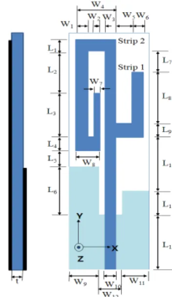
Fig. 1 shows the specific configuration designed for the multiband printed monopole antenna, which consists of two different length strips. The proposed antenna is etched on an inexpensive FR4 substrate with 4.4 relative permittivity and 1.0 mm thickness. The total sizes of the substrate and ground plane of the proposed antenna that was used in this study were 15⨉50 and 15⨉25 mm
2, respectively. A 50Ω microstrip line was used in the antenna design, which served the feeder. The radiating element was placed on the same side as the feeding strip, and the ground plane was placed on the other side of the substrate.
Fig. 1 Configuration of the microstrip‐fed monopole antenna with two hook‐shaped strips, asymmetry ground plane and a rectangular slit in the ground
The proposed antenna had two hook‐shaped
strips and a rectangular slit in the ground plane.
The microstrip line width was 2.0 mm for feeding.
The two hook‐shaped strips {(W
10⨉(L
7+L
8))+ (W
4⨉L
1)+(W
1⨉(L
2+L
3))+(W
8⨉L
4)+(W
7⨉L
3)}and {((W
5+W
6)⨉L
9)+ (W
6⨉(L
8))} were connected to the microstrip line. Two branch strips are attached feed line to form different current paths which make the antenna resonant in WLAN and WiMAX frequency bands.
To obtain the optimal parameters (lines and lengths) of the proposed antenna for WLAN and WiMAX application, HFSS [20], a full‐wave commercial EM software capable of simulating a finite substrate and a finite ground structure, was used. The length and width of the strip line match the input impedance of the WLAN and WiMAX patch antenna.
2.1 Effect of the hook‐shaped strip 2, L
3Figure 2 illustrates the return loss for different values of the hook‐shaped strip 2, L
3. It can be seen from the figure that the impedance bandwidth and characteristics of return loss was not greatly changed when L
3was change from 9.0 mm to 13.0 mm in the 2.4 GHz and 3.5 GHz bands. However, it can be further seen from the figure that the impedance bandwidth and characteristics of return loss was changed in the 5 GHz band. To design a good triple‐band WLAN/WiMAX operation, L
3was set at 11.0 mm.
2.2 Effect of the hook‐shaped strip 1, L
8Figure 3 illustrates the return loss for different values of the hook‐shaped strip 1, L
8. It can be seen from the figure that the impedance bandwidth and characteristics of return loss was not greatly changed when L
8was change from 8.0 mm to 12.0 mm. However, it can be further seen from the figure that the impedance characteristics of return loss was changed in the 5 GHz band. To design a good triple‐band WLAN/WiMAX operation, L
8was set at 10.0 mm.
2.3 Effect of the symmetry ground plane Figure 4 illustrates the return loss for effect of the symmetry ground plane. In the case of symmetry ground plane (L
10was 6 mm and L
11was 11.0 mm), it can be seen from the figure that the impedance bandwidth and characteristics of return loss was so good in the 2.4 and 3.5 GHz bands. However, it can be seen from the figure that the impedance bandwidth and characteristics of return loss was greatly changed and worsen in the 5 GHz band. To design an optimal triple‐band WLAN/WiMAX operation, we need alter the length of the ground plane, L
11. Thus, it is implied that the ground plane is very important parameters in the antenna design, because the string of the bandwidth depends on the ground size [21-23]
2.4 Effect of the rectangular slit length, L
11Figure 5 illustrates the return loss for different values of the rectangular slit length, L
11. It can be seen from the figure that the impedance bandwidth and characteristics of return loss was not changed when L
11increases from 5.0 mm to 9.0 mm in the 2.4 and 3.5 GHz bands. However, according to our expectations, it can be seen from the figure that the impedance bandwidth and characteristics of return loss was greatly changed when L
11was change from 5.0 mm to 9.0 mm in the 5 GHz band.
Thus, it is implied that the length of L11 affected to resonance of 5 GHz band. To design a good triple‐band WLAN/WiMAX operation, L
11was set at 7.0 mm.
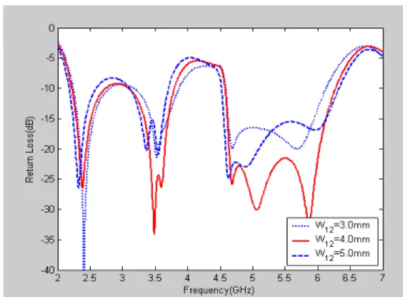
2.5 Effect of the rectangular slit width, W
12Figure 6 illustrates the return loss for different values of the rectangular slit width, W
12. It can be seen from the figure that the impedance bandwidth of return loss was not nearly changed when W
12varied from 3.0 mm to 5.0 mm. However, it can be
further seen from the figure that the characteristics
of impedance bandwidth of the operating bandwidth
were best when W
12was 4.0 mm. To design a good triple‐band WLAN/WiMAX operation, W
12was set at 4.0 mm.
2.6 Effect of the slit in the ground plane To realize the wideband operation of the proposed dual‐band WLAN/WiMAX antenna, a rectangular slit in the ground was introduced into the ground plane to alter the input impedance characteristics. The optimal values of the rectan -gular slit width (W
12) and length (L
11) were determined. To design triple‐band WLAN/WiMAX antenna, W
12was set at 4.0 mm, and L
11was set at 7.0 mm. Figure 7 shows the VSWR with and without a slit in the ground. It was seen from the figure that the resonant frequency is not generated in the 3.5 GHz band and the impedance bandwidth and the characteristics of return loss become worsen. Thus it was implied that the return loss of the proposed antenna heavily depended on the rectangular slit in the ground plane.
Fig. 2 Simulated return loss of the proposed antenna with different values of the hook‐shaped
strip 2, L
3Fig. 3 Simulated return loss of the proposed antenna with different values of the hook‐shaped
strip 1, L
8Fig. 4 Simulated return loss of the proposed antenna with symmetry ground plane
Fig. 5 Simulated return loss of the proposed antenna with different values of the rectangular slit
length, L
11Fig. 6 Simulated return loss of the proposed antenna with different values of the rectangular slit
length, W
12Fig. 7 Simulated return loss of the proposed antenna with and without a rectangular slit
The proposed antenna structure has several design parameters which can handle the resistance and reactance of the antenna input impedance. There- fore, the dimensions of the proposed antenna are set as follows: L
1= 2.0 mm; L
2= 7.0 mm; L
3= 11.0 mm; L
4= 2.0 mm; L
5= 2.0 mm; L
6= 11.0 mm; L
7= 3.0 mm; L
8= 10.0 mm; L
9= 3.0 mm; L
10= 10.0 mm; L
11= 7.0 mm; L
12= 13.0 mm; W
1= 2.0 mm; W
2= 1.0 mm; W
3= 1.0 mm; W
4= 7.0 mm;
W
5= 3.0 mm; W
6= 2.0 mm; W
7= 1.0 mm; W
8= 4.0 mm; W
9= 5.0 mm; W
10= 2.0 mm; W
11= 5.0 mm; W
12= 4.0 mm; h = 1.0 mm. Based on the design dimension, the proposed compact antenna
was constructed and studied. A prototype of the proposed antenna was fabricated with the aforementioned design parameters, and is shown in Figure 8(a) and (b).
(a) (b)
Fig 8. Prototype of the proposed dual band antenna ; (a) front view ; (b) back view
Ⅲ. MEASUREMENT
The proposed antenna was experimentally tested, and the results are presented in this section. The prototype of the proposed antenna was constructed and experimentally analyzed to verify the validity of the suggested method for fabricating dual‐
broadband antennas. Typical proposed antennas were measured using an Anritsu MS4644A vector network analyzer. The far‐field radiation patterns and gains were measured using a far‐field anechoic absorber obtained from EMW Corporation.
Figure 9 shows the measured and simulated impedance bandwidth of the fabricated prototype.
The results demonstrate that both of them meet a
generally acceptable agreement. It is can be seen
from the figure that a little difference exists
between the simulated and measured results, which
may occur because of the effect of the SMA
conductor. Based on the return loss of ‐10dB,
which is acceptable for each application, the
impedance bandwidth of the proposed antenna was
about 1,527 MHz to 1,763 MHz (2.395~3.922 GHz
to 4.337~6.43 GHz). The two wide‐impedance
bandwidths that were obtained cover the operating bandwidths of the WLAN and WiMAX bands.
Clearly, the design prototype of the proposed antenna has sufficient bandwidth to cover the needs of the 2.4 GHz and 5 GHz WLAN bands (2.
4~2.484 GHz and 5.15~5.825 GHz, respectively) and to cover the needs of 3.5GHz and 5GHz WiMAX bands (2.5~2.69, 3.4~3.7, and 5.15~5.35, 5.47‐5.725, and 5.725‐5.825 GHz, respectively).
Fig. 9 Simulated and measured return loss vs. the frequencies of the proposed antenna
Figures 10, 11, and 12 show the measured 2D far‐field radiation patterns of the proposed antenna. Figure 10 (a), (b), and (c) show the 2D radiation pattern at 2.4 GHz, 2.44 GHz, and 2.48 GHz, respectively. The purple line represents the radiation pattern at 2.4 GHz, and the red and green lines represent the radiation patterns at 2.44 and 2.48 GHz, respectively. The 3dB beam width (HPBW) in the x-y plane was 50.60°, and in the x-z plane, 44.66°, at 2.4 GHz. Figure 11 (a), (b), and (c) show the 2D radiation pattern at 3.4 GHz, 3.55 GHz, and 3.7 GHz, respectively. The purple line represents the radiation pattern at 3.3 GHz, and the red and green lines represent the radiation patterns at 3.55 and 3.7 GHz, respectively. The 3dB beam width (HPBW) in the x-z plane was 57.20°, and in the y-z plane, 100.06°, at 3.7 GHz. Figure 12
(a), (b), and (c) show the 2D radiation pattern at 5.1 GHz, 5.3 GHz, 5.7 GHz, and 5.9 GHz, respectively. The purple and red lines represent the radiation patterns at 5.1 and 5.3 GHz, and the green and brown lines, the radiation patterns at 5.7 and 5.9 GHz, respectively. In the case of the 5.3 GHz, the 3dB beam widths (HPBWs) in the x-y and y-z planes were 112.93° and 29.30°, resp- ectively. In the case of the 5.9 GHz, the 3dB beam widths (HPBWs) in the x-y and y-z planes were 103.73° and 36.33°, respectively. It can be seen that the radiation patterns were approximately omni‐
directional in all the operating bands.
(a) (b) (c)
Fig. 10 Radiation patterns of the proposed antenna for wideband operation at 2.4, 2.44, and 2.48 GHz : in the (a) x-z plane ; (b) y-z plane ; and (c) x-y
plane
(a) (b) (c)
Fig. 11 Radiation patterns of the proposed antenna for wideband operation at 3.4, 3.55, and 3.7 GHz : in the (a) x-z plane ; (b) y-z plane; and (c) x-y
plane
(a) (b) (c) Fig. 12 Radiation patterns of the proposed antenna for wideband operation at 5.1, 5.3, 5.7, and 5.9 GHz
: in the (a) x-z plane ; (b) y-z plane ; and (c) x-y plane
Figure 13 (a), (b), and (c) show the 3D measured antenna peak and average gain for frequencies across the 2.4 GHz, 3.5 GHz, and 5 GHz bands. The 2.4 GHz band had an antenna peak gain level of about 5.28~5.62 dBi [Fig. 13(a)], and the 3.5 GHz band, about 4.33~~5.17 dBi [Fig.
13(b)]; and the measured antenna gain levels were about 0.72~1.83 dBi in the 5.2GHz band and about 0.41~0.90 dBi in the 5.8 GHz band [Fig. 13(c)].
The 2.4 GHz band had an antenna average gain level of about 2.38~2.10 dBi [Fig. 13(a)], and the 3.5 GHz band, about 2.38~2.25 dBi [Fig. 13(b)];
and the measured antenna gain levels were about 3.05~1.78 dBi in the 5.2 GHz band and about 4.0 6~3.50 dBi in the 5.8GHz bands [Fig. 13(c)]. The 3D antenna gain had a peak value of 5.62 dBi at 2.48 GHz. At 3.4 GHz, the 3D maximum peak gain was 5.17 dBi; at 5.3 GHz, 1.83 dBi; and at 5.9 GHz, 0.9 dBi. The 3D antenna gain had an average value of 2.10 dBi at 2.48 GHz. At 3.4 GHz, the 3D maximum peak gain was 2.25 dBi; at 5.3 GHz, 1.18 dBi; and at 5.9 GHz,‐3.50 dBi.
(a) (b) (c)
Fig. 13 Measured antenna peak and average gains for the following operating frequencies : (a) 2.4 GHz bands; (b) 3.5 GHz bands; and (c) 5 GHz bands.
Ⅳ. CONCLUSION
A compact planar monopole antenna with triple
band operation for WLAN/WiMAX operations has
been presented. With the two hook‐shaped strips,
asymmetry ground plane and a rectangular slit in
the ground, the proposed antenna can demonstrate
sufficient impedance bandwidth and suitable
radiation characteristics for dual‐band frequency
operation for WLAN/WiMAX applications. Various
parameters of the proposed antenna are optimized
through simulation and prototyped the optimized
geometry. The parametric studies of the proposed
antenna are discussed. Especially, return loss of the
proposed antenna heavily depended on the
rectangular slit in the ground plane. A prototype
capable of generating dual band modes to cover
WLAN/WiMAX systems was tested. This proposed
monopole antenna had ‐10dB impedance bandwidth
of about 1,527 MHz, 1,763 MHz (2.395~3.922 GHz,
4.337~6.43 GHz). The experiment results showed
that good impedance matching was achieved. Good
radiation pattern characteristics for frequencies over
the WLAN/WiMAX bands have also been obtained
for the proposed antenna. The proposed antenna
measured. peak gain varied between 0.41 to 5.62
dBi and average gain varied between ‐4.06 to 1.78
dBi
감사의 글
본 논문은 교육과학기술부와 한국연구재단의 지역혁 신인력양성사업으로 수행된 연구결과임
PREFERENCE
[1] WorldWide Interoperability for microwave acc- ess forum or WiMAX forum, http:www.
wimaxfroum.org.
[2] IEEE 802.16 working group on broadband wireless access standards, U http://grouper.ieee .org/groups/802/16/index.htmlU.
[3] Deploying license‐exempt WiMAX solutions, WiMAX white papers, Intel Corporation, 2005, Uhttp://www.intel.com/netcomma/technologie s/wimax/306013.pdfU.
[4] Understanding Wi‐Fi and WiMAX as metro access solution, U http://www.intel.com/netcomma/ techno logies/wimax/304471.pdfU.
[5] W. S. Chen and Y. H. Yu, “The design of printed rhomb shaped antenna with slits for WiMAX system”, Microwave and Optical Technology Letters, Vol. 49, No. 10, pp.
2503-2508, Oct., 2007.
[6] W. S. Chen and Y. C. Chang, “CPW‐fed printed monopole antenna with branch slits for WiMAX system”, Microwave and Optical Technology Letters, Vol. 50, No. 4, pp.
952-954, April, 2008.
[7] J. H. Lu and B. J. Huang, “Planar multiband monopole antenna with L‐shaped parasitic strip for WiMAX application”, Electronic Letters, Vol. 46, No. 10, pp. 671-67, Oct., 2010.
[8] S. Y. Lee and C. C. Yu, “A novel wideband asymmetric hybrid antenna for WLAN/
WiMAX applications”, Microwave and Optical Technology Letters, Vol. 51, No. 4, pp.
1055-1057, April, 2009.
[9] J. F. Huang and S. H. Wu, “Planar T‐shaped monopole antenna for WLAN/WiMAX app- lication”, IEICE Transactions on Electronics, Vol. 91-C, No. 4, pp. 625-630, April, 2008.
[10] K. G. Thomas and M. Sreenivasan, “A novel triple band printed antenna for WLAN/
WiMAX applications”, Microwave and Optical Technology Letters, Vol. 51, No. 10, pp.
2481-2484, Oct. 2009.
[11] Z. Y. Zhang, G. A. Fu, and S. O. Zuo, “A compact printed monopole antenna for WLAN and WiMAX applications”, Microwave and Optical Technology Letters, Vol. 52, No. 4, pp.
857-861, April 2010.
[12] S. O. Zuo, Y. Z. Yin, and Z. Y. Zhang, “A coupling‐fed multiband antenna for WLAN/
WiMAX applications”, Microwave and Optical Technology Letters, Vol. 52, No. 6, pp.
1283-1286, Jun., 2010.
[13] C. H. Ku, K. K. Li, and W. L. Mao,
“Compact monopole antenna with branch strips for WLAN/WiMAX operation”, Micro- wave and Optical Technology Letters, Vol 52, No. 8, pp. 1858-1861, Aug., 2010.
[14] S. Y. Lin and B. J. Ke, “Dual band rejected microstrip antenna for WLAN/WiMAX app- lications”, Microwave and Optical Technology Letters, Vol 52, No. 8, pp. 1901-1905, Aug., 2010.
[15] K. K. Chen and J. X. Zhao, “Band notched design of the planar monopole antenna for WLAN/WIMAX applications”, Microwave and Optical Technology Letters, Vol 52, No. 12, pp. 2783-2786, Dec., 2010.
[16] H. Nouri, J. Nourinia and Ch. Ghobadi,
“Multiband printed dipole antenna with log‐
periodic toothed structure for WLAN/WIMAX applications”, Microwave and Optical Technology Letters, Vol. 53, No. 3, pp.
536-539, Mar., 2011.
[17] D. B. Lin, I. T. Tang, and Y. J. Wei,
“Compact dual band notched CPW‐fed wide slot antenna for WLAN and WiMAX app- lications”, Microwave and Optical Technology Letters, Vol 53, No. 7, pp. 1496-150, July, 2011.
[18] X. Ren, Y. Yin and S. Zheng, “Wideband rectangular ring patch antenna with a three pointed star strip for WLAN/WiMAX applications”, Microwave and Optical Tech- nology Letters, Vol 53, No. 7, pp. 1677-1680, July 2011.
[19] C. Wang, P. Xu, B. Li and Z. H. Yan, “A
compact multiband antenna for WLAN and
WiMAX applications”, Microwave and Optical
Technology Letters, Vol 53, No. 9, pp.
2016-2018, Sep., 2011.
[20] 구융서, 윤중한, “무선랜과 와이맥스 시스템에 적용가능한 브랜치 라인과 사각 슬릿 접지를 갖 는 모노폴 안테나 설계와 제작”, 한국전자통신 학회 논문지, Vol. 6, No. 5, pp. 611-620, Oct., 2011.
[21] Ansoft High Frequency Structure Simulator (HFSS) Version 10.0, Ansoft Corporation, 2005.
[22] M. J. Ammann and M. John, “Optimum design of the printed strip monopole”, IEEE Antenna and Propagation Magazine, Vol. 47, No. 6, pp. 59-61, Jun., 2005.
[23] M. John and M. J. Ammann, “Optimisation of impedance bandwidth for the printed rec- tangular monopole antenna”, Microwave and Optical Technology Letters, Vol. 47, No. 2, pp.
153-154, Feb., 2007.
저자 소개
윤중한(Joong-Han Yoon)
1994년 2월 인하대학교 전자공학과 졸 업(공학사)
1996년 8월 인하대학교 대학원 전자공 학과 졸업(공학석사)
2003년 2월 인하대학교 대학원 전자공학과 졸업(공학박사) 2005년 8월 인하대학교 Post-Doc.
2006년 11월 요코하마 국립대학 Post-Doc.
2008년 8월 삼성전기 책임연구원 현재 신라대학교 전자공학과 조교수
※ 관심분야 : RF & Antenna, RFID, Radar
장연길(Yeon-Gil Jang)
2010년 경남대학교 정보통신공학과 졸 업 (공학사)
2011년∼현재 경남대학교 대학원 정보 통신공학과 석사과정
2000년∼현재 에이트론(주) 부장
※ 관심분야 : 능동소자 설계 및 응용, 레이다
이영철(Young-Chul Rhee)