* 국방기술품질원 책임연구원([email protected])
** 교신저자 : 신라대학교([email protected])
접수일자 : 2011. 08. 30 심사(수정)일자 : 2011. 09. 19 게재확정일자 : 2011. 10. 12
무선랜과 와이맥스 시스템에 적용 가능한 브랜치 라인과 사각 슬릿 접지를 갖는 모노폴 안테나 설계와
제작
구융서*․윤중한**
Design and Fabrication of Monopole Antenna with Three Branch Strips and Rectangular Slit Ground for WLAN/WiMAX Applications
Yung-Seo Koo*․Joong-Han Yoon**
요 약
본 논문은 WLAN/WiMAX 시스템에 적용 가능한 평면형 모노폴 안테나를 개발하였다. 제안된 안테나는 3 개의 선로, 비대칭 접지면 그리고 접지면에 사각 슬릿을 가지며 WLAN 대역과 WiMAX 대역을 모두 포함하 도록 설계하였다. 광대역 특성을 갖도록 선로 급전을 사용하였으며 RF-4 기판위에 제작되었다. 얻어진 시뮬 레이션 결과는 실험결과와 잘 일치되었으며 VSWR 1 : 2을 기준으로 낮은 대역에서는 9.95%, 높은 대역에서 는 76.05%의 임피던스 대역폭을 얻었다. 이러한 결과는 WLAN/WiMAX 시스템에서 요구하는 특성을 잘 만 족시킨다. 또한 2D 그리고 3D 방사패턴과 이득에 측정결과가 제시되고 논의되었다.
ABSTRACT
A planar monopole antenna that was developed for WLAN/WiMAX application is presented in this paper. The proposed antenna with three strips, an asymmetrical ground plane, and a rectangular slit in the ground is designed to cover the popular frequency spectrum of WLAN (wireless local area network) bands and WiMAX (Worldwide Interoperability for Microwave Access) bands. The proposed antenna, which is capable of wideband operation, is fed by a strip line and fabricated on an FR-4 substrate.
The obtained numerical results agree well with the experiment data. It was validated that the configuration can meet the demands for the WLAN/WiMAX systems and effectively enhanced the impedance bandwidth to 9.95% for the lower band and 76.05% for the upper band for VSWR < 1 : 2. This paper also presents and discusses the 2D radiation patterns and 3D gains according to the results of the experiment.
키워드
WLAN/WiMAX antenna, monopole antenna, asymmetry ground plane, rectangular slit WLAN/WiMAX 안테나, 모노폴 안테나, 비대칭 접지면, 사각 슬릿
Ⅰ. INTRODUCTION
The demand for low-profile, lightweight, and low-cost broadband antennas has increased with the widespread deployment of short-distance wireless communications. The wireless local area network (WLAN) is one of the most popular communication systems that operate in the 2.4GHz and 5GHz bands. Since 1999, the WLAN standards, including IEEE 802.11a/b/g systems, were established by IEEE 802.11 Group a. WLAN 802.11b is one of the WLANs, with frequency bands that range from 2.4 to 2.484 GHz for the ISM band.
Also, HIPERLAN 2 was developed for the fre- quency band ranges of 5.15-5.35 GHz, 5.470-5.725 GHz, and 5.725-5.925 GHz. The required frequency for 5GHz WLANs is 5.15-5.35 GHz / 5.725-5.825 GHz for IEEE 802.11a. U-NII covers the frequency band of 5.725-5.825 GHz.
Also, broadband wireless access, commonly known as WiMAX (Worldwide Interoperability for Microwave Access), which is allocated the 2.5-2.69 / 3.4-3.69 / 5.25-5.85GHz bands, is an emerging wireless communication system that can provide broadband access with large-scale coverage. The technology can reach a theoretical 30-mile coverage radius, data rates of up to 75 Mbps, and a throughtput that is close to the 1.5Mbps performance [1-2].
Wireless local area network (WLAN) and worldwide interoperability for microwave access (WiMAX) are currently two of the most popular areas of interest. Therefore, the need for antennas that are capable of operating in the aforementioned frequency bands has led to active research and design of a triple-band-radiating element. Thus, antennas for this prospective dual-mode WLAN/
WiMAX operation are arousing much interest.
To achieve the purpose of using multiband and broadband antennas for WLAN/WiMAX application, much research has been reported in literature
[3-18]. The currently popular antenna designs satisfy WLAN/WiMAX standards via several main methods, as follows. The monopole antenna dominates the dual-band WLAN/WiMAX antenna field [3-10], as do the coplanar waveguide (CPW)-fed [11-14], PIFA [15], and dipole [16] that are used in different areas.
In this research, a monopole antenna with three branch strips for dual bands—i.e., suited to operate in both WLAN band (2.4-2.484, 5.15-5.35, and 5.75-5.85GHz) and WiMAX band (3.4-3.7, 5.15-5.35, 5.47-5.725, and 5.725-5.825GHz) applications—was designed. The optimum impedance matching for this proposed configuration was achieved by adjusting the length and width of the three branch strips, the asymmetry ground plane, and the rectangular slit in the ground. The proposed antenna structure has several design parameters that can handle the resistance and reactance of the antenna input impedance. It offers enough bandwidth for dual- band WLAN/WiMAX services. The details of the proposed antenna design and the experiment results are presented and discussed next.
Ⅱ. ANTENNA DESIGN
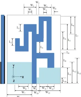
The geometry of the proposed monopole antenna with three branch strips is shown in Figure 1. The total size of the proposed antenna is 37 mm x 40 mm. As shown in the figure, the antenna consists of three branch strips, an asymmetry ground plane, and a rectangular slit in the ground plane. The antenna was mainly constructed with three branch strips and fed by a microstrip line. The three branch strips were printed on an inexpensive FR4 substrate with a relative permittivity of 4.4 and a thickness of 1.0 mm. By properly calculating and carefully arranging the radiating bended strips, the capacitive and inductive effects of electromagnetic coupling were compensated for. The ground size of
the proposed antenna is 37 mm Χ 15 mm. The ground plane is asymmetrical at the base line of the feeding strip line.
Fig. 1 Configuration of the microstrip-fed monopole antenna with three strips and a rectangular slit in
the ground.
Also, a rectangular slit in the ground is introduced to obtain a WLAN/WiMAX suitable operating bandwidth. The rectangular slit in the ground is positioned on the other side, at the three strips and on the feeding strip line. The width and length of the rectangular slit in the ground were selected for wide-impedance-bandwidth WLAN/ WiMAX operation. Thus, the impedance bandwidth for the desired frequency bands can be easily achieved. To obtain the optimal parameters (lines, lengths, and gaps) of the proposed antenna for WLAN/WiMAX application, HFSS [17], a full-wave commercial EM software that can simulate a finite substrate and a finite ground structure, was used. The length and width of the strip line match the input impedance of the WLAN/WiMAX patch antenna.
2.1 Effect of the left branch strip, L2
The length, L2, is a very important parameter in the design of the proposed antenna because of the strong dependence of the bandwidth on lower- frequency bands. Figure 2 illustrates the return loss for different values of the left branch strip, L2. It can be seen from the figure that the suitable bandwidth of the lower-frequency band was obtained when L2 was 4.0 mm.
Fig. 2 Simulated return loss of the proposed antenna with different values of the upper branch
strip, L2.
2.2 Effect of the gap between the upper branch strip and the bottom branch strip, L3
Figure 3 illustrates the return loss for different gaps (L3) between the upper branch strip and the bottom branch strip, L3. It can be seen from the figure that the suitable bandwidth of the lower-frequency band was obtained when L3 was 6.0 mm in the lower-frequency bands. Also, in the higher-frequency band, the characteristics and ban- dwidth of the return loss became better and wider than those of the other cases (when L3 was 5.0 mm and 7.0 mm). To design a good dual-band WLAN/WiMAX operation, L3 was set at 6.0 mm.
2.3 Effect of the upper-right branch strip, L7
Figure 4 illustrates the return loss for different values of the upper right branch strip, L7. It can be
seen from the figure that the impedance bandwidth of the lower-frequency band depended on the upper right branch strip, L7. It can be further seen from the figure that the impedance bandwidth of the lower-frequency band become narrow when L7
increased at 17.5 mm. The impedance bandwidth of the higher-frequency bands did not significantly change in the desired frequency bands. L7 was set at 16.5 mm.
Fig. 3 Simulated return loss of the proposed antenna with different gaps between the upper
branch strip and the bottom branch strip, L3.
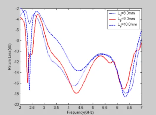
2.4 Effect of the bottom right branch strip, L9
Figure 5 illustrates the return loss for the different values of the bottom right branch strip length, L9.
Fig. 4 Simulated return loss of the proposed antenna with different values of the upper right
branch strip, L7.
The impedance bandwidth of the lower-frequency and higher-frequency bands worsened and widened when L9 was 8.0 mm. Also, the impedance bandwidth of the lower-frequency and higher- frequency bands became narrower when L9 was 10.0 mm. To design a good dual-band WLAN/
WiMAX operation, L9 was set at 9.0 mm.
Fig. 5 Simulated return loss of the proposed antenna with different values of the bottom right
branch strip, L9.
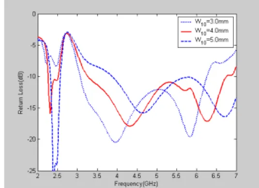
2.5 Effect of the slit in the ground plane
To realize the wideband operation of the proposed dual-band WLAN/WiMAX antenna, a rectangular slit in the ground was introduced into the ground plane to alter the input impedance characteristics. Figure 6 shows the return loss for different values of the slit width, W10. It can be seen from the figure that the impedance bandwidth of the lower-frequency and higher-frequency bands worsened and widened when W10 was 3.0 mm. It can be further seen from the figure that the impedance bandwidth of the lower-frequency and higher-frequency bands became narrower when W10 was 5.0 mm.
Figure 7 shows the return loss for different values of the rectangular slit length, L10. It can be seen from the figure that the impedance bandwidth of the lower-frequency and higher-frequency bands became narrower when L10 was 3.0 mm. It can be
further seen from the figure that the impedance bandwidth of the lower-frequency and higher- frequency bands worsened and widened when L10
was 5.0 mm. The optimal values of the rectangular slit width (W10) and length (L10) were determined.
To design a dual-band WLAN/WiMAX antenna, W10
was set at 4.0 mm, and L10 was set at 4.0 mm.
Fig. 6 Simulated return loss of the proposed antenna with different values of the slit width, W10.
Figure 8 shows the return loss with and without a slit in the ground. It was found that the return loss of the proposed antenna heavily depended on the rectangular slit in the ground plane. The ground plane dimensions are thus very important
Fig. 7 Simulated return loss of the proposed antenna with different values of the slit length, L10.
parameters in the ant1enna design, because the string of the bandwidth depends on the ground size [18-20]. Certainly, with the variation of the width and length in the rectangular slit, the return loss can be controlled at less than -10 dB, thus covering the frequency bandwidth for WLAN (2.4-2.484, 5.15-5.35, and 5.75-5.85 GHz) and WiMAX (3.4-3.7, 5.15-5.35, 5.47-5.725, and 5.725- 5.825 GHz).
Fig. 8 Simulated return loss of the proposed antenna with and without a rectangular slit in the
ground.
Therefore, the proposed antenna design can provide a wide bandwidth while retaining stable performance via the optimized geometrical para- meters. The dimensions of the proposed antenna were set as follows: L1 = 3.0 mm L2 = 4.0 mm; L3
= 6.0 mm; L4 = 7.5 mm; L5 = 12.5 mm L6 = 9.0 mm; L7 = 16.5 mm; L8 = 1.5 mm L9 = 9.0 mm; L10
= 4.0 mm; L11 = 12.0 mm; L12 = 15.0 mm; L13 = 18.0 mm; W1 = 2.0 mm W2 = 6.0 mm; W3 = 1.0 mm; W4 = 6.0 mm; W5 = 1.0 mm W6 = 6.0 mm;
W7 = 8.0 mm; W8 = 17.0 mm W9 = 2.0 mm W10 = 4.0 mm; W11 = 5.0 mm; W12 = 3.0 mm; and W13 = 16.0 mm.
Fig. 9 Fabrication of the proposed antenna : (a) front view and (b) back view.
The proposed antenna was constructed and experimentally tested, and the measured results are given in this paper. A prototype of the proposed dual-band antenna was fabricated with the aforementioned design result, and is shown in Figure 9 (a) and (b).
Ⅲ. FABRICATION & MEASUREMENT
A proposed antenna was implemented, and the frequency response of the input return loss of the proposed antenna was measured with an Agilent Technologies E8362B network analyzer from Kyungnam University. The far-field radiation patterns and gains were measured with the far-field anechoic absorber from EMW Corporation. Figure 10 shows the measured and simulated VSWR for the fabricated antenna. The measured data generally agree with the simulated results. Although good agreement can be seen, however, there are small discrepancies between the simulated and measured results, which may have occurred because of the effect of the SMA conductor and the fabrication imperfections. The proposed antenna can generate three separate resonant modes at about 2.46 GHz, 4.4 GHz, and 6.52 GHz to cover 2.4, 5.2, and 5.8 GHz, respectively, with good impedance matching conditions. Based on the VSWR of 1:2.0, which is acceptable for each application, the impedance bandwidth of the proposed antenna was about 245 MHz to 3,945 MHz (2.34-2.585 GHz to 3.215-7.16
GHz). The two wide-impedance bandwidths that were obtained cover the operating bandwidths of the WLAN and WiMAX bands. Clearly, the design prototype of the proposed antenna has sufficient bandwidth to cover the needs of the 2.4GHz and 5GHz WLAN bands (2.4-2.484 GHz and 5.15-5.825 GHz, respectively) and to cover the needs of the 3.5GHz and 5GHz WiMAX bands (3.4-3.7, and 5.15-5.35, 5.47-5.725, and 5.725-5.825 GHz, respectively).
Fig. 10 Simulated and measured VSWR vs. the frequencies of the proposed antenna.
To further investigate the physical effects of the added strip to the produced resonant modes, the excited surface current distribution that was obtained from the HFSS simulation on the proposed antenna, including the microstrip-fed monopole and the radiating bended strips at the resonance frequencies of 2.3, 4.3, and 6.3 GHz, were analyzed and are shown in Figure 11 (a), (b), and (c), respectively. As expected, for the lowest band excitation, a larger surface current density was observed along the left branch strip and the bottom right branch strip. This implies that the left and bottom right branch strips are the major radiation elements for the proposed antenna at the first operating bands. Also, in the second band excitation, a larger surface current density was ob- served along the left branch strip. This implies that
the left branch strip is the major radiation element for the proposed antenna at the second operating bands. For the highest band excitation, a larger surface current density was observed along the bottom right branch strip of the shortest strip. It seems that the bottom right branch strip cont- ributes to the radiation at the highest operating band. As with the current density, the length of L3 and L7 greatly affect the lower frequency bands.
(a) f = 2.3 GHz (b) f = 4.3 GHz (c) f = 6.3 GHz Fig. 11 Simulated results of the surface current of the proposed antenna: (a) f = 2.3 GHz (b) f = 4.3
GHz and (c) f = 6.3 GHz.
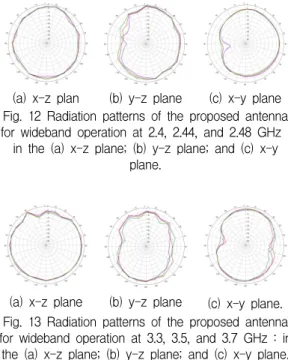
Figures 12, 13, and 14 show the measured 2D far-field radiation patterns of the proposed antenna.
Figure 12 (a), (b), and (c) show the 2D radiation pattern at 2.4 GHz, 2.44 GHz, and 2.48 GHz, respectively. The blue line represents the radiation pattern at 2.4 GHz, and the red and green lines represent the radiation patterns at 2.44 and 2.48 GHz, respectively. The 3dB beam width (HPBW) in the x-z plane was 137.86°, and in the y-z plane, 153.66°, at 2.44 GHz. Figure 13 (a), (b), and (c) show the 2D radiation pattern at 3.3 GHz, 3.5 GHz, and 3.7 GHz, respectively. The blue line represents the radiation pattern at 3.3 GHz, and the red and green lines represent the radiation patterns at 3.5 and 3.7 GHz, respectively. The 3dB beam width (HPBW) in the x-z plane was 26.33°, and in the y-z plane, 28.10°, at 3.5 GHz. Figure 14 (a), (b), and (c) show the 2D radiation pattern at 5.1 GHz,
5.3 GHz, 5.6 GHz, and 5.9 GHz, respectively. The blue and red lines represent the radiation patterns at 5.1and 5.3 GHz, and the green and black lines, the radiation patterns at 5.6 and 5.9 GHz, respectively. In the case of the 5.3GHz band, the 3dB beam widths (HPBWs) in the x-y and x-z planes were 82.88° and 108.38°, respectively. In the case of the 5.6GHz band, the 3dB beam widths (HPBWs) in the x-y and y-z planes were 81.18°
and 69.7°, respectively. It can be seen that the radiation patterns were approximately omni- dire- ctional in all the operating bands.
(a) x-z plan (b) y-z plane (c) x-y plane Fig. 12 Radiation patterns of the proposed antenna for wideband operation at 2.4, 2.44, and 2.48 GHz : in the (a) x-z plane; (b) y-z plane; and (c) x-y
plane.
(a) x-z plane (b) y-z plane (c) x-y plane.
Fig. 13 Radiation patterns of the proposed antenna for wideband operation at 3.3, 3.5, and 3.7 GHz : in
the (a) x-z plane; (b) y-z plane; and (c) x-y plane.
(a) x-z plane (b) y-z plane (c) x-y plane Fig. 14 Radiation patterns of the proposed antenna
for wideband operation at 5.1, 5.3, 5.6, and 5.9 GHz: in the (a) x-z plane; (b) y-z plane; and (c)
x-y plane.
Figure 15 (a), (b), and (c) show the 3D measured antenna peak and average gain for frequencies across the 2.4GHz, 3.5GHz, and 5GHz bands. The 2.4GHz band had an antenna peak gain level of about -0.39̴~4.68 dBi [Fig. 15 (a)], and the 3.5GHz band, about 0.701~4.467 dBi [Fig. 15 (b)]
and the measured antenna gain levels were about 0.523~2.884 dBi in the 5.2GHz band and about -0.557~1.221 dBi in the 5.8GHz band [Fig. 15 (c)].
The 2.4GHz band had an antenna average gain level of about -4.987~-0.550 dBi [Fig. 15 (a)], and the 3.5GHz band, about -5.002~-0.247 dBi [Fig. 15 (b)] and the measured antenna gain levels were about -4.202~0.525dBi in the 5.2GHz band and about -1.816~-6.088 dBi in the 5.8GHz bands [Fig.
15 (c)]. The 3D antenna gain had a peak value of 4.682 dBi at 2.48 GHz. At 3.5 GHz, the 3D maximum peak gain was 4.545 dBi at 5.3 GHz, 2.884 dBi and at 5.9 GHz, 1.303 dBi.
Ⅵ. CONCLUSION
A novel three-branch-strip monopole antenna for WLAN/WiMAX application was constructed and successfully implemented. The designed antenna consists of three strips, an asymmetrical ground plane, and a rectangular slit in the ground, and was designed for dual-band WLAN/WiMAX application.
The three-strip design showed good impedance bandwidth matching of less than 1:2 VSWR and achieved over the WLAN/WiMAX bands. It can generate three resonance values centered at about 2.4, 3.7, and 5.5 GHz to cover the 2.4/5.2/5.8GHz WLAN bands and the 3.5/5.5GHz WiMAX bands.
Various parameters of the proposed antenna were optimized through a simulation, and the optimized geometry was prototyped. A prototype that was capable of generating two wide resonant modes to cover WLAN/WiMAX systems was tested. This proposed antenna had an impedance bandwidth
(VSWR, 1:2) of about 245 MHz and 3,945 MHz (2,340-2,585 MHz and 3,215-7,160 MHz, respectively), or about 9.95% and 76.05%, respectively. The proposed antenna has nearly omni-directional radiation characteristics and a moderate gain over the operating bands. Also, the measured peak gain of the proposed antenna varied from -0.557 to 5.952 dBi.
(a) 2.4GHz bands
(b) 3.5GHz bands
5GHz bands
Fig. 15 Measured antenna peak and average gains for the following operating frequencies : (a) 2.4GHz
bands (b) 3.5GHz bands and (c) 5GHz bands.
REFERENCE
[1] Deploying License Exempt WiMAX Solution Intel Santa Clara CA, 2005. [Online] Available http://www.intel.com/netcomms/technologies/
wimax.
[2] WorldWide Interoperability for microwave access forum or WiMAX forum,
http://www.wimaxfroum.org.
[3] S. Y. Lee and C. C. Yu, "A novel wideband asymmetric hybrid antenna for WLAN/
WiMAX applications", Microwave Optical Tec- hnology Letters Vol. 51, No.4, pp. 1055-1057, 2009.
[4] J. F. Huang and S. H. Wu, "Planar T-shaped monopole antenna for WLAN/WiMAX appli- cation", IEICE Trans Electronics, Vol. 91, No.
4, pp. 625-630, 2008.
[5] K. G. Thomas and M. Sreenivasan, "A novel triple band printed antenna for WLAN/
WiMAX applications", Microwave Optical Technology Letters, Vol. 51, No. 10, pp.
2481-2484, 2009.
[6] Z. Y. Zhang, G. A. Fu, and S. O. Zuo, "A compact printed monopole antenna for WLAN and WiMAX applications", Microwave Optical Technology Letters, Vol. 52, No. 4, pp.
857-861, 2010.
[7] S. O. Zuo, Y. Z. Yin, and Z. Y. Zhang, "A coupling-fed multiband antenna for WLAN/
WiMAX applications", Microwave Optical Tec- hnology Letters, Vol. 52, No. 6, pp. 1283-1286, 2010.
[8] C. H. Ku, K. K. Li, and W. L. Mao, "Compact monopole antenna with branch strips for WLAN/WiMAX operation", Microwave Opt Technol Lett 52, pp. 1858-1861, 2010.
[9] S. Y. Lin and B. J. Ke, "Dual band rejected microstrip antenna for WLAN/WiMAX appl- ications", Microwave Optical Technology Le- tters, Vol. 52, pp. 1901-1905, 2010.
[10] K. K. Chen and J. X. Zhao, "Band notched design of the planar monopole antenna for WLAN/WIMAX applications", Microwave Optical Technology Letters, Vol. 52, No. 12, pp. 2783-2786, 2010.
[11] H. W. Li and C. H. Ku, "Novel planar triple band monopole antenna for WLAN/WiMAX
application", Microwave Optical Technology Letters, Vol. 52, No. 11, pp. 2405-2408, 2010.
[12] W. S. Chen and Y. H. Yu, "Compact design of T-type monopole antenna with asym- metrical ground plane for WLAN/WiMAX applications", Microwave Optical Technology Letters, Vol. 52, No. 2, pp. 515-519, 2008.
[13] Q. Y. Zhang and Q. X. Chu, "Triple band dual rectangular ring printed monopole antenna for WLAN/WiMAX application", Microwave Optical Technology Letters, Vol.
51, No. 12, pp. 2845-2848, 2009.
[14] L. H. Ye and Q. X. Chu, "Compact dual wideband antenna for WLAN/WiMAX appli- cation", Microwave Optical Technology Letters, Vol. 52, No. 6, pp. 1228-1231, 2010.
[15] S. O. Zuo, Y. Z. Yin, Z. Y. Zhang, and W. J.
Wu, "A compact triple band antenna for WLAN and WiMAX applications", Microwave Optical Technology Letters, Vol. 52, No. 5, pp.
919-922, 2010.
[16] Q. Y. Zhang, Q. X. Chu, and Z. H. Tu,
"Triple band compact printed dipole antenna with wideband integrated balun for WLAN/
WiMAX applications", Microwave Optical Technology Letters, Vol. 52, No. 7, pp.
1619-1622, 2010.
[17] High Frequency Structure Simulator (HFSS) Version 10.0, Ansoft Corporation, 2005.
[18] M. J. Ammann and M. John, "Optimum design of the printed strip monopole", IEEE Antenna Propagation Magazine, Vol. 47, No.
6, pp. 59-61, 2005.
[19] J. Liang, L. Guo, C. C. Chiau, X. Chen and C.
G. Parini, "Study of CPW-fed circular disc monopole antenna for ultra wideband appl- ications", IEE Proc Microwave Antenna Propagation, Vol. 152, No. 6, pp. 520-526, 2005.
[20] M. John and M. J. Ammann, "Optimization of impedance bandwidth for the printed rec- tangular monopole antenna", Microwave Op- tical TechNology Letters, Vol. 47, No. 2, pp.
153-154, 2005.
저자소개
구융서(Ryung-Seo Koo)
1989년 국방기술품질원 입사 2010년 경남대학교 전파공학과 졸 업(공학석사)
2011년 경남대학교 IT융합 박사과 정 재학 중
현재 국방기술품질원 방공유도무기체계 연구원
※ 관심분야 : RF, Radar System Integration
윤중한(Joong-Han Yoon)
1992년 인하대학교 전자공학과 졸 업(공학사)
1994년 인하대학교 대학원 전자공 학과 졸업(공학석사)
2003년 인하대학교 대학원 전자공학과 졸업(공학 박사)
2005년 8월 인하대학교 Post-Doc.
2006년 11월 요코하마 국립대학 Post-Doc.
2008년 8월 삼성전기 책임연구원 현재 신라대학교 전자공학과 조교수
※ 관심분야 : RF & Antenna, RFID, Radar