한국표면공학회지 J. Korean Inst. Surf. Eng.
Vol. 50, No. 5, 2017.
https://doi.org/10.5695/JKISE.2017.50.5.421
<연구논문>
ISSN 1225-8024(Print) ISSN 2288-8403(Online)
Unipolar pulse를 이용하여 형성된 Al6061 합금 표면의 MAO 코팅의 표면 구조에 대한 연구
김남열a, 박승호b, 박기용a, 최진섭a,*
a인하대학교 화학공학과, b㈜포인트엔지니어링
Surface Morphological Properties of Micro-arc Oxidation Coating on Al6061 Alloys using Unipolar Pulse
Nam-youl Kima, Seung-Ho Parkb, Ki-Youg Parka, and Jin-Sub Choia,*
a
Department of Chemistry and Chemical Engineering, Inha Univeristy, Incheon, 22212, Korea
b
Point engineering CO.,LTD, Chungcheongnam-do, 31409, Korea
(Received September 15, 2017 ; revised October 11, 2017 ; accepted October 11, 2017)
Abstract
Herein, we investigated surface morphological characteristics of anodic films on Al6061 alloy prepared by unipolar pulsed Micro-arc oxidation (MAO) in a mixed solution of Na
2SiO
3+ KOH. The number and size of pores as well as craters on anodic alumina surface were studied as a function of different voltages, duty cycles and applied anodic current densities. The morphological characteristics of all samples were inves- tigated by scanning electron microscopy, conforming that the most uniform surface morphology of MAO films on Al1050 alloy was obtained at high applied current density with low duty cycle.
Keywords : Micro-arc oxidation, Aluminum, Surface, Uniformity
1. 서 론
Micro-arc oxidation (이하 MAO) 코팅법은 Plasma electrolytic oxidation (PEO) 라고도 알려져 있으며 알루미늄, 타이타늄, 마그네슘 등의 밸브 메탈(valve metal) 표면에 전기화학적 플라즈마 방전을 일으켜 두꺼운 금속산화물을 친환경적으로 코팅할 수 있는 방법이다[1-3].
MAO 코팅법은 기존의 양극산화 방법과 유사한 방법으로 진행되나 일반적인 양극산화와 다르게 더 높은 전압을 인가하여 두껍고 치밀한 산화피막을 빠른 시간안에 형성할 수 있고[4,5], 이렇게 형성된
MAO 코팅층은 내부식성, 기계적 경도, 내열성, 기 판과의 부착성이 뛰어나다는 장점이 있다[6,7]. MAO 코팅층은 전해질의 조성, 전류인가방법(교류, 직류 또 는 펄스직류), 인가전류밀도, 인가시간 등의 조건에 따라 그 특성이 결정되는데[8-11], 최근 연구동향은 전해질의 조성에 따라 표면 특성을 변화시키거나 [12] 플루오린을 첨가하여 내부식성, 내마모성을 증 가시키는 연구[13,14], 균일한 표면의 코팅층을 형 성하여 다양한 색을 입히는 연구[15,16]등이 있으나, 밸브 메탈 을 주로 이용하는 산업에서 기계적 특성 향상을 위한 코팅층의 표면형태, 두께 및 강도에 대 한 연구가 주를 이루고 있다[17-22]. 일반적으로 펄 스형태의 전류 및 전압을 인가하면, 주파수를 조절 하여 금속과 전해질 계면의 플라즈마를 제어할 수 있는데[23], 전기적 조건(electrical parameter)를 조 절하는 방법에 따라 코팅층의 공극률(porosity) 및
*Corresponding Author: Jinsub Choi
Department of Chemistry and Chemical Engineering, Inha Univeristy
Tel: +82-32-860-7476 ; Fax: +82-32-872-4046
E-mail: [email protected]
422 김남열 외/한국표면공학회 50 (2017) 421-426
물성을 변화시킬 수 있기 때문에 생활성 물질[24], 촉매로의 적용도 가능하며[25], 코팅층의 밀도를 증 가시켜 우수한 기계적 특성을 나타낼 수 있는 것으 로 알려져 있다. 그러나, MAO 코팅은 기본적으로 플라즈마 방전에 의한 산화층의 생성을 기반으로 하기 때문에, 높은 전압에 의한 순간적인 아크(arc) 발생으로 인한 기공(pore) 생성 및 균열의 생성이 불가피하고, 이러한 틈으로 불순물 등이 침투할 우 려가 있기 때문에 제품의 순도가 매우 중요한 diffuser 나 CVD 장비에서는 아직까지 적용이 어려 우며, 아크 발생을 제어하여 더욱 균일하고 치밀한 구조의 산화층을 형성하는 연구가 계속 부각되고 있다. 따라서, 본 연구에서는 보다 균일도가 높은 산화층을 생성하기 위해 실리케이트 기반 전해질에 서 unipolar pulse를 이용하여 인가전류밀도와 인가 시간에 따른 MAO 코팅층의 형태학적 측면을 분석 하였다.
2. 실험방법
실험에서 사용된 시편은 Al6061 규격의 두께 3 mm의 15 mm × 15 mm 크기로 자른 것을 사용하 였다. 실험에서 사용된 전해질은 0.17 M 의 Na2SiO3, 0.67 M 의 KOH 를 증류수에 녹여 사용하였다.
MAO 코팅은 시편인 Al6061을 양극으로, Pt mesh를 음극으로 하여 직류전원장치(Agilent Technology)를 사용하여 진행하였다. 먼저 정전압, 정전류 코팅의 표면 특성을 확인하기 위하여 정전압 실험에서는 1
분동안 각각 220 V, 260 V, 300 V 의 전압을, 정전류 실험에서는 0,16, 0.20, 0.24 A/cm2의 전류밀도를 인 가하여 MAO 코팅을 하였다. 이후, duty cycle을 20% (pulse on time: 0.8초, pulse off time :3.2초) 로 고정 한 후, 인가전류밀도를 각각 0.08, 0.12, 0.16 A/cm2 로 하여 전체 코팅시간을 10분, 30분, 1시간에 걸쳐서 MAO를 하였고, duty cycle 에 따 른 표면 균일도를 확인하기 위해 duty cycle 80%
(pulse on time: 3.2초, pulse off time :0.8초) 로 하 여 실험을 진행하였다. 이후 주사전자현미경 (Hitach, S4300)을 통해 전류밀도와 코팅시간에 따른 MAO 필름의 형태학적 분석을 진행하였다.
3. 결 과
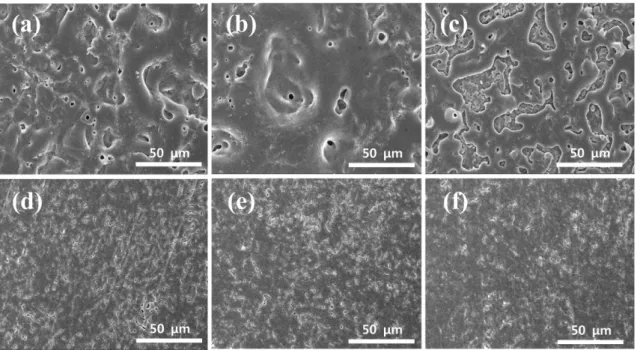
그림 1은 1분동안 각각 정전압, 정전류 방법으로 MAO 코팅을 한 시편의 표면을 주사전자현미경으 로 관찰한 것이다. 먼저 정전압 방법 (a)~(c)와 정 전류 방법 (d)~(f)를 비교하였을 때, 정전류 방법에 서 약 0.8 µm의 크기를 가지는 상대적으로 작은 기 공이 생성되었으며 전체적으로 균일한 코팅이 되었 음을 확인할 수 있었다. 전류밀도를 일정하게 하여 코팅을 하면 산화층이 점진적으로 생성되어 저항이 높아지고, 이에 따라 전압도 상승하게 된다. 전압이 점점 증가하여 임계전압에 도달하면 아크가 발생되 는데, 초기 발생한 아크는 그 세기가 매우 작으며 전체적으로 균일하게 발생된다. 시간이 지남에 따 라 전압이 정상상태에 도달하면 비교적 큰 아크가
Fig. 1. SEM images of MAO coated Al6061 surface for 1 min under different electrochemical conditions. (a) 220 V,
(b) 260 V, (c) 300 V, (d) 0.16 A/cm
2, (e) 0.20 A/cm
2, (f) 0.24 A/cm
2.
생성되어 산화층을 더욱 두텁게 한다. 전압을 제어 하여 코팅을 하게 되면 처음부터 높은 전압으로 인 한 플라즈마 방전으로 인한 불균일하고 기공의 크 기가 큰 크레이터(crater)가 생성되는데(약 6 µm), 전 류밀도를 컨트롤하여 점차 전압을 높여주는 방식을 통해 코팅 처리를 하게 되면 표면 전체에 균일한 필름을 생성할 수 있다는 것을 확인하였다. 그러나 0.20, 0.24 A/cm2 의 전류밀도를 가한 실험에서는 시간이 길어질수록 부분적인 결함이 발생한 것을 확인하였다. 따라서 이후 실험은 더 낮은 전류밀도 로 시간을 길게 하여 MAO 코팅을 진행하였다.
그림 2은 duty cycle을 20%로 하고 0.08, 0.12, 0.16 A/cm2 의 전류밀도를 각각 10분, 30분, 1시간 동안 인가하여 얻어진 MAO 코팅 표면을 1000배, 3000배로 관찰한 것이다. (a)~(i) 모두 전기적 pulse 로 인한 플라즈마 방전에 의해 표면물질이 용융과 냉각을 반복하며 생성된 크레이터와 크랙(crack)이 형성된 것을 확인할 수 있다. 여기서도 마찬가지로 코팅시간을 길게 하여도 정전압 방법과 달리 표면 이 비교적 균일하게 유지되는 것을 확인할 수 있었
다. 또한 인가한 전류밀도가 커질수록 기공의 수가 감소되는 경향을 보였다. 그러나 코팅시간이 길어 질수록 크랙과 불균일한 크레이터가 많이 생성되어 균일하지 못한 산화층이 생겼음을 확인하였다.
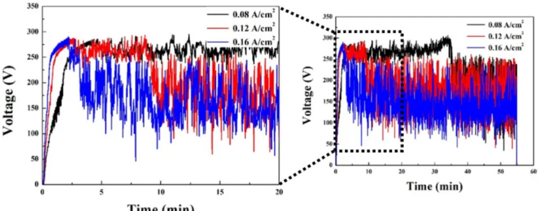
그림 3은 duty cycle 20% 조건에서 인가전류밀도 를 각각 다르게 하여 1시간동안 MAO를 하는 동안 의 시간-전압 그래프이다. 전류가 인가되면서 금속 표면에서 생기는 산화층으로 저항이 증가하여, 그 에 따라 전압도 선형적으로 상승되는 것을 확인할 수 있었으며 이후 시간이 지나면 전압의 상승률이 현저하게 감소하여 어느정도 일정한 임계전압(약 290 V) 에 도달하였다. 그러나 코팅시간이 어느정 도 길어지면 전압곡선이 심하게 요동치는 곳에서는 방전이 어느 한 부분만 집중적으로 일어나는데 0.08 A/cm2조건에서는 약 35분 지점에서, 0.12 A/cm2조 건에서는 약 10분, 0.16 A/cm2 조건에서는 약 2분 지점에서부터 심한 요동이 일어났다. MAO 공정에 서 전압이 심하게 요동치는 것은 방전이 소멸되는 것을 의미하며 [26] 특정 부분에서만 플라즈마 방 전이 일어나고 나머지 부분은 이러한 반응 없이 알
Fig. 2. SEM images of surface morphology for MAO coated Al6061 with duty cycle of 20%. They have been
prepared by different current densities and anodizing time conditions. (a) 0.08 A/cm
2for 10 min, (b) 0.12 A/cm
2for
10 min, (c) 0.16 A/cm
2for 10 min, and (d) 0.08 A/cm
2for 30 min, (e) 0.12 A/cm
2for 30 min, (f) 0.16 A/cm
2for 30 min,
(g) 0.08 A/cm
2for 1 hr, (h) 0.12 A/cm
2for 1 hr, and (i) 0.16 A/cm
2for 1 hr, respectively.
424 김남열 외/한국표면공학회 50 (2017) 421-426
칼리 전해질에 노출되며 지속적인 산화층의 용출이 일어난다. 따라서 이 구간 이후에는 균일한 MAO 코팅의 균일성을 기대하기 어려우며 그림 2와 상응 하는 결과를 보였다.
그림 4는 duty cycle을 80% 로 조정하여 마찬가 지로 10분, 30분, 1시간동안 MAO를 한 시편의 표 면을 SEM으로 관찰한 것이다. 먼저 (a)~(i) 전체적 으로 그림 2와 마찬가지로 코팅시간이 길어질수록 표면의 균일도는 떨어지는 것이 확인되었으며 duty
cycle을 제외한 나머지 조건이 같을 때, 그림 4에선 크기가 큰 기공과 크레이터가 훨씬 더 많이 생성되 었음을 확인할 수 있었다. 또한 duty cycle 20% 조 건의 그림 2와는 달리 인가전류밀도가 커질수록 이 러한 불균일도가 더 증가하는 것을 확인할 수 있었 다. 특히 (a)~(f) 에서 보이던 기공이 (g)~(i) 에선 형태를 알아볼 수 없을 정도로 표면상태가 좋지 않 았다. 이는 duty cycle 20% 조건보다 잦은 플라즈 마 방전으로 인한 것이며 용융된 산화층이 짧은 휴
Fig. 3. Time-Voltage transients during MAO coating process with duty cycle of 20 % for 1 hr.
Fig. 4. Surface morphology images obtained with duty cycle of 80% and different current density and coating times.
(a) 0.08 A/cm2, (b) 0.12 A/cm2, (c) 0.16 A/cm2 for 10 min, and (d) 0.08 A/cm2, (e) 0.12 A/cm2, (f) 0.16 A/cm2 for
30 min, and (g) 0.08 A/cm2, (h) 0.12 A/cm2, (i) 0.16 A/cm2 for 1 hr.
지기(pulse off time)를 가져 충분한 냉각단계를 거 치치 못하였기 때문이라고 생각된다. 따라서 균일 한 표면을 가지는 MAO 코팅을 위해서는 낮은 duty cycle 을 가져 용융된 산화층이 자리를 잡고 충분 한 냉각단계를 거쳐야 한다는 결론을 도출하였다.
그림 5는 그림 3과 마찬가지로 duty cycle 80%
조건에서 인가전류밀도를 달리하여 1시간동안 MAO 를 하는 동안의 시간-전압 그래프이다. 그림 3과 비 교하였을 때 잦은 플라즈마 방전에 의하여 임계전압 에 도달하는 시간이 빠르며, 전압이 심하게 요동치 는 시점도 빨라짐을 확인할 수 있었다 (0.08 A/cm2 조건에서 약 1.5분, 0.12 A/cm2 조건에서 약 1분, 0.16 A/cm2 조건에서 약 30초). 이는 특정 부분에 서의 방전이 일어나면서 반응이 일어나지 않는 나 머지 부분들이 용액에 노출되는 시간이 길어짐에 따라 용액으로의 용출도 더 많이 되었음을 의미하 며 그림 4와 상응하는 결과를 보여주었다.
4. 결 론
본 연구에서는 Al6061 합금 표면위에 unipolar pulse를 이용한 MAO를 균일한 산화층을 형성하였 다. 여러가지 전기적 변수 중 전압을 제어하는 방 법보다 전류밀도를 제어하는 방법이 더 균일한 표 면구조의 산화층을 만들 수 있었다. 이후 긴 시간 동안 전류밀도를 pulse 파형으로 인가할 경우, duty cycle이 작을 때는 전류밀도가 높을수록, duty cycle 이 높을 경우 전류밀도가 낮을수록 더 균일한 표면 구조의 MAO피막을 얻을 수 있었으며, 전체적으로 duty cycle을 낮춤으로써 더 균일한 표면구조의 MAO피막을 얻을 수 있었다. 또한 일정 시간이 흐 른 뒤 전압이 심하게 oscillation이 되고 플라즈마 방전이 국부적으로 동일한 지점에서 반복적으로 일 어나는 현상이 나타나 피막이 국부적으로 파손되어
균일하지 못한 표면구조의 MAO 피막을 형성하였 다. 따라서 균일한 MAO 코팅층을 위해선 duty cycle을 낮게 하고 전류밀도는 높이되, 전압이 임계 전압에서 유지할 수 있는 적절한 시간동안 MAO를 진행시켜야 함을 알 수 있었다.
감사의 글
본 논문은 대전지역사업평가단 경제협력권산업육 성사업 지역주도형 선정과제 연구비를 지원받아 수 행된 연구임. (과제번호 55015-01)
References