위성시스템 강우 감쇠 보상을 위한 ACM 성능 시뮬레이션
장매향*, 김수영* 종신회원, 백정기**, 김인겸***
Performance Simulation of ACM for Compensating Rain Attenuation in Satellite Link
Meixiang Zhang*, Sooyoung Kim*, Lifelong Member, Jeong-Ki Pack**, Ihn-Kyum Kim***
요 약
Ku 대역 이상의 고주파수 대역을 사용하는 위성통신 시스템의 링크 성능 저하의 가장 큰 요인인 강우 감쇠를 효과적으로 보상할 수 있는 방법으로 적응형 전송 방식을 들 수 있다. 본 논문에서는 국내 Ka 대역 강우 환경에 적합하도록 개발된 동적 강우 감쇠 모델을 탑재하여 구현된 적응형 강우감쇠 보상 시뮬레이터을 제시한다. 본 논문에서 소개된 시뮬레이터에는 초 단위 강우 감쇠 실측 데이터에 대한 통계치를 바탕으로 추출된 강우 파라미터가 적용된 동적 강우 감쇠 Markov chain 모델이 탑재되어 있다. 또한, 여러 가지 전송 기법들을 구비하여 사용자의 요구 사항에 따른 다양한 시뮬레이션이 가능하도록 하였다. 본 논문에서 는 또한 적응형 전송기법을 이용하여 시뮬레이션한 결과를 고정형 전송기법의 결과와 비교함으로써, 적응형 전송 기법의 활용이 효과적으로 강우 감쇠를 보상할 수 있음을 보였다.
Key Words : satellite communications, rain attenuation, adaptive transmission, time-series generator, Markov chain.
ABSTRACT
Adaptive transmission technique is an effective means to counter-measure rain attenation that is one of the most significant factors degrading link quality in satellite communication systems. This paper introduces a simulator for adaptive transmission technique to compensate rain attenuation. In the simulator, a dynamic rain attenuation model is loaded, which was developed to synthesize Korean rain attenuation dynamics at a frequency band of Ka. It is a Markov chain model with rain attenuation parameters extracted from the rain attenuation data measured per second. In addition, various transmission schemes are embedded so that a user defined simulations can be performed. This paper demonstrates simulation results of adaptive schemes in comprison with fixed schemes, and show the efficiency of the adaptive schemes to compensate the rain attenuation.
※이 논문은 국방과학연구소의 재원으로 충남대학교 산학협력단의 지원을 받아 수행된 연구 결과임
*전북대학교 전자정보공학부 IT융합연구센터 ([email protected], [email protected]),
**충남대학교 전파공학과 ([email protected]),
***국방과학연구소, 교신저자 : 김수영
접수일자 : 2012년 10월 18일, 수정완료일자 : 2012년 10월 26일, 최종게재확정일자 : 2012년 11월 12일
I. Introduction
Signal fading due to rain is one of the most significant factors degrading link quality in satellite communication systems using high frequency bands such as Ku and Ka bands. In order to achieve about 99% of link availability, around 11-12 dB of link margin is required in the system using Ka-band. However, to achieve another 0.9% of link availability, more than 20 dB of link margin is required [1].
It is not cost-efficient to allocate a large static power
margin to compensate rain fading during such a small time period.
For this reason, in order to increase system availability, an adaptive transmission technique with a control algorithm to adaptively allocate adaptive coding and modulation (ACM) schemes is used as a countermeasure to rain attenuation. This paper introduces a simulator for adaptive transmissions over Ka-band satellite communication channel to compensate rain attenuation.
The simulator is equipped with a rain attenuation model
which synthesizing the dynamics of rain attenuation, along with various transmission schemes for utilization of ACM. For synthesization of rain attenuation, a 4-state Markov chain is used to characterize the dynamic of rain fading channel. For effective dynamic allocation of adaptive schemes, a prediction and a allocation algorithms are used. Prediction of signal quality due to rain attenuation is based on historical rain information.
Subsequently, allocation of transmission schemes according to the predicted signal quality us made [2].
The remainder of this paper is ordered as follows.
Basics on the ACM simulator including the system configuration and the theoretical basics on the essential functional blocks will be briefly explained in Section 2.
Details on the ACM simulator including the parameters are introduced in Section 3. Section 4 demonstrates the simulation results of ACM schemes for compensating rain attenuation in satellite link in comparison with those of fixed schemes. Conclusions will be drawn in Section 5.
2. Basics on the ACM simulator
2.1 System configuration
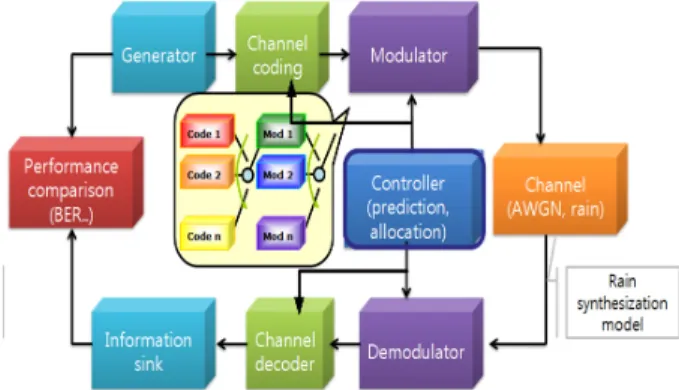
The structure of the ACM simulation system is shown in Fig. 1. In the transmitter part, after random bit generation, channel coding and modulation schemes are equipped with a number of choices. Allocation of these schemes is made by the controller which is the most important part of the ACM systems. The controller first predicts the signal quality based on the observation of the previous received signal as in Section 2.3, and it allocates appropriate coding and modulation schemes as in Section 2.4.
During the transmission through the satellite channel, the signal strength may be faded by rain attenuation which is synthesized by a Markov chain model in the simulator. At the receiver part, there are demodulators and channel decoders corresponding to the modulators and channel encoders in the transmitter part. Finally, the decoded information is compared with the generated information, and the performance is estimated in various aspects including bit error rate (BER), outage, spectral efficiency, and etc.
Fig 1. Structure of the ACM system in a satellite link
2.2 Rain dynamics synthesization
In our previous research, rain attenuation models to synthesize the dynamic of rain fading for satellite systems using Ka-band are developed [3]-[5]. In these models, it is assumed that a rain event can be characterized by a 4-state Markov chain. That is, a rain event is consisted of a beginning, a fading, an ending and an inter-fade state with a duration of ,, and ,respectively, as shown in Fig. 2 [3][5]. In Fig. 2, ∈ is the transition probability of state changing from states to , is the rain attenuation, and is the slope of the attenuation.
Fig 2. 4-state Markov chain for rain attenuation process.
Using the statistical properties investigated in each state, rain attenuation events can be synthesized. For each state , the random variable is first generated when the state begins. Subsequently, and are generated to synthesize the rain attenuation [5].
2.3 Prediction of rain attenuation
Allocation of an appropriate transmission scheme according to the channel condition should be made on the basis of the prediction by considering the round-trip delay.
Signal quality due to rain attenuation needs to be predicted prior to the transmission. Intelligent control algorithms has
been developed to adaptively allocate transmission schemes by estimating and predicting rain attenuation [2].
The scheme predicts the signal level, , after a prediction time, , from the previous signal levels, using the following equation:
(1)
where is observation time, is the weighting factor at time , is the signal level at current time , and is the signal level at indicating historical channel information. One of the simplest implementation of (1) uses two constant weight value for two end points of the observation period and assumes that future variation of the signal level will remain the same as the previous variation. This method was referred as slope based prediction (SBP) [2], and it is employed in the ACM simulator.
2.4 ACM allocation
For adaptive rain compensation, a real time resource allocation algorithm is required to select an appreciate transmission scheme. Allocation should be made with the best spectral efficiency and performance under the current signal level [2][6][7]. The algorithm selects a transmission scheme, , having the maximum throughput under a current SNR such that
∈
(2)
where is the accumulation period, is the number of available transmission schemes and is the throughput normalized by the data rate of the transmission scheme , which can be obtained by
(3)
where is the BER value for the predicted SNR
. When is larger than the required BER, the BER is replaced by the value of 1 in order to give penalty to the selected scheme. The weighting factor is determined by:
(4)
where is a parameter that adjusts the sensitivity of
to the slope.
3. Simulator configuration
3.1 Basic structure
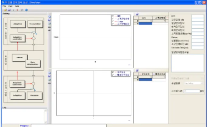
Figure 3 shows initial display window of the simulator after logging in. The left part of the window shows the data flow of the communication system, on which we can set the simulation parameters by clicking the corres- ponding blocks. In addition, the parameter value can be set in the main menu. Two graphs in the middle parts of the window display the dynamic results during the simulation.
The upper graph is used to display one of the results among BER, spectral efficiency, outage rate, the required power margin, while the lower graph is used to display both the current and predicted rain attenuation values. The rightmost shows the text display of the dynamic simulation results along with the parameters used in the simulation.
Fig 3. Initial display window of the ACM simulator
3.2 Parameter setting
Figure 4 shows an example of system parameter setting window. System parameters are used to define the characteristics of the target simulation system, including the simulation time (시뮬레이션 시간) in second or in the number of errors as a condition to terminate the simulation. Other system parameters include transmission rate in symbols per second, the required BER in the unit of exponent of (e.g. In Fig. 4, “요구 BER” of 5
indicates of BER), and the power margin in dB. as shown in Fig. 1. In this window, we can also set either we want simulation with adaptive coding and modulation (ACM) mode (적응형 전송방식) or simulation with fixed mode (고정형 전송방식).
Fig 4. Example of system parameter setting
Figure 5 shows the parameters of the transmitter and receiver in ACM scheme. As we can see from Fig. 5, we can select different ACM modes either an uncoded ACM mode or coded ACM mode. Allocation interval is used to determine how often we allocate different ACM modes.
The minimum (최소 변조방식) and maximum modulation (최대 변조방식) schemes are parameters used to regulate levels of the modulation schemes employed in the ACM operation.
Fig 5. Example of transmitter and receiver parameter setting for an ACM mode
As we can see from Fig. 5, just below the “ACM modes” selection either with “Coded” or “Uncoded”, there is a button for “Edit Userdefined File”. In each of ACM mode, the simulator uses the parameter file which was written for the ACM operation. Therefore, if a user want
to operate another ACM mode with different combinations of coding and modulation schemes, then the user may use the userdefined parameter file which was written with the same protocol. An example of the parameter file for the
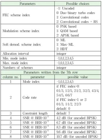
“Uncoded” ACM operation is shown in Fig. 6, and explanations on the parameter values are shown in Table 1.
Fig 6. Example of the parameter files for “Uncoded”
ACM operation mode.
Table 1. Values in the parameter files for ACM mode operation.
Parameters Possible choices
FEC scheme index
-1: Uncoded
0: Duo-binary turbo codes 1: Convolutional codes 2: Convolutional codes + RS
Modulation scheme index
0: PSK based 1: QAM based 2: APSK based
Soft demod. scheme index
0: ML 1: Max-ML 2: HDT Allocation interval integer Min. mode index -1,0,1,2,3,4,5 Max. mode index -1,0,1,2,3,4,5 Numbers of schemes integer
Parameters written from the 7th row column no. parameter possible value
1 Mode index -1,0,1,2,3,4,5
2 Code rate
if FEC index=0:
0:1/3, 1:2/5, 2:1/2, 3:2/3, 4:3/4, 5:4/5, 6:6/7
if FEC index=1 or 2:
0:1/3, 1:1/2, 2:2/3 default: 0 3 Constraint length default: 7
4 SNR @ BER=10-2 4.2 dB (for uncoded BPSK) 5 SNR @ BER=10-3 6.7 dB (for uncoded BPSK) 6 SNR @ BER=10-4 8.3 dB (for uncoded BPSK) 7 SNR @ BER=10-5 9.6 dB (for uncoded BPSK) 8 SNR @ BER=10-6 10.7 dB (for uncoded BPSK)
Figure 7 shows an example of transmitter and receiver parameter setting for a fixed mode, where we can select a forward error correction method (FEC 방식) among
uncoded, convolutional coded and convolutional code combined with Reed Solomn (RS) codes along with modulation and demodulation schemes.
As modulation schemes (변조 방식), there are phase shift keying (PSK) based, quadrature amplitude modulation (QAM) based, amplitude phase shift keying (APSK) based modulation schemes. There are 5 basic modulation orders regardless of the modulation scheme choices, and they are 4RS_BPSK, 2RS_BPSK, BPSK, QPSK, and 8-PSK, where RS represents repetition of symbols. In addition, there are 16-PSK for PSK based, 16-QAM and 64-QAM for QAM based, 16-APSK and 32-APSK for APSK based modulation schemes.
As soft demodulation schemes for iterative decoding (반 복복호를 위한 연판정 복조 방식), there are maximum likelihood (ML), Max-ML, hard decision threshold (HDT) based demodulation schemes.
Every ACM combination is applicable except 16-APSK or 32-APSK with convolutional coded or concatenated convolutional codes combined with Reed Solomn codes.
Fig 7. Example of transmitter and receiver parameter setting for a fixed mode
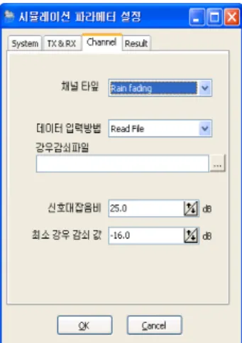
Channel parameters are used to determine the characteristics of the satellite channel as shown in Fig. 8.
We can choose the channel type (채널 타잎) to be an AWGN or rain fading channel. If rain fading channel is selected, there is an option to select rain date to be read from the file or synthesized by using the model developed in [3]-[5]. Signal to noise ratio (SNR) is determined in this setting. The minimum rain attenuation value (최소 강우 감 쇠 값) is the minimum rain attenuation value generated by the synthesized model. A user can also use another rain attenuation data file available.
Fig 8. Example of Channel parameter setting
There are various methods to estimate the performance, the choice of displays can be set as shown in Fig. 9. As we can see from Fig. 9, we can set the period of dynamic output of the BER (동적 BER 표기 주기) as we want.
Fig 9. Example of result display setting
4. Simulation results
In this section, we present simulation results of ACM operation in rain faded satellite communication link. Table 2 shows the simulation parameters we used to estimate the performance of ACM systems. The adaptive modulator and the demodulator select one of -PSK schemes according to the control signal that is produced by the selection algorithm.. Six modulation orders of -PSK schemes are used includuing 4RS_BPSK, 2RS_BPSK, BPSK, QPSK, 8-PSK, 16-PSK. The link margin of 2 dB is used to compensate the prediction and allocation errors of the control algorithm.
Table 2. Parameters of simulation system.
System parameters
Simulation time 2000 seconds
Frequency band 22 GHZ
Symbol rate 9600 symbols/second
Link margin 2 dB
Required BER
SNR 25 dB
Other parameters
Minimum fading depth -16 dB Rain attenuation type Measured rate data
Prediction time 1 second Observation time 2 seconds Allocation interval 1 second
Coding scheme Uncoded / Conv. codes Demodulation type Maximum likelihood (ML)
4.1 Results from the ACM schemes
Figure 10 shows the current and the predicted rain attenuation values. In order to see if the predicted value reasonably follows the real rain attenuation data, Figure 9 (b) shows the first 450 seconds of the whole simulation time in (a), and it shows the predicted value are almost the same as the real rain attenuation value.
(a) Rain attenuation value of 2000 seconds
(b) The first 450 seconds of (a)
Fig 10. Rain attenuation value with the predicted value
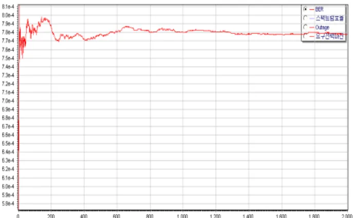
Figure 11 shows the dynamic BER performance variation during the simulation time for the uncoded ACM scheme. As we can see, during the whole simulation time,
the BER value does not exceed the required BER of . Table 3 shows the occupancy rate of various modulation orders employed in the uncoded ACM operation during the whole simulation time.
Fig 11. Dynamic BER performance of the uncoded ACM mode
Table 3. Occupancy rate of various modulation orders in the uncoded ACM scheme
Modulation order Occupancy rate
4RS-BPSK 0.000500
2RS-BPSK 0.012494
BPSK 0.062969
QPSK 0.209895
8-PSK 0.668166
16-PSK 0.045477
Figure 12 shows the BER performance of an convolutional coded ACM scheme, and Table 4 shows the corresponding occupancy rate of modulation orders. In the coded scheme, we used a fixed code rate of 1/3, and a constraint length of 7. Because of the coding gain by utilization of the convolutional code, only higher order modulation schemes are utilized as in Table 4.
Fig 12. Dynamic BER performance of the convolutional coded ACM mode
Table 4. Occupancy rate for modulation orders with convolutional coded ACM schemes.
Modulation scheme Occupancy rate
QPSK 0.030485
8-PSK 0.180410
16-PSK 0.788606
4.2 Results from the Fixed schemes
Figure 13 and 14 show examples of BER performance simulation results with fixed modes. The BER performance in Fig. 13 is the result with an uncoded QPSK over an AWGN channel with SNR of 10 dB, which shows the same result of as the theoretical value.
Fig 13. BER performance of the uncoded QPSK over an AWGN at SNR = 10 dB
The BER performance shown in Fig. 14 is the result with an uncoded 16-PSK over rain attenuation channel with SNR of 25 dB. As we can see from it, the performance degradation is serious due to the rain attenuation without any power margin.
Fig 14. BER performance of the uncoded 16-PSK over rain attenuation channel at SNR = 25 dB
4.3 Performance comparison
Table 5 shows the comparison of various ACM and
fixed schemes in terms of BER, effective spectral efficiency and outage rate over rain attenuation channel with the parameter in Table 2. The ACM schemes can not only achieve the required BER but also have high effective spectral efficiency, while the fixed scheme can only either achieve the required BER with small outage rate or get high effective spectral efficiency with very high outage rate.
Table 5. Comparison of ACM and fixed modes over rain attenuation channel
Scheme BER
Effective spectral efficiency
Outage rate
Uncoded ACM × 2.68 0.06
Coded ACM × 3.76 0.02
UncodedQPSK × 1.00 0.00 Uncoded 16-PSK × 3.97 0.90
5. Conclusion
In this paper, we introduced an ACM simulator which was developed to estimate the performance of satellite system over a rain-faded channel. We presented the details of the parameters of the ACM system. In addition, we demonstrated the performance simulation results of both uncoded and convolutional coded ACM schemes in comparison with fixed schemes. From the results, we can see that the designed ACM system can achieve the required BER using the appropriate scheme allocated under the predicted channel condition. The simulator can employ a user defined ACM mode, and the performance of each independent coding and modulation scheme included in the ACM can be obtained from the fixed mode simulation.
참 고 문 헌
[1] Sooyoung Kim Shin, Soo In Lee, Yang Su Kim, and Jae Moung Kim, “A Dynamic Rain Attenuation Modeling Technique for SatelliteCommunication Link”, Proceedings of International Conference on Telecommunications, vol. 2, pp.
33-37, Jun. 1999.
[2] Sooyoung Kim Shin, Kwangjae Lim Kwonhue Choi, and Kunseok Kang, “Rain attenuation and Doppler Shift Compensation for Satellite Communication”, ETRI Journal, vol. 24, no. 1 pp. 31-42, Feb. 2002.
[3] Meixiang Zhang, Sooyoung Kim, Jeong-Ki Pack, “A
Dynamic Rain Attenuation Model for Adaptive Satellite Communication Systems”, Proceedings of 7th WiMob, 10 Oct-12 Oct. 2011.
[4] Meixiang Zhang, Jeong-Ki Pack, “A Dynamic Rain Attenuation Model for Adaptive Satellite Communication Systems”, The journal of the korea society of space technology, vol. 6, no. 1, pp. 12-18 , Jun. 2011.
[5] Meixiang Zhang, Sooyoung Kim, Jeong-Ki Pack and Ihn-Kyun KIM, “A Statistical Approach for Dynamic Rain Attenuation Model”, Proceeding of 29th AIAA ICSSC, 28 Nov.-1 Dec. 2011.
[6] Sooyoung Kim Shin, Kwangjae Lim, Hyoungsoo Lim, Taegon Kweon, and Soo In Lee, “Adaptive Rain Fade Compensation Technique and Its Performance Evaluation,”
Proc. of the 5th CDMA Int'l Conf., vol. 2, Nov. 2000, pp.
592-596.
[7] Kwang-Jae Lim, Soo In Lee, and Seong Pal Lee,
“Radio-Format Selection Algorithm for Rain-Fade Compensation in Adaptive Satellite Communication", Proc.
of the 6th Ka-band Utilization Conf., Jun. 2000, pp. 209-216
저자
장 매 향(Meixiang Zhang)
․2009년 7월 : 중남민족대학교 컴퓨터공 학 학사졸업
․2012년 8월 : 전북대학교 전자정보공학 부 석사졸업
․2112년 9월 ~ 현재: 전북대학교 전자 정보공학부 박사과정
<관심분야> : 위성통신, 디지털 통신
김 수 영(Sooyoung Kim) 정회원
․1990년 2월 : 한국과학기술원 전기 및 전자공학과 학사졸업
․1990년 ~ 1991년 : ETRI 연구원
․1992년 : Univ. of Surrey, U.K 공학석사
․1995년 : Univ. of Surrey, U.K 공학박사
․1994년 ~ 1996년 : Research Fellow, Univ. of Surrey, U.K
․1996년 ~ 2004년 : ETRI 광대역무선전송연구팀장
․2004년 ~ 현재 : 전북대학교 전자공학부 부교수
<관심분야> : 오류정정부호화방식, 이동/위성통신 전송방식
백 정 기(Jeong-Ki Pack)
․1978년 2월 : 서울대학교 전자공학과 (공학사)
․1985년 9월 : Virginia Tech. 전자 파전 파 (공학석사)
․1988년 9월 : Virginia Tech. 전자파 전 파(공학박사)
․1978년 3월 ~ 1983년 2월 : 국방과학연구소
․1988년 10월 ~ 1989년 2월 : 한국전자통신연구원
․1989년 3월 ~ 1995년 2월 : 동아대학교 전자공학과 부교수
․2009년 1월 ~ 2009년 12월 : 한국전자파학회 회장
․1995년 2월 ~ 현재 : 충남대학교 전파공학과 교수
․2002년 3월 ~ 현재 : 충남대학교 전자파환경기술연구 (EMERC) 센터장
<관심분야> : 전자파 전파, 전자파 산란, 전자파 인체 영향
김 인 겸
․1988년 2월 : 한양대학교 전자통신공학 과 (공학사)
․1990년 2월 : 한양대학교 전자통신공학 과 (공학석사)
․1990년 3월 ~ 현재 : 국방과학연구소 책임연구원
<관심분야> : 광대역 무선전송 및 군 위성통신 시스템 기술, 전자파 전파