www.kosse.or.kr
Preliminary Hazard Analysis: Assessment of New Component Interface Module Design for APR1400
*
Adebena Oluwasegun Olaide, Jae Cheon Jung, Moon Jae Choi, Utah Michael Ngbede KEPCO International Nuclear Graduate School (KINGS)
Abstract : The use of Field-Programmable Gate Arrays (FPGAs) in the development of safety-related Human-Machine Interface (HMI) systems has gained much momentum in nuclear applications. Recently, one of the application areas for the Advanced Power Reactor 1400 (APR1400) is in the development of the advanced Component Interface Module (CIM) of the Engineered Safety Features Actuation System (ESFAS).
Using systems engineering approach, we have developed a new FPGA-based advanced CIM software. The first step of our software development process involves the Preliminary Hazard Analysis (PHA) based on the previous CIM design. In this paper, we describe the qualitative approach used in performing the preliminary hazard analysis. The paper presents the methodology for applying a modified Hazard and Operability (HAZOP) procedure for the conduct of PHA which resulted in a qualitative risk-ranking scheme that informed the decisions for the safety criteria in the requirements specification phase. The qualitative approach provided the justification for design changes during the advanced CIM software development process.
Key Words : Hazard Analysis, PHA, PHL, Software Hazard, CIM, Risk Matrix, Systems Engineering
Received: November 25, 2020 / Revised: May 24, 2021 / Accepted: June 21, 2021
*
교신저자 : Adebena Oluwasegun Olaide/[email protected]
This is an Open-Access article distributed under the terms of the Creative Commons Attribution Non-Commercial
License(http://creativecommons.org/licenses/by-nc/3.0) which permits unrestricted non- commercial use, distribution,
and reproduction in any medium, provided the original work is properly cited
1. Introduction
The interest and momentum in the deployment of Field Programmable Gate Array (FPGA) technology for safety-related digital instrumentation and control (I&C) systems of nuclear power plants show an increasing trend .[1],[2] In the Advanced Power Reactor 1400 (APR1400), one of the application areas is in the development of the FPGA-based advanced Component Interface Module (CIM) of the Engineered Safety Features Actuation System (ESFAS). The CIM interfaces the safety actuation command signals from safety systems to the plant’s field components such as pumps, valves, and dampers to allow for automatic and manual control of safety components on demand. The design of such a FPGA-based system relies on software environments and hardware description languages that fundamentally define the system’s logic functions and can consequently contribute to the exhibition of unexpected behavior by the system due to design errors.[3] One major consequence of this type of issue for safety-critical systems is that it has the potential to put the nuclear reactor into a hazardous state in which there is a loss of the prevention of the release of radioactive fission materials.[4] Therefore, the design and analysis of digital systems must be such that failures result in a predictable and acceptable range of system behaviors.
In the development process of an FPGA-based system, it is essential to analyze the design to ensure that the system’s behaviour is deterministic during a failure and that the hazards are acceptably safe. This
implies investigating the various hazard mechanisms and the associated risks concerning nuclear power plant safety. IEEE Std. 7-4.3.2 [9] requires the identification and resolution of hazards with the potential to defeat a safety function. Also, ISO/IEC/IEEE 15288 [22] emphasizes the importance of conducting hazard assessment during a system life cycle development process. Typically, the starting point of this kind of hazard investigation is the Preliminary Hazard Analysis (PHA). PHA is an initial top-level safety analysis for identifying hazards, hazard causes, effects, initial risk level, and the potential mitigation measures during the conceptual and preliminary design stages of system development.[5] PHA provides early guidance on the system’s safety requirements that will integrate into the development life cycle of the system.
From a software perspective, the IEEE Std.
1228 [6] requires that a PHA be available before performing any of the suggested safety analyses during a software development process. Also, the NUREG/CR-6430 [4]
describes many techniques for performing
hazard analysis at various stages of software
development. However, beyond stating that the
PHA is a prerequisite step for performing
other hazard analyses, the IEEE Std. 1228 and
the NUREG/CR-6430 provide little information
about the actual conduct of PHA. Nonetheless,
it is important for design engineers to evaluate
all credible hazards during system
development. From a general viewpoint, there
are three ways to evaluate hazards: (1)
qualitative method, (2) quantitative method,
and (3) hybrid method. Since, both elements
of risk - hazard severity and likelihood - must be characterized in hazard evaluation studies, the choice of any approach depends on the method of risk probability estimation and the final objective of the hazard analysis.[7]
The quantitative method involves a detailed risk assessment with the unit of probability expressed in rate and calculated from failure rates of components. On the other hand, the qualitative method estimates risk following an established likelihood criteria. In PHA studies, it is not necessary to quantitatively estimate risk since the final objective is to have a broad-scope view of the system’s hazards at the preliminary stage. Notwithstanding, there exist many hazard analysis techniques in literature that cut across these three general classifications. NUREG/CR-6430 listed some 47 techniques with potential application to software hazard analysis. Among these techniques, the classical Hazard and Operability (HAZOP) study is comparably easy to use for a PHA study.
This paper describes the use of a modified HAZOP method for performing preliminary hazard study of an FPGA-based CIM design.
The study is based on the design entry at the concept phase of the advanced CIM project development. The paper outlines the systems engineering (SE) framework for hazard analyses and expands the application of the classical HAZOP method to the PHA study of the CIM. The modification of the traditional HAZOP method is one of the focus areas of this PHA study.
The other sections of this paper are as follows: Section 2 introduces the background for SE consideration in the life-cycle process
for hazard analyses and the life-cycle process for FPGA application design. It also discusses related research work. Section 3 describes the PHA methodology and the process workflow used for performing the hazard investigation.
Section 4 is the result section that shows the outcome of our hazard analysis on a PHA worksheet. Section 5 concludes our approach for performing the preliminary hazard analysis.
2. Background
2.1 Life cycle process of hazard analyses A hazard is a condition or event or the presence of a potential risk situation that can be internal or external to a system that leads to an accident.[8] IEEE Std. 7-4.3.2 requires the identification, evaluation, and resolution of hazards that have the potential to defeat safety functions. Therefore, it is necessary, during each system development phase, for design engineers to provide adequate assurance of all hazard resolution. In order to obtain this assurance, the hazard analysis process must exist within the systems engineering management framework. The framework can be domain specific to achieve higher engineering success as proposed by.[24]
Kossiakoff [23] describes the systems
engineering framework for a typical waterfall
model. NASA-GB-8719.13 [8] describes the
various hazard analyses within the elements of
the system’s life cycle from the conceptual
phase to the operation phase for the waterfall
model, as depicted in Figure 1. The figure
illustrates the relationship between the various
stages of hazard analyses and the stages of a
typical waterfall life-cycle model. Each level of hazard analysis is to identify and eliminate or reduce potential hazards as much as possible. The PHA cuts across the three stages of concept development, requirements phase, and preliminary architecture design.
The PHA is based on a baseline conceptual design and forms the foundation for other hazard analyses. It establishes the initial system safety criteria at the early stage of development. During system development, the initial safety criteria are flown down to the requirement specifications. Detailed criteria are then generated from a Requirements Hazard Analysis (RHA) that uses the PHA results as inputs along with other industrial and regulatory requirements. Typically, hazards are tracked throughout the entire analysis process and the PHA is continuously updated.
2.2 Life cycle model of FPGA application design
The design of an FPGA logic is by writing a program into an FPGA chip using a hardware
description language (HDL). FPGA devices are hardware-based but the design of logic functions into the FPGA device depends on a software environment. Several standards and regulatory bases exist that describe the development process for FPGA applications in Nuclear Power Plant (NPP) I&C systems. For instance, EPRI TR 1019181 [10] provides guidelines for FPGA design, modification planning, implementation, and verification processes. NUREG/CR-7006 [11] identifies the design life cycle and the design flow for FPGA application. The IEC 62566 [12]
provides the general requirements for the development life cycle of FPGA-based system.
Figure 2 shows a typical life-cycle model and the design flow for an FPGA-based application described by.[13] The life-cycle model of the FPGA application development follows the traditional V-model with the associated verification and validation (V&V) process. The input to the FPGA application design process is a set of technical requirements and design architecture
[Figure 1] Hazard analysis tasks within the life-cycle development
specifications. At the initial design stage, a preliminary design of the FPGA logic is generated and the associated design reviews include a hazard study. At the detailed design stage, the functional logic is generated using high-level HDL such as Verilog or the Very High-Speed Integrated Circuits HDL (VHDL).
Typically, the V&V process at this level includes safety analysis for functional simulation and static analysis. The detailed logic is finalized by the elaboration of logic artifacts and the synthesis of the Register Transfer Level (RTL) representation, which describes the behavior of the logic functions in terms of the signal flow between logic blocks.
At the first implementation stage of the FPGA application development process, the synthesizer transforms the RTL model into a netlist. A netlist defines the configuration for gate and interconnection requirements for the particular FPGA application being designed.
The second implementation stage is the Place and Route (PNR) which identifies the best physical positions on the chip for the logic blocks and the interconnections. This stage
leads to the generation of a bitstream, which is then loaded onto the FPGA chip.
Hazard analysis is part of the design and review processes for FPGA application design.
IEEE Std. 1012 [21] describes the various applicable hazard analysis tasks for system, software, and hardware development. Figure 2 highlights part of the targets of hazard analysis within the V&V process.
2.3 Research trends
For systems and software development processes, there are a few literatures that describe the application of hazard analyses for safety-critical systems in the nuclear power plant at different stages of the development life cycle. Jung et al. [14] describe the practical use of NUREG/CR-6430 for software requirements hazard analysis by redefining the analysis guide phrases and process to accommodate the analysis of circuit and memory aspects of the FPGA software requirements specification. They presented a case study to justify the applicability of their proposed method, by using a safety-related
[Figure 2] FPGA application design model
FPGA controller module and comparing the results obtained to that of a HAZOP analysis performed on the same software requirements specification. Their work is the most relevant hazard study to the work we present in this paper. Nevertheless, their paper is on software requirements hazard analysis, which presupposes that the prerequisite PHA study has been performed.
In a similar work, Li & Duo [15] presented a V&V model for software requirements safety analysis. They listed important safety activities and techniques to be performed during the requirement phase of software safety analysis and applied their analysis model to the landing gear control system as a case study. They determined that their approach is useful for specifying constraints on software processes and for verifying software safety requirements.
Bao et al. [16] propose the use of a modularized approach for conducting a system-wide hazard analysis for systems with multi-level redundancy design, to address the issue of common cause failures (CCFs) in hardware and software components. Their work considers the interaction and complexity of redundancy in system design and uses Fault Tree Analysis (FTA). They presented the application of their approach on a four-division digital ESFAS.
Similarly, Bai et al. [17] propose a colored Petri-Net-based software hazard analysis and modeling method for safety-critical digital systems that captures both software and hardware aspects and identifies potential CCFs in software. They demonstrated the application of their proposed method for the modelling and
analysis of the control logic for Main Steam Isolation Valve (MSIV).
The works of both Bao et al. and Bai et al.
are on system-wide approach of hazard due to CCF and inherently assume the availability of detailed system design information. A common attribute of the hazard analysis efforts described above is that they did not target the early stage of system development. Since important decisions that may affect system safety occur at the early stages of design, hazard analysis conducted afterward may fail to capture necessary safety criteria.
3. PHA methodology
The CIM PHA process used in this work is shown in Figure 3 and follows the general PHA process provided in.[5] The process involves six main steps of system definition, functional analysis, generic hazard checklist, Preliminary Hazard List (PHL), Hazard analysis, and risk level assessment. Table 1 describes the main steps of the analysis tasks.
SN Step Tasks
1 System Definition
Review concept, operations, functions, architecture, material and energy flow, components, interfaces, constraints, etc.
2 Analyze System
Review functional flow diagram, component layouts, etc.
3 Hazard Checklists
Acquire generic hazard checklists, lessons learned, failure modes, failure states, etc.
4 PHL Evaluate system elements & energy sources and compare them with hazard checklists.
5 Analyze Hazards
Evaluate system/software functions with hazard list. Identify hazards, causes, and effects. Build hazard worksheet
6 Evaluate Risk
Evaluate hazard severity, frequency, and risks.
<Table 1> Description of PHA tasks
[Figure 3] PHA process workflow
3.1 System definition and functional analysis Table 2 shows the system definition and the general decomposition of the CIM into operations, functions, architecture, and material & energy flow. Figure 4 shows the general CIM system architecture. The CIM consists of a base module, a communication module, and priority/feedback modules. The base module is a hardware assembly that provides I/O bus continuity, mechanical supports and interface for the other modules.
The communication module provides the I/O bus protocol and interfaces to the priority/feedback modules. The priority/
feedback modules provide the priority and component logic for safety signal commands for field component actuation. The priority logic is implemented in an FPGA chip. The CIM receives command signals from four sources, namely: the engineered safety features–component control system (ESF-CCS), the diverse protection system (DPS), the Diverse Manual Actuation (DMA) switch, and the local front panel switch. The
CIM prioritizes these control signals using priority logic and then sends the signal with the highest priority to a field component such as a pump, or a valve.
Operations
o Automatic control
o Local Manual control
o Remote Manual
o Setup & Maintenance
Functions
o Actuation control
o Priority command logic
o Feedback logic
o Signal interface
o Power interface
o Self-monitoring function
o User interface
o Diagnostic function
o Hot-swap function Architecture
o Base Module
o Communication Module
o Priority Module
o Feedback Module
Material Flow
o Command Signals
o Feedback Signals
o Energy Flow (DC, AC, surge, ESD)
<Table 2> System Definition
[Figure 4] CIM system architecture
3.2 Hazard checklist and PHL task
The next step in the PHA process workflow
is to generate hazard checklists and combine
the lessons learned from NPP into a
preliminary hazard list. The collation of hazard
checklists and the PHL tasks that we
performed is a structured process of
identifying hazards. We collated data from
generic checklists and combined them during our brainstorming sessions. Known hazard information from generic lists and lessons learned from event reports of plant protection systems were combined with CIM design information to generate a list of CIM hazards.
At this stage, we documented all possible suspected hazards in a structured manner. [5], [8] and [18] are the sources of our generic hazard checklists.
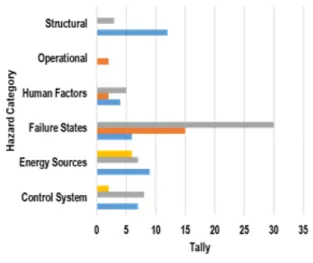
[Figure 6] Distribution of identified hazard
The checklists helped trigger recognition of potential hazards as elements from Table 2 were compared with the hazard elements on the checklists. The PHL was continuously updated during the brainstorming sessions each time we achieve a reasonable match that triggers ideas for potential hazards. Part of the PHL worksheet result is shown in Figure 10.
Figure 6 shows the distribution of the identified hazards, which indicates that most CIM failure-state hazards are related to the functions and modes of operation of the CIM.
Also, most of the structural and energy-source hazards are related to the CIM’s architecture. This helped us focus
attention on the safety criteria related to functions, operations, and architecture of the CIM design and provided guidance for the design engineers to pay more attention to the design of fail-safe features into the new CIM design.
3.3 HAZOP evaluation process
The process flowchart that describes the tasks undertaken for HAZOP evaluation is shown in Figure 7. The evaluation process starts with the use of the PHL result. For each identified hazard entity in the PHL worksheet, we evaluated causes, effects, and risks based on the estimation of severity and likelihood of the hazard. To implement this task in a structured manner, we developed a modified HAZOP worksheet.
There are two major reasons for considering the HAZOP technique. The first reason is that it provides a rigorous means of conducting hazard studies in a systematic and structured manner. The second reason is that since HAZOP can potentially identify design flaws in an existing system, it can also be used in our PHA study to evaluate existing CIM design considering that little design information is available for the new FPGA-based CIM design. Typically, HAZOP requires the use of guidewords in the analysis procedure and the technique is generally more suited for analysis in plant processes rather than in digital electronic systems.
We performed two modifications to the
traditional HAZOP procedure to meet our PHA
task requirements. The first modification is in
the use of guidewords. The guidewords
provided in [4] were used in this study with a
modification in the orientation of usage since they are primarily used for software requirements hazard analysis. The second modification is the inclusion of an additional requirement for hazard prioritization. We provided an additional grouping in the worksheet for safety-critical factor (SCF) and non safety-critical factor. In this way, reasonable consideration is given to a SCF that may have the same risk rank as a non safety-critical factor.
[Figure 7] Hazard evaluation process
The task flowchart of Figure 7 also shows the procedural activities of the hazard analysis.
First, we selected a hazard-system element pair and then identified relevant factors that would reveal hazardous scenarios for causes/effect using the guidewords. We then updated the worksheet accordingly with other entities such as severity, likelihood, risk rank, and suggested mitigation measures before moving to the next hazard-system pair.
3.4 Hazard risk index
Initial risk evaluation of each hazard is one of the main objectives of the PHA. Risk is generally estimated by combining hazard severity and likelihood. The classification of severity, likelihood, and risk index are provided in [4], [8], and [19]. NUREG/
CR-6430 recommends that the PHA task assign a preliminary severity rating to each hazard. Table 3 shows our modification of the severity rating reported in [4], [8], and .[19]
Below the negligible severity, which describes the condition for less than minor damage, we added a description for ‘Very Low’, which describes the case for no damage. In this way, we achieved a balanced assessment of hazard severity. Similarly, Table 4 shows the likelihood ranking used and describes the property of each level.
We used the risk ranking of Table 5 and the risk matrix of Table 6 to derive an estimate of risk for each hazard. Table 6 maps the hazard severity to the hazard likelihood to obtain a measure of the hazard risk. Thus, for instance, a hazard with ‘high’ severity and ‘medium’
likelihood evaluates to a ‘high’ risk using the risk matrix. The risk ranking of 4 or 5 indicates that greater resources need to be applied to the associated CIM component. The risk matrix of Table 6 was used for the qualitative risk assessment of the PHA.
Severity PHA Code Description
Catastrophic Very High (VH) System loss Critical High (H) Major system
damage Marginal Medium (M) Minor system
damage Negligible Low (L) Less than minor
system damage.
Very Low (VL) No damage
<Table 3> Hazard severity
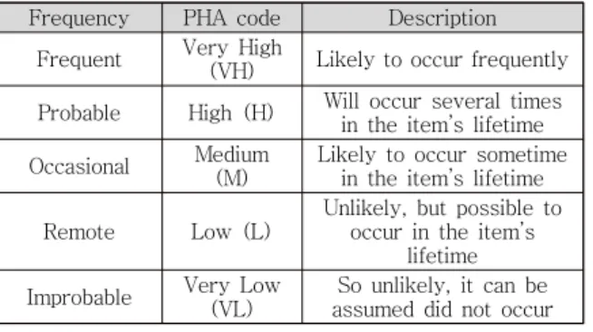
<Table 4> Hazard likelihood
Frequency PHA code Description Frequent Very High
(VH) Likely to occur frequently Probable High (H) Will occur several times
in the item’s lifetime Occasional Medium
(M)
Likely to occur sometime in the item’s lifetime
Remote Low (L)
Unlikely, but possible to occur in the item’s
lifetime Improbable Very Low
(VL)
So unlikely, it can be assumed did not occur
RR Description
5
Very High (VH)
4
![Figure 2 shows a typical life-cycle model and the design flow for an FPGA-based application described by.[13] The life-cycle model of the FPGA application development follows the traditional V-model with the associated verification and validation (V&a](https://thumb-ap.123doks.com/thumbv2/123dokinfo/4814779.523508/4.892.128.781.529.1078/application-described-application-development-traditional-associated-verification-validation.webp)