Thanh Cong Tran, Jae Cheon Jung* IKEPCO International Nuclear Graduate School
Abstract : This paper represents a systematic approach aimed at improving the performance of the proportional integral (PI) controller for the Advanced Power Reactor (APR) 1400 Feedwater Control System (FWCS). When the performance of the PI controller offers superior control and enhanced robustness, the steam generator (SG) level is properly controlled. This leads to the safe operation and increased the availability of the nuclear power plant. In this paper, a systems engineering approach is used in order to design a novel PI controller for the FWCS. In the reverse engineering stage, the existing FWCS configuration, especially the characteristics of the feedwater controller as well as the feedwater flow path to each SG from the FWCS, were reviewed and analysed. The overall block diagram of the FWCS and the SG was also developed in the reverse engineering process. In the re-engineering stage, the actual design of the feedwater PI controller was carried out using a genetic algorithm (GA). Lastly, in the validation and verification phase, the existing PI controller and the PI controller designed using GA method were simulated in Simulink/Matlab.
From the simulation results, the GA-PI controller was found to exhibit greater stability than the current controller of the FWCS.
Key Words : APR 1400 Feedwater Control System, PI Controller, Genetic Algorithm, A Systematic Engineering Approach
1. Introduction
The Advanced Power Reactor (APR) 1400 Feedwater Control System (FWCS) is designed to automatically control the steam generator water level by regulating the feedwater flow rate from the start-up mode to the power operation mode. The steam generator (SG) is one of the dynamic components in the Pressurized Water Reactor (PWR). It has a crucial role as a heat sink to the nuclear reactor and produces high- pressure steam for power conversion [1]. Therefore, stabilizing the required feedwater flow in the steam generator is essential to ensure that the APR 1400 nuclear power plant operates safely.
Thermodynamic phenomena such as Swelling and Shrinking in the SG cause the control of the SG water level to be difficult at lower power levels. The operation of the SGs is
determined by the power swing (0-100%
range), and plant shutdown. Moreover, the operating conditions of the control components, such as the feedwater pumps and the control valves, can differ from their condition at the start of operations. These factors may cause deterioration of the performance of the control system throughout the operational lifetime of the nuclear power plant [2]. The main controller of the FWCS is a proportional-integral (PI) controller. It consists of two primary parameters:
a reset time, and a gain constant. However, the existing PI controller in the FWCS cannot tackle the aforementioned problems.
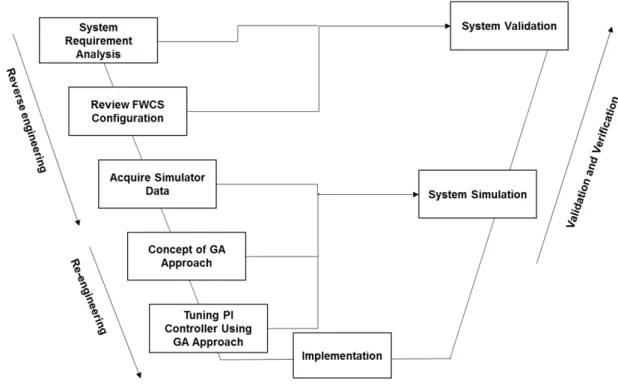
In this paper, a lifecycle with four phases was adopted: reverse, re-engineering, imple- mentation, and validation and verification [3].
Figure 1 shows the entire system development process. In the reverse engineering process, we analysed the system requirements, decom-
[Figure 1] System development process
posed the functions of the FWCS, and acquired the data set of the SG. In the re-engineering process, the Genetic Algorithm (GA) method is described. This approach is used to tune the feedwater PI controller in order to improve performance of this controller. Next, the novel PI controller is tuned during the implementation stage. In the validation and verification process, both the GA-PI controller and the existing controller are simulated in order to compare their performances.
2. Reverse Engineering Process
2.1 System Requirement Analysis
There are several systems such as the Power Control System (PCS) and the Process- Component Control System (P-CCS) in the non-safety control system in the APR 1400.
The PCS consists of the Reactor Regulating System (RRS), the Digital Rod Control System (DRCS), and the Reactor Power Cutback System (RPCS). In addition, the P-CCS encompasses the Nuclear Steam Supply System (NSSS)
Process Control System (NPCS) and Balance of Plant (BOP) control systems. The NPCS includes the FWCS, Steam Bypass Control System (SBCS), Pressurizer Pressure Control System (PPCS), Pressurizer Level Control System (PLCS), and other miscellaneous NSSS control functions.
Figure 2 depicts the structures of the non- safety control systems in the APR 1400 [4].
The FWCS is one of the non-safety control systems. The purpose of this system is the automatic control of the SG downcomer water level at different power reactor levels. The SG level is controlled during the several modes of operation. The first mode is steady-state operation. The second mode consists of power ramping from 5% to 100% at a rate of 1% per minute between 5% and 15%, and a rate of 5%
per minute between 15% and 100%. The third mode consists of power stepping from 5% to 100% at a rate of 1% between 5% and 15%, and a rate of 10% between 15% and 100%.
The fourth state is caused by loss of one of three operating feedwater pumps. Load elimination of any magnitude is the final mode [4].
[Figure 2] Non-safety control systems of APR 1400
2.2 Review of the Feedwater Control System Configuration
Figure 3 illustrates the FWCS scheme [2].
The required feedwater flow is computed as the summed error of the compensated level error, and selected flow error. The compensated level error is the difference between a com- pensated SG downcomer water level signal and the level setpoint. The selected flow error signal is the difference between the steam flow signal and the total feedwater flow signal at the high power level (above 20%). However, at the lower power level (below 20%), the selected flow error sig nal is the difference between the downcomer feedwater flow and calculated steam flow signals.
At the low power level, the compensated level error signal is combined with the selected flow error signal. The economizer feedwater control valve position demand signal is reset to zero, causing the closure of this valve. The pump speed setpoint demand signal is at its
minimum value, hence, the downcomer feedwater control valve regulates the feedwater flow rate.
At the high power level, the compensated level error signal and the selected flow error signal are combined. The flow demand to the downcomer feedwater control valve program is set to an adjustable bias setpoint which positions the downcomer valve to allow approximately 10% of full-power feedwater flow. The economizer feedwater control valve and the main feedwater pump speed determine the feedwater flow rate.
The control structure of the FWCS and the SG is shown in Figure 4.
[Figure 3] Block diagram of the feedwater control
[Figure 4] Overall scheme of the FWCS for output tracking
2.3 Acquisition of the Simulator Input/Output Data at 100% Reactor Power Level In this work, we chose 100% reactor power level as the NPP state at which to acquire data. There are several parameters that affect SG level changes, such as steam flow rate, feedwater flow rate, feedwater temperature, and reactor power. However, the changes of the feedwater flow rate and the steam flow rate have a major impact on the SG secondary water mass [2]. The input to the FWCS is the feedwater flow rate and its output is the steam flow rate. Using the Safety and Performance Analysis Code (SPACE) for Nuclear Power Plants, which is developed by the Korean nuclear industry [5], the input/output data set is obtained through model experiments. This data set was processed by the system identification algorithm [6], [7] to develop the steam generator model, which is shown in equation (1):
Gs ssTr fsTr KsTz
e sTd (1)
where K1 is a constant parameter, Tr and Tz
are time constant parameters, ξ1 is the associated damping constant, and Td is a time delay.
3. Reverse Engineering Process
3.1 Genetic Algorithm Approach
GA is one of the probabilistic optimization approaches [8]. This approach is robust and can handle complicated and global optimization problems. GA begins with an initial population which consists of numerous chromosomes and occurs in the generation. There are a number of iterations when implementing GA, and each
iteration is expressed as a generation. Each chromosome illustrates a solution to the problem, and the objective function evaluates the per- formance of the chromosome in each generation.
In the GA, there are three main stages: Selection, Crossover, and Mutation.
In order to determine the parameters of a system using the GA method, a population with various chromosomes Θ is initiated. The search space is expressed as
ΩΘ = {Θ ∈ ℜm} θ1min ≤ θ1 ≤ θ1max,
θ2min ≤ θ2 ≤ θ2max, (2) …
θm min ≤ θm ≤ θm max
where ℜm is real coordinate space of m dimensions, θi (i = 1 … m) are the chromosomes, that are fostered in the constrained space ΩΘ
during the genetic operations. There are multiple methods that can be used to determine the upper and lower bounds of θi in equation (2). The original chromosome will be unchanged if a chromosome which is created by the operations of the three main stages is outside of the constrained space ΩΘ. The above-mentioned stages are described below:
A. Selection
The GA employs the Roulette Wheel method.
The probability that an individual θi becomes member of the subsequent generation at each random trail is defined in equation (3).
θ
(3)
where f(θi) is the best objective value of the individual θi. After the selection stage, the multiple crossover and mutation stages will be implemented.
B. Multiple Crossover
A multi-crossover approach is proposed [9]. Three chromosomes θ1, θ2, and θ3 are randomly selected from the mating pool and will be crossed with each other. Figure 5 illustrates the proposed multi-crossover process.
As shown in Figure 5, a new adjusted direction is (2θ1 – θ2 – θ3). Additionally, we define c as a random number picked up from [0, 1]. If c
≥ the crossover probability (Pc), then the multiple crossover formulas are shown:
Parents Offspring
θ1 ⟶ θ1 + r(2θ1 – θ2 – θ3) (4) θ2 ⟶ θ2 + r(2θ1 – θ2 – θ3) θ3 ⟶ θ3 + r(2θ1 – θ2 – θ3)
where r is a random value which is identified the crossover score of three chromosomes, r
∈ [1,0]. If c < Pc, there is no crossover operation.
C. Mutation
After the crossover, the mutation is executed to mutate on several chosen chromosomes Θ.
If k ≥ the mutation probability (Pm), then Pm x M chromosomes in the current population are randomly selected to mutate. Where k is a random number, r ∈ [0, 1]. The mutation operation for the chosen Θ is defined as:
Θ ⟵ Θ + sφ (5)
Where s is a positive value and φ is a vector of random noises which generates a perturbation on Θ, and φ ∈ ℜm.
3.2 Tuning the PI controller using the GA approach
In this paper, 100% reactor power level is selected for the design the new PI algorithm.
We want to obtain the optimum parameters Kp, and Ki of the PI controller of the FWCS using the GA. The parameters of the PI controller are the chromosomes and are expressed as:
θi = [Kp Ki]i ∈ ℜm Where i = 1… m (6)
The new PI controller must be more robust and superior than the existing one. Thus, the performance of the FWCS is increased. This leads to stabilize the steam generator water level the mentioned power level.
There are many types of errors such as Integral Squared Error (ISE), Integral Absolute Error (IAE), and Integral Time Weighted Absolute Error (ITAE) which may be applied when utilizing the GA [10]. However, we employed the ITAE criterion to evaluate the objective function.
This is due to the fact that the ITAE is
[Figure 5] Directions of Multi Crossover Chromosomes
suitable for a closed-loop response where overshoot, settling and rise times are the primary performance considerations [8]. The ITAE is defined as:
ITAE (7)
Figure 6 [11] illustrates the feedback control system based on a genetic PI controller. The parameters of the PI controller are tuned through the GA approach. The initial population is produced randomly and employed to compute the objective function of each chromosome in the population.
4. Implementation
There are several steps in the GA approach, which must be performed in order to obtain the parameters of the feedwater PI controller [8].
Step 1: The initial population, which contains M chromosomes is generated. Two chromosomes Kp and Ki are randomly created from the search space Θ.
Step 2: We evaluate the objective function (ITAE) value for each chromosome.
Step 3: The algorithm is terminated when an expected value of the objective function (ITAE) is obtained or the pre-specified number of generations is obtained.
Step 4: If the ITAE value is not satisfactory, reproduction, multiple crossover, and mutation are performed until the desired ITAE value is obtained. The original chromosome is maintained when the outcomes of the chromosome during the operations is out of the search space Θ.
With the help of the optimization application in MATLAB [12], after 27 generations, the objective function value of 0.5 was obtained.
The best value of Kp was computed as 50.5075 and the best value of Ki, 1.2566. Therefore, the transfer function of the PI controller is given by equation (8):
PI (8) 5. Validation and Verification
5.1 System Simulation
Figure 7 illustrates the overall block diagram of the FWCS based on the GA-PI controller which is developed in Simulink/MATLAB [12].
As shown in Figure 7, the pump and valve transfer function is assumed to be a first order transfer function. From the simulation, the step response of the closed-loop system for
[Figure 6] Feedback control system based on genetic PI Controller
[Figure 7] Overall block diagram
the GA-PI controller at 100% reactor power level is obtained and is depicted in Figure 8.
The peak overshoot value is 63.49, and the steady state value is 50.04 when the simulation was run for 200 seconds. Therefore, we are able to calculate the overshoot percentage, approximately 26.89%.
5.2 System validation
In order to demonstrate the improved per- formance of the GA-PI controller, a comparison was made between the step responses of the existing PI feedwater controller and the GA-PI controller at 100% reactor power level. Figure 9 shows the step responses of two mentioned controllers when simulated for 4500 seconds.
Based on Figure 9, the GA PI controller is significantly more stable than the existing controller. Thus, the developed GA PI controller of the FWCS exhibits greater stability than the current PI controller.
6. Conclusion and Future work
The development of a PI controller for the APR 1400 FWCS using a systems engineering
approach is presented in this work. The technical processes which cover the reverse and re-eng- ineering processes, implementation process as well as the validation and verification process are performed. System requirements analyses are undertaken in order to determine the tuning parameters of the feedwater PI controller. In the implementation phase, the GA approach is used to determine the best values of Kp and Ki. The simulation and evaluation of the existing PI and the developed GA-PI controllers of the FWCS is performed in the validation and verification process.
In this study, an attempt is made to reduce the settling time of the system response and increase the speed of the response by designing a controller using the GA technique.
A comparison of the new and existing PI controllers is performed. Through this com- parison, the feedwater controller using GA demonstrates improved stability. The designed controller reduces the percentage overshoot by 25.25%. Further work shall focus on using the GA-PI control strategy in the FWCS for other reactor power levels.
[Figure 8] Step response of the closed-loop system for the GA-PI
[Figure 9] Comparison of the step responses of the closed-loop system for the GA-PI and the existing PI controllers
Acknowledgement
This work was supported by the 2018 Research fund of the KEPCO International Nuclear Graduate School (KINGS).
References
1. KHNP Nuclear Power Education Institute, APR 1400 Control Systems.
2. J. J. Sohn and P. H. Seong , “A steam generator model identification and robust H
∞ controller design with v-gap metric for a feedwater control system,” Annals of Nuclear Energy, vol. 37, pp. 180-195, 2010.
3. A. Kossiakoff, W. N. Sweet, S. J. Seymour and S. M. Biemer, Systems Engineering Principles and Practice, Wiley-Interscience;
2 edition, 2011.
4. “United States Nuclear Regulatory Commission, APR1400 Design Control,” [Online]. Available:
https://www.nrc.gov/. [Accessed 5 11 2018].
5. S. J. Ha, C. E. Park, K. D. Kim and C. H.
Ban, “Development of The Space Code for Nuclear Power Plants,” Nuclear Engineering and Technology, vol. 43, no. 1, pp. 45-62, 2011.
6. L. Ljung, System Identification: Theory for the User, second edition, New Jersey:
Prentice Hall, 1999.
7. L. Ljung, “Identification for Control: Simple Process Models,” Proceedings of the 41st IEEE Conference on Decision and Control, pp. 4652-4657, 2002.
8. B. Naresh, M. Kumar and N. Yadaiah, “GA Based Tuning of PI Controller,” IEEE Recent Advances in Intelligent Computational Systems, pp. 321-325, 2011.
9. S. Tsutsui and D. Goldberg , “Search space boundary extension method in real coded genetic algorithm,” Information Sciences , vol. 133, pp. 229-247, 2001.
10. A. Mirzal, S. Yoshii and M. Furukawa, “PID Parameters Optimization by Using Genetic Algorithm,” ISTECS Journal, vol. 8, pp.
34-43, 2006.
11. L. Fan and E. M. Joo, “Design for Auto- tuning PID Controller Based on Genetic Algorithms,” 4th IEEE Conference on Industrial Electronics and Applications, pp. 1924- 1928, 2009.
12. The Mathworks Inc., 2018a. [Online]. Available:
https://www.mathworks.com. [Accessed 22 10 2018].
![Figure 2 depicts the structures of the non- safety control systems in the APR 1400 [4].](https://thumb-ap.123doks.com/thumbv2/123dokinfo/4815587.523608/3.892.225.669.153.426/figure-depicts-structures-non-safety-control-systems-apr.webp)
![Figure 3 illustrates the FWCS scheme [2].](https://thumb-ap.123doks.com/thumbv2/123dokinfo/4815587.523608/4.892.122.779.147.462/figure-illustrates-fwcs-scheme.webp)
![Figure 6 [11] illustrates the feedback control system based on a genetic PI controller](https://thumb-ap.123doks.com/thumbv2/123dokinfo/4815587.523608/7.892.111.429.136.366/figure-illustrates-feedback-control-based-genetic-pi-controller.webp)
