KIEAE Journal
Korea Institute of Ecological Architecture and Environment 66
1)
Characteristics Analysis of the Heat Exchange Rate according to Soil Temperature and Grout Material using Numerical Simulation
Oh, Jin Hwan*⋅Nam, Yu Jin**
* Dept. of Architecture, Cheongju University, South Korea
** Corresponding author, Dept. of Architecture, Cheongju University, South Korea ([email protected])
A B S T R A C T K Y E W O R D S
The ground source heat pump (GSHP) system has attracted much of attention, because of its stability of heat production and the high efficiency of the system. Performance of the heat exchanger is dependent on the soil temperature, the ground thermal conductivity, the operation schedule, the pipe placement and the design temperature. However, in spite of the many variables of these systems, there have been few research on the effect of the systems on system performance. In this study, analysis of the heat exchange rate according to soil temperature and grout material was conducted by numerical simulation. Furthermore, the heat distribution around the ground heat exchanger was presented on the different conditions of grout and underground temperature by the simulation.
ⓒ 2014 KIEAE Journal
Ground source heat pump, Ground temperature, Grout,
Heat exchange rate, Simulation
A C C E P T A N C E I N F O
Received March 5, 2014
Final revision received March 20, 2014 Accepted March 25, 2014
1. Introduction
The thermal heat pump system is a temperature differential energy technology, utilizing the underground temperature in order to keep the yearly constant temperature and to secure the stable heat source. Because its system coefficient of performance is higher than the existing general air heat pump system, it is expected as a sustainable and greenhouse gas reducing next generation energy technology.
Also, most equipments are installed underground, allowing the buildings with mandatory renewable energy use the flexible exterior design, compared to other renewable energy sources. However, the thermal heat pump system, with its high initial investment cost and the system performance, varies depending on the various conditions,
pISSN 2288-968X, eISSN 2288-9698 http://dx.doi.org/10.12813/kieae.2014.14.2.029
such as the earth condition, underground water, grout material; in order to achieve high system efficiency, there needs to be the appropriate design considering the conditions of the selected site and the comprehensive analysis of the construction cost and system performance.
Especially, the land's heat conductivity and the underground temperature, and the underground water current speed, etc. are the important elements that influence this system. On the other hand, Fig. 1 shows the mean underground water temperature distribution. 1) The under- ground water mean temperature distribution in the central region is about 13℃, and in the south about 15℃, which implies that even in the same system condition, the heat performance varies according to the installed areas.
However, there are few quantitative analysis study data
on such influence, and especially so in the areas of the long
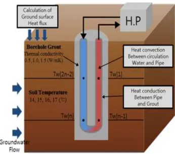
Fig. 2 General heat exchanger
Fig. 1 Distribution of mean groundwater temperatures of Shallow wells (Lee et.al. 2006)
term simulation through the detailed interpretation. For the thermal heat pump system performance analysis as per the underground temperature distribution and the grout material variation, there are many studies domestically and overseas. In the areas of the underground temperature distribution application, Penghui Gao et. al. 2) investigated the underground temperature distribution characteristics including the earthen porosity and the water's rate, utilizing the simulation, and implemented the underground heat exchanger arrangement study; C.O. Popiel et. al. 3) monitored the underground temperature in Poznan City and proposed the appropriate underground heat exchanger at the selected site.
Domestically, Shin Hyun-Jun, et. al. 4) measured the per depth underground temperature distribution and evaluated the thermal energy use potential of the selected site. Also, Fabien Delaleux et. al. 5) and A.A. Alrtimi et. al. 6) compared in analysis the heat conductivity variation according to the grout admixture variation; Roque Borinaga-Trevino et.al. 7) implemented the heat conductivity analysis as per the admixture rate variation through the experiments, to confirm the influence of the revised admixture use on the underground heat exchanger design length. Im Hyo-jae et.
al. 8) measured the heat conductivity of the underground heat exchanger as per the grout material through the
experiments to analyze the influence of the grout material on the heat delivery of the underground heat exchanger.
However, few studies compared and analyzed in detail the performance of the thermal heat pump system through the detailed analysis of the heat transfer between the underground heat exchanger and the circulating water and soil as per the earthen condition and the grout material.
In order to predict the underground heat correctly, we need to interpret correctly the circulating water within the heat exchanger, and the convection heat delivery within the pipe interior walls, and the heat transfer between the pipe and the grout and soil. Fig. 2 shows the heat transfer concept drawings around the underground heat exchanger.
The domestic underground heat exchanger materials are generalized for considering the design condition, but the variables as per the regional climate and the underground temperature have to be considered in the system design.
In this study in order to optimize the underground heat exchanger design, we reviewed the underground heat variation as per the initial underground temperature and grout material variation, utilizing the underground heat prediction simulation developed in the previous study.
Through the interpretation result, we analyzed the
relationship between the underground temperature and the
underground heat of the place from which the system was
introduced from. The study is intended to be used as a
basic data for the feasibility decision in selecting the grout
material.
2. Study method
2.1. Simulation summary
In the underground heat exchanger design, in order to find the optimum design method, we need to review the various variables such as geotechnical condition of the selected site. Also, we have to determine what materials will be used as well, in considering the grout material characteristics. In this study in order to interpret precisely underground heat exchanger and with the soil heat exchange, and underground heat exchanger and the circulating water's heat exchange, 3-dimensional underground heat /underground water transfer simulation method developed in the previous study 9) was used as a tool combined with the underground heat exchanger model and the earth surface heat resin model. For the circulating water model within the underground heat exchanger, the interpretation model was used with phase 1 convection expansion formula was dioxided. Also, German WASY company's FEFLOW based on the finite-element method (FEM) was used for the underground water and underground heat move's interpretation code.
Regarding the interpretation method and soil's heat material property estimation method, the methods implemented in the previous study 10) was used in reference. The solid state thermal conductivity of the soil was calculated, using the weighted geometric mean method of each element in solid state thermal conductivity and the mixing rate, as in formula (1).
·
(1)
Here, and are each the elements A, B's thermal conductivity, m and n are each the elements A, B's volume rates. Also, the heat capacity is calculated as per the soil particle's specific heat and density.
(2)
is heat capacity, is material's own specific heat, is material's own density, is the volume rate when =1. In this review, thermal conductivity of the mean of the solid
part and the opening part was calculated according to the liquid parallel model, including the solid part and the opening part. On the other hand, the underground heat exchanger model was based on the one-dimensional 이류 expansion equation, calculating the heat exchanger pipe inner walls and circulating water's heat exchange quantity, and implemented the abnormal calculation of calculating the Circulating Water temperature at each points and the underground releasing heat current quantity. Formula (3) shows the Circulating Water model's formula used in this interpretation model.