Copyright ⓒ The Korean Society for Aeronautical & Space Sciences Received: July 29, 2016 Revised: October 9, 2017 Accepted: December 14, 2017
623
http://ijass.org pISSN: 2093-274x eISSN: 2093-2480Paper
Int’l J. of Aeronautical & Space Sci. 18(4), 623–640 (2017) DOI: http://dx.doi.org/10.5139/IJASS.2017.18.4.623
Design and Analysis of High-Speed Unmanned Aerial Vehicle Ground
Directional Rectifying Control System
Qiaozhi Yin*, Hong Nie**, Xiaohui Wei***, and Kui Xu*
State Key Laboratory of Mechanics and Control of Mechanical Structures, College of Aerospace Engineering, Nanjing University of Aeronautics and Astronautics, Nanjing 210016, China
Abstract
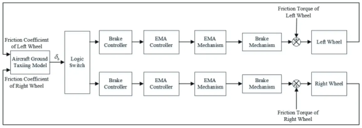
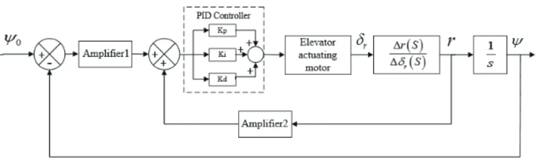
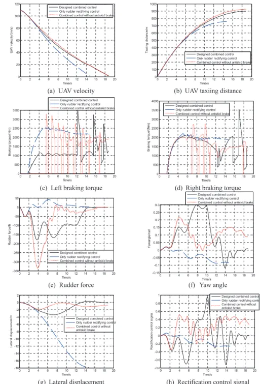
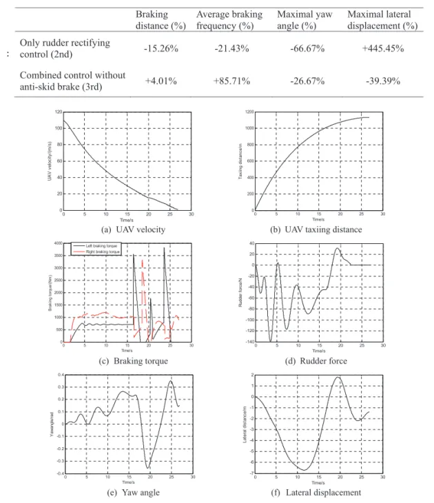
The full nonlinear equations of an unmanned aerial vehicle ground taxiing mathematical dynamic model are built based on a type of unmanned aerial vehicle data in LMS Virtual.Lab Motion. The flexible landing gear model is considered to make the aircraft ground motion more accurate. The electric braking control system is established in MATLAB/Simulink and the experiment of it verifies that the electric braking model with the pressure sensor is fitted well with the actual braking mechanism and it ensures the braking response speediness. The direction rectification control law combining the differential brake and the rudder with 30% anti-skid brake is built to improve the directional stability. Two other rectifying control laws are demonstrated to compare with the designed control law to verify that the designed control is of high directional stability and high braking efficiency. The lateral displacement increases by 445.45% with poor rectification performance under the only rudder rectifying control relative to the designed control law. The braking distance rises by 36m and the braking frequency increases by 85.71% under the control law without anti-skid brake. Different landing conditions are simulated to verify the good robustness of the designed rectifying control.
Key words: High-speed UAV, Rectifying control, Electric brake, Co-simulation
1. Introduction
High-speed unmanned aerial vehicles (UAVs) are growing in popularity among a large variety of fields in recent years due to their low cost and flexibility in practice [1]. The taxiing process of a high-speed UAV on the ground is an important stage during the whole flight. The direction control and stability has great influence on the safety and reusability of a UAV. The requirements of high precision control, strong robustness and quick response of control systems all bring challenges to brake and direction rectification control systems of a high-speed UAV [2]. This is the focus of the present study. With the development of the ‘more electric’ concept [3], applying fly-by-wire technique instead of hydraulic system to the braking control system of a high-speed UAV has many advantages on security, weight, reliability and accuracy [4]. In addition, it will also improve the direction control stability
with a well-designed direction rectification control law. The aircraft is easy to yaw resulting from the factors including the asymmetry of the aircraft construction, the rough runway and the cross wind [5]. If the lateral offset distance and yaw angle are not corrected in time especially when a UAV is running at a high speed on the ground, the aircraft will even veer off the runway, causing severe accidents. In terms of the aircraft dynamics modeling, Hanke [6] puts emphasis on the dynamic modeling of Boeing-747 in the air in a NASA report. Barnes A.G. [7] establishes the 6 degree-of-freedoms (DOFs) aircraft taxiing mathematical model and analyzes the kinetic characteristic with the numerical simulation method. Yoon [8] builds the nonlinear 6-DOF dynamics model of the automatic landing aircraft during the landing phase. Reinhard [9] builds the flexible aircraft dynamic model using SIMPACK to study the dynamic response in the conditions of landing and anti-skid braking. Ro [10] presents the theoretical derivation of
This is an Open Access article distributed under the terms of the Creative Com-mons Attribution Non-Commercial License (http://creativecomCom-mons.org/licenses/by- (http://creativecommons.org/licenses/by-nc/3.0/) which permits unrestricted non-commercial use, distribution, and reproduc-tion in any medium, provided the original work is properly cited.
* Ph. D Student
** Professor, Corresponding author: [email protected]
*** Professor
DOI: http://dx.doi.org/10.5139/IJASS.2017.18.4.623
624
Int’l J. of Aeronautical & Space Sci. 18(4), 623–640 (2017)
equations of motion of the landing gear system to study the aircraft motion on the ground. Zhang [11] builds the aircraft dynamic model in a dynamic software MSC.ADAMS and studies the aircraft performance during asymmetric landing, hydraulic braking and nose wheel steering process. Comparing to the previous works on aircraft dynamic modeling techniques, an advanced co-simulation method is used in this study to build a more accurate UAV ground rollout model. A virtual prototype of the high-speed UAV is built in a multibody system dynamics software LMS Virtual. Lab Motion. Not only the flexibility of the landing gears is considered, but all the forces on the UAV when taxiing on the runway are simulated. However, a dynamics software usually only has a simple control toolbox. Therefore, the complicated control systems in this study are established in MATLAB/Simulink. The data obtained in these two softwares are transferred to each other in every sampling interval till the simulation process ends.
In terms of the direction control research, Zhang [12] establishes the aircraft dynamic model in MATLAB/Simulink and carries out the simulation of the aircraft differential brake. Yan [13] adopts the lateral control law combining lateral deviation and velocity to correct the direction of a UAV. Deng [14] sets up the ground taxiing system for a UAV with four wheels and analyzes the direction rectification performance of the differential braking system and the nose wheel steering system. Li [15] adopts the differential brake based on the optimal slip-rate braking system to correct the aircraft direction and studies the property of rectifying deviation under the condition of 70m/s landing velocity with cross wind. Wang [16] puts forward a direction rectification control method combining differential brake with rudder to correct a UAV direction under the step crosswind during the whole taxiing process. After successful use of the direction control laws, the analysis is extended to design a combined direction control law for a high-speed UAV in this study. The allocation for the gains of the control algorithm is designed to ensure both the direction rectification and the braking efficiency. Also, studies [11, 17] have shown that sensors have great impact on the hydraulic braking control systems. Thus in this paper, the models of the sensors are added in the electric control system to increase the fidelity of the simulation.
In terms of the electric brake study, Goodrich [18] applies electric braking system on ‘Global Hawk’ in 2005. In 2014, Lin [19] introduces the low voltage brake drive controller designed by digital signal processor + complex programmable logic device (DSP+CPLD) and accomplishes the dual redundancy design of electric braking system to improve the braking performance and efficiency. Wei [20]
designs a new fuzzy-proportional-integral-derivative (PID) anti-skid braking control law on an electric braking system and verifies the braking stability under this braking system. Based on the previous researches of the electric brake, the electric brake mechanism is designed and the experiment is carried out to verify the speediness and reliability in this study.
The purpose of this study is to design a combined direction control law and to analyze the ground maneuvers of a high-speed electric UAV. In Sec. 2, the full variable nonlinear UAV ground taxiing mathematical dynamic model is built in LMS Virtual.Lab Motion, including the aerodynamic force, the rudder force, the elevator force, the drag parachute, the flexible landing gear and the tire force. Then in Sec. 3, the electric anti-skid braking control system is established in MATLAB/Simulink. The test of the electric brake mechanism is conducted to verify the accuracy of the braking system model. In Sec. 4, the rectification control law combining the differential brake and the rudder is designed and the gains of the algorithm are allocated to improve the directional stability. In Sec. 5, different conditions of the UAV are simulated to verify the designed rectifying control law. Finally in Sec. 6, the conclusion of this study is given.
2. Aircraft ground taxiing dynamic modeling
The coordinate systems adopted in this study include: the ground axis system (Sg-OgXgYgZg), the body axis system (Sb-ObXbYbZb), the velocity axis system (Sa-OaXaYaZa) and the stability axis system (Ss-OsXsYsZs). The definition of each coordinate system can be found in reference [21].When the UAV is taxiing on the ground, the forces on the UAV include: gravity, aerodynamic force (including lift, drag, side force), drag parachute, elevator force, rudder force, ground reaction force, side force and friction force on the tires, and the torques produced by the forces above. The force analysis of the UAV movement on the ground is shown in Fig. 1. All the parameters of the UAV and the control systems are shown in Appendix A.
2.1 Tire Model
The tires are the important components of an aircraft during the landing, take-off and rollout processes on the ground. They can not only bear the ground reaction force, friction force and lateral force, but also can play an important role in energy absorption.
In the ground axis system, the ground reaction force
4
maneuvers of a high-speed electric UAV. In Sec. 2, the full variable nonlinear UAV ground taxiing mathematical dynamic model is built in LMS Virtual.Lab Motion, including the aerodynamic force, the rudder force, the elevator force, the drag parachute, the flexible landing gear and the tire force. Then in Sec. 3, the electric anti-skid braking control system is established in MATLAB/Simulink. The test of the electric brake mechanism is conducted to verify the accuracy of the braking system model. In Sec. 4, the rectification control law combining the differential brake and the rudder is designed and the gains of the algorithm are allocated to improve the directional stability. In Sec. 5, different conditions of the UAV are simulated to verify the designed rectifying control law. Finally in Sec. 6, the conclusion of this study is given.
2. Aircraft ground taxiing dynamic modeling
The coordinate systems adopted in this study include: the ground axis system (SgO X Y Zg g g g), the
body axis system (S O X Y Zb b b b b), the velocity axis system (S O X Y Za a a a a) and the stability axis system
(S O X Y Zs s s s s). The definition of each coordinate system can be found in reference [21].
When the UAV is taxiing on the ground, the forces on the UAV include: gravity, aerodynamic force (including lift, drag, side force), drag parachute, elevator force, rudder force, ground reaction force, side force and friction force on the tires, and the torques produced by the forces above. The force analysis of the UAV movement on the ground is shown in Fig. 1. All the parameters of the UAV and the control systems are shown in Appendix A.
2.1 Tire Model
The tires are the important components of an aircraft during the landing, take-off and rollout processes on the ground. They can not only bear the ground reaction force, friction force and lateral force, but also can play an important role in energy absorption.
In the ground axis system, the ground reaction force P to the aircraft is:
0 0 ( ) ,
T T
x y z n ml mr
PP P P P P P (1)
to the aircraft is:
625
Qiaozhi Yin Design and Analysis of High-Speed Unmanned Aerial Vehicle Ground Directional Rectifying Control System
http://ijass.org 4
maneuvers of a high-speed electric UAV. In Sec. 2, the full variable nonlinear UAV ground taxiing mathematical dynamic model is built in LMS Virtual.Lab Motion, including the aerodynamic force, the rudder force, the elevator force, the drag parachute, the flexible landing gear and the tire force. Then in Sec. 3, the electric anti-skid braking control system is established in MATLAB/Simulink. The test of the electric brake mechanism is conducted to verify the accuracy of the braking system model. In Sec. 4, the rectification control law combining the differential brake and the rudder is designed and the gains of the algorithm are allocated to improve the directional stability. In Sec. 5, different conditions of the UAV are simulated to verify the designed rectifying control law. Finally in Sec. 6, the conclusion of this study is given.
2. Aircraft ground taxiing dynamic modeling
The coordinate systems adopted in this study include: the ground axis system (SgO X Y Zg g g g), the body axis system (S O X Y Zb b b b b), the velocity axis system (SaO X Y Za a a a) and the stability axis system
(S O X Y Zs s s s s). The definition of each coordinate system can be found in reference [21].
When the UAV is taxiing on the ground, the forces on the UAV include: gravity, aerodynamic force (including lift, drag, side force), drag parachute, elevator force, rudder force, ground reaction force, side force and friction force on the tires, and the torques produced by the forces above. The force analysis of the UAV movement on the ground is shown in Fig. 1. All the parameters of the UAV and the control systems are shown in Appendix A.
2.1 Tire Model
The tires are the important components of an aircraft during the landing, take-off and rollout processes on the ground. They can not only bear the ground reaction force, friction force and lateral force, but also can play an important role in energy absorption.
In the ground axis system, the ground reaction force P to the aircraft is:
0 0 ( ) ,
T T
x y z n ml mr
PP P P P P P (1) (1) where Pn, Pml, Pmr are the ground reaction forces to the nose
tire, the left and the right main tires respectively. In the body axis system, the ground reaction torque
5
where P ,n P ,ml P are the ground reaction forces to the nose tire, the left and the right main tires mr respectively. In the body axis system, the ground reaction torque MP
is: ( ) / 2 ( ) , 0 Px ml mr w P Py n n ml mr m Pz M P P b M M P a P P a M (2)
where b is the distance between the two main wheels. w a is the distance between the nose wheel and n the gravity center of the aircraft. a is the distance between the main wheels and the gravity center of m the aircraft. The rotational speed of a braking wheel is under the influence of the ground friction force fx and the braking torque M :b
, x g b r J f R M (3) , r g v R (4)
where is the rotational speed, is the angular acceleration, J is the wheel moment of inertia, r vr is the tire linear speed, Rg is the rolling radius. Slip rate is defined as the slip degree of the tire during
the braking process. The expression is given by: , x r x v v v (5)
where is the slip rate of a braking wheel, v is the UAV taxiing speed. The friction coefficient x of the braking tire on different runways are related to the slip rate of the tire [22]:
1 1
0.8sin(1.5344tan (14.0326 )), Dry runway, 0.4sin(2.0192tan (8.2098 )), Wet runway.
μ = σ
μ = σ
(6)
The friction coefficients of the nose gear and the left and the right main gears are defined as n, ml, mr respectively. Then the friction forces of the tires are:
, , ,
xn n n xml ml ml xmr mr mr
f P f P f P (7)
where P P P and n, ,ml mr f fxn, xml,f are the ground reaction force and the friction force to the nose tire, xmr the left and the right main tires respectively. When the aircraft is yawing, an angle between the driving
is:
5
where P ,n P ,ml P are the ground reaction forces to the nose tire, the left and the right main tires mr respectively. In the body axis system, the ground reaction torque MP
is: ( ) / 2 ( ) , 0 Px ml mr w P Py n n ml mr m Pz M P P b M M P a P P a M (2)
where b is the distance between the two main wheels. w a is the distance between the nose wheel and n the gravity center of the aircraft. a is the distance between the main wheels and the gravity center of m the aircraft. The rotational speed of a braking wheel is under the influence of the ground friction force fx and the braking torque M :b
, x g b r J f R M (3) , r g v R (4)
where is the rotational speed, is the angular acceleration, J is the wheel moment of inertia, r vr
is the tire linear speed, Rg is the rolling radius. Slip rate is defined as the slip degree of the tire during
the braking process. The expression is given by: , x r x v v v (5)
where is the slip rate of a braking wheel, v is the UAV taxiing speed. The friction coefficient x of the braking tire on different runways are related to the slip rate of the tire [22]:
1 1
0.8sin(1.5344tan (14.0326 )), Dry runway, 0.4sin(2.0192tan (8.2098 )), Wet runway.
μ = σ
μ = σ
(6)
The friction coefficients of the nose gear and the left and the right main gears are defined as n, ml, mr respectively. Then the friction forces of the tires are:
, , ,
xn n n xml ml ml xmr mr mr
f P f P f P (7)
where P P P and n, ,ml mr f fxn, xml,f are the ground reaction force and the friction force to the nose tire, xmr the left and the right main tires respectively. When the aircraft is yawing, an angle between the driving
,
(2)
where bw is the distance between the two main wheels. an is the distance between the nose wheel and the gravity center of the aircraft. am is the distance between the main wheels and the gravity center of the aircraft. The rotational speed of a braking wheel is under the influence of the ground friction force fx and the braking torque Mb:
5
where P ,n P ,ml P are the ground reaction forces to the nose tire, the left and the right main tires mr respectively. In the body axis system, the ground reaction torque MP
is: ( ) / 2 ( ) , 0 Px ml mr w P Py n n ml mr m Pz M P P b M M P a P P a M (2)
where b is the distance between the two main wheels. w a is the distance between the nose wheel and n the gravity center of the aircraft. a is the distance between the main wheels and the gravity center of m the aircraft. The rotational speed of a braking wheel is under the influence of the ground friction force fx and the braking torque M :b
, x g b r J f R M (3) , r g v R (4)
where is the rotational speed, is the angular acceleration, J is the wheel moment of inertia, r vr
is the tire linear speed, Rg is the rolling radius. Slip rate is defined as the slip degree of the tire during
the braking process. The expression is given by: , x r x v v v (5)
where is the slip rate of a braking wheel, v is the UAV taxiing speed. The friction coefficient x of the braking tire on different runways are related to the slip rate of the tire [22]:
1 1
0.8sin(1.5344tan (14.0326 )), Dry runway, 0.4sin(2.0192tan (8.2098 )), Wet runway.
μ = σ
μ = σ
(6)
The friction coefficients of the nose gear and the left and the right main gears are defined as n, ml, mr respectively. Then the friction forces of the tires are:
, , ,
xn n n xml ml ml xmr mr mr
f P f P f P (7)
where P P P and n, ,ml mr f fxn, xml,f are the ground reaction force and the friction force to the nose tire, xmr the left and the right main tires respectively. When the aircraft is yawing, an angle between the driving
, (3)
5
where P ,n P ,ml P are the ground reaction forces to the nose tire, the left and the right main tires mr respectively. In the body axis system, the ground reaction torque MP is:
( ) / 2 ( ) , 0 Px ml mr w P Py n n ml mr m Pz M P P b M M P a P P a M (2) where b is the distance between the two main wheels. w a is the distance between the nose wheel and n the gravity center of the aircraft. a is the distance between the main wheels and the gravity center of m the aircraft. The rotational speed of a braking wheel is under the influence of the ground friction force f x and the braking torque M : b
, x g b r J f R M (3) , r g v R (4)
where is the rotational speed, is the angular acceleration, J is the wheel moment of inertia, r v r is the tire linear speed, Rg is the rolling radius. Slip rate is defined as the slip degree of the tire during the braking process. The expression is given by:
, x r x v v v (5)
where is the slip rate of a braking wheel, v is the UAV taxiing speed. The friction coefficient x of the braking tire on different runways are related to the slip rate of the tire [22]:
1 1
0.8sin(1.5344tan (14.0326 )), Dry runway, 0.4sin(2.0192tan (8.2098 )), Wet runway.
μ = σ
μ = σ
(6)
The friction coefficients of the nose gear and the left and the right main gears are defined as n, ml, mr respectively. Then the friction forces of the tires are:
, , ,
xn n n xml ml ml xmr mr mr
f P f P f P (7)
where , ,P P P and n ml mr f fxn, xml,f are the ground reaction force and the friction force to the nose tire, xmr the left and the right main tires respectively. When the aircraft is yawing, an angle between the driving
, (4)
where ω is the rotational speed,
5
where P ,n P ,ml P are the ground reaction forces to the nose tire, the left and the right main tires mr respectively. In the body axis system, the ground reaction torque MP
is: ( ) / 2 ( ) , 0 Px ml mr w P Py n n ml mr m Pz M P P b M M P a P P a M (2)
where b is the distance between the two main wheels. w a is the distance between the nose wheel and n the gravity center of the aircraft. a is the distance between the main wheels and the gravity center of m the aircraft. The rotational speed of a braking wheel is under the influence of the ground friction force fx and the braking torque M :b
, x g b r J f R M (3) , r g v R (4)
where is the rotational speed, is the angular acceleration, J is the wheel moment of inertia, r vr is the tire linear speed, Rg is the rolling radius. Slip rate is defined as the slip degree of the tire during
the braking process. The expression is given by: , x r x v v v (5)
where is the slip rate of a braking wheel, v is the UAV taxiing speed. The friction coefficient x of the braking tire on different runways are related to the slip rate of the tire [22]:
1 1
0.8sin(1.5344tan (14.0326 )), Dry runway, 0.4sin(2.0192tan (8.2098 )), Wet runway.
μ = σ
μ = σ
(6)
The friction coefficients of the nose gear and the left and the right main gears are defined as n, ml, mr respectively. Then the friction forces of the tires are:
, , ,
xn n n xml ml ml xmr mr mr
f P f P f P (7)
where P P P and n, ,ml mr f fxn, xml,f are the ground reaction force and the friction force to the nose tire, xmr the left and the right main tires respectively. When the aircraft is yawing, an angle between the driving
is the angular acceleration,
Jr is the wheel moment of inertia, vr is the tire linear speed, Rg is the rolling radius. Slip rate is defined as the slip degree of the tire during the braking process. The expression is given by:
5
where P ,n P ,ml P are the ground reaction forces to the nose tire, the left and the right main tires mr respectively. In the body axis system, the ground reaction torque MP is:
( ) / 2 ( ) , 0 Px ml mr w P Py n n ml mr m Pz M P P b M M P a P P a M (2) where b is the distance between the two main wheels. w a is the distance between the nose wheel and n the gravity center of the aircraft. a is the distance between the main wheels and the gravity center of m the aircraft. The rotational speed of a braking wheel is under the influence of the ground friction force f x and the braking torque M : b
, x g b r J f R M (3) , r g v R (4)
where is the rotational speed, is the angular acceleration, J is the wheel moment of inertia, r v r is the tire linear speed, Rg is the rolling radius. Slip rate is defined as the slip degree of the tire during the braking process. The expression is given by:
, x r x v v v (5)
where is the slip rate of a braking wheel, v is the UAV taxiing speed. The friction coefficient x of the braking tire on different runways are related to the slip rate of the tire [22]:
1 1
0.8sin(1.5344tan (14.0326 )), Dry runway, 0.4sin(2.0192tan (8.2098 )), Wet runway.
μ = σ
μ = σ
(6)
The friction coefficients of the nose gear and the left and the right main gears are defined as n, ml, mr respectively. Then the friction forces of the tires are:
, , ,
xn n n xml ml ml xmr mr mr
f P f P f P (7)
where , ,P P P and n ml mr f fxn, xml,f are the ground reaction force and the friction force to the nose tire, xmr the left and the right main tires respectively. When the aircraft is yawing, an angle between the driving
, (5)
where σ is the slip rate of a braking wheel, vx is the UAV taxiing speed. The friction coefficient μ of the braking tire on
different runways are related to the slip rate of the tire [22]:
5
where P ,n P ,ml P are the ground reaction forces to the nose tire, the left and the right main tires mr respectively. In the body axis system, the ground reaction torque MP is:
( ) / 2 ( ) , 0 Px ml mr w P Py n n ml mr m Pz M P P b M M P a P P a M (2) where b is the distance between the two main wheels. w a is the distance between the nose wheel and n the gravity center of the aircraft. a is the distance between the main wheels and the gravity center of m the aircraft. The rotational speed of a braking wheel is under the influence of the ground friction force f x and the braking torque M : b
, x g b r J f R M (3) , r g v R (4)
where is the rotational speed, is the angular acceleration, J is the wheel moment of inertia, r v r is the tire linear speed, Rg is the rolling radius. Slip rate is defined as the slip degree of the tire during the braking process. The expression is given by:
, x r x v v v (5)
where is the slip rate of a braking wheel, v is the UAV taxiing speed. The friction coefficient x of the braking tire on different runways are related to the slip rate of the tire [22]:
1 1
0.8sin(1.5344tan (14.0326 )), Dry runway, 0.4sin(2.0192tan (8.2098 )), Wet runway.
μ = σ
μ = σ
(6)
The friction coefficients of the nose gear and the left and the right main gears are defined as n, ml, mr respectively. Then the friction forces of the tires are:
, , ,
xn n n xml ml ml xmr mr mr
f P f P f P (7)
where , ,P P P and n ml mr f fxn, xml,f are the ground reaction force and the friction force to the nose tire, xmr the left and the right main tires respectively. When the aircraft is yawing, an angle between the driving
(6) The friction coefficients of the nose gear and the left and the right main gears are defined as μn, μml, μmr respectively. Then the friction forces of the tires are:
5
where P ,n P ,ml P are the ground reaction forces to the nose tire, the left and the right main tires mr respectively. In the body axis system, the ground reaction torque MP is:
( ) / 2 ( ) , 0 Px ml mr w P Py n n ml mr m Pz M P P b M M P a P P a M (2) where b is the distance between the two main wheels. w a is the distance between the nose wheel and n the gravity center of the aircraft. a is the distance between the main wheels and the gravity center of m the aircraft. The rotational speed of a braking wheel is under the influence of the ground friction force f x and the braking torque M : b
, x g b r J f R M (3) , r g v R (4)
where is the rotational speed, is the angular acceleration, J is the wheel moment of inertia, r v r is the tire linear speed, Rg is the rolling radius. Slip rate is defined as the slip degree of the tire during the braking process. The expression is given by:
, x r x v v v (5)
where is the slip rate of a braking wheel, v is the UAV taxiing speed. The friction coefficient x of the braking tire on different runways are related to the slip rate of the tire [22]:
1 1
0.8sin(1.5344tan (14.0326 )), Dry runway, 0.4sin(2.0192tan (8.2098 )), Wet runway.
μ = σ
μ = σ
(6)
The friction coefficients of the nose gear and the left and the right main gears are defined as n, ml, mr respectively. Then the friction forces of the tires are:
, , ,
xn n n xml ml ml xmr mr mr
f P f P f P (7)
where , ,P P P and n ml mr f fxn, xml,f are the ground reaction force and the friction force to the nose tire, xmr the left and the right main tires respectively. When the aircraft is yawing, an angle between the driving
, (7)
where Pn, Pml, Pmr and fxn, fxml , fxmr are the ground reaction force and the friction force to the nose tire, the left and the right main tires respectively. When the aircraft is yawing, an angle between the driving direction and the central plane of the tire is called sideslip angle [23] shown in Fig. 1. In the stability axis system, the sideslip angles of the left and the right main tires are:
6
direction and the central plane of the tire is called sideslip angle [23] shown in Fig. 1. In the stability axis system, the sideslip angles of the left and the right main tires are:
1 tan ( ), / 2 sy m ml sx w v r a v r b (8) and 1 tan ( ), / 2 sy m mr sx w v r a v r b (9)
The deflection angle of the nose tire is l and the sideslip angle of the nose tire is: 1 tan ( sy m). n l sx v r a v (10) The lateral forces of the nose tire and the left and the right tires are:
, , ,
yml ml ml ymr mr mr yn n n
f K f K f K (11)
where
n, ml, mr are sideslip angles of the three tires, v v v aircraft velocity components in sx, ,sy sz s s s s sS O X Y Z , an,am are the distance between the nose wheel, the main wheels and the gravity center
of the aircraft, bw is the distance between the two main wheels, r is the yawing angular velocity,
, ,
n ml mr
K K K are the cornering stiffness of the nose gear and the left and the right gears. Therefore, in
the stability axis system, the resultant force of the lateral force and the friction force on the tire is:
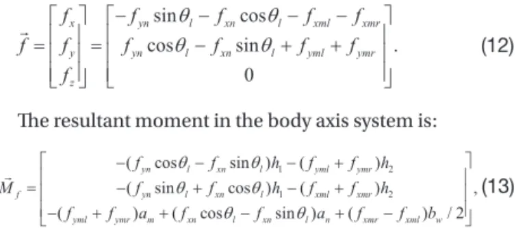
sin cos cos sin . 0 x yn l xn l xml xmr y yn l xn l yml ymr z f f f f f f f f f f f f (12) The resultant moment in the body axis system is:
1 2 1 2 ( cos sin ) ( ) ( sin cos ) ( ) , ( ) ( cos sin ) ( ) / 2 yn l xn l yml ymr f yn l xn l xml xmr yml ymr m xn l xn l n xmr xml w f f h f f h M f f h f f h f f a f f a f f b (13) where h1 and h2 are the distances between the nose wheel, the main wheels and the aircraft horizontal
baseline, respectively.
(8) and
6
direction and the central plane of the tire is called sideslip angle [23] shown in Fig. 1. In the stability axis system, the sideslip angles of the left and the right main tires are:
1 tan ( ), / 2 sy m ml sx w v r a v r b (8) and 1 tan ( ), / 2 sy m mr sx w v r a v r b (9)
The deflection angle of the nose tire is l and the sideslip angle of the nose tire is: 1 tan ( sy m). n l sx v r a v (10) The lateral forces of the nose tire and the left and the right tires are:
, , ,
yml ml ml ymr mr mr yn n n
f K f K f K (11)
where
n, ml, mr are sideslip angles of the three tires, v v v aircraft velocity components in sx, ,sy sz s s s s sS O X Y Z , an,am are the distance between the nose wheel, the main wheels and the gravity center
of the aircraft, bw is the distance between the two main wheels, r is the yawing angular velocity,
, ,
n ml mr
K K K are the cornering stiffness of the nose gear and the left and the right gears. Therefore, in
the stability axis system, the resultant force of the lateral force and the friction force on the tire is:
sin cos cos sin . 0 x yn l xn l xml xmr y yn l xn l yml ymr z f f f f f f f f f f f f (12) The resultant moment in the body axis system is:
1 2 1 2 ( cos sin ) ( ) ( sin cos ) ( ) , ( ) ( cos sin ) ( ) / 2 yn l xn l yml ymr f yn l xn l xml xmr yml ymr m xn l xn l n xmr xml w f f h f f h M f f h f f h f f a f f a f f b (13) where h1 and h2 are the distances between the nose wheel, the main wheels and the aircraft horizontal
baseline, respectively.
(9) The deflection angle of the nose tire is θ1 and the sideslip
angle of the nose tire is:
6
direction and the central plane of the tire is called sideslip angle [23] shown in Fig. 1. In the stability axis system, the sideslip angles of the left and the right main tires are:
1 tan ( ), / 2 sy m ml sx w v r a v r b (8) and 1 tan ( ), / 2 sy m mr sx w v r a v r b (9)
The deflection angle of the nose tire is l and the sideslip angle of the nose tire is: 1 tan ( sy m). n l sx v r a v (10) The lateral forces of the nose tire and the left and the right tires are:
, , ,
yml ml ml ymr mr mr yn n n
f K f K f K (11)
where
n, ml, mr are sideslip angles of the three tires, v v v aircraft velocity components in sx, ,sy sz s s s s sS O X Y Z , an,am are the distance between the nose wheel, the main wheels and the gravity center
of the aircraft, bw is the distance between the two main wheels, r is the yawing angular velocity,
, ,
n ml mr
K K K are the cornering stiffness of the nose gear and the left and the right gears. Therefore, in
the stability axis system, the resultant force of the lateral force and the friction force on the tire is:
sin cos cos sin . 0 x yn l xn l xml xmr y yn l xn l yml ymr z f f f f f f f f f f f f (12) The resultant moment in the body axis system is:
1 2 1 2 ( cos sin ) ( ) ( sin cos ) ( ) , ( ) ( cos sin ) ( ) / 2 yn l xn l yml ymr f yn l xn l xml xmr yml ymr m xn l xn l n xmr xml w f f h f f h M f f h f f h f f a f f a f f b (13) where h1 and h2 are the distances between the nose wheel, the main wheels and the aircraft horizontal
baseline, respectively.
(10) The lateral forces of the nose tire and the left and the right tires are:
31
(a) Front view (b) Top view
Fig. 1. Force analysis of UAV movement on the ground
(a) Front view (b) Top view Fig. 1. Force analysis of UAV movement on the ground
.
DOI: http://dx.doi.org/10.5139/IJASS.2017.18.4.623
626
Int’l J. of Aeronautical & Space Sci. 18(4), 623–640 (2017)
6
direction and the central plane of the tire is called sideslip angle [23] shown in Fig. 1. In the stability axis system, the sideslip angles of the left and the right main tires are:
1 tan ( ), / 2 sy m ml sx w v r a v r b (8) and 1 tan ( sy m/ 2), mr sx w v r a v r b (9)
The deflection angle of the nose tire is l and the sideslip angle of the nose tire is: 1 tan ( sy m). n l sx v r a v (10) The lateral forces of the nose tire and the left and the right tires are:
, , ,
yml ml ml ymr mr mr yn n n
f K f K f K (11)
where
n, ml, mr are sideslip angles of the three tires, v v v aircraft velocity components in sx, ,sy sz s s s s sS O X Y Z , an,am are the distance between the nose wheel, the main wheels and the gravity center
of the aircraft, bw is the distance between the two main wheels, r is the yawing angular velocity,
, ,
n ml mr
K K K are the cornering stiffness of the nose gear and the left and the right gears. Therefore, in
the stability axis system, the resultant force of the lateral force and the friction force on the tire is:
sin cos cos sin . 0 x yn l xn l xml xmr y yn l xn l yml ymr z f f f f f f f f f f f f (12) The resultant moment in the body axis system is:
1 2 1 2 ( cos sin ) ( ) ( sin cos ) ( ) , ( ) ( cos sin ) ( ) / 2 yn l xn l yml ymr f yn l xn l xml xmr yml ymr m xn l xn l n xmr xml w f f h f f h M f f h f f h f f a f f a f f b (13) where h1 and h2 are the distances between the nose wheel, the main wheels and the aircraft horizontal
baseline, respectively.
, (11)
where βn, βml, βmr are sideslip angles of the three tires, vsx, vsy,
vsz aircraft velocity components in Ss-OsXsYsZs, an, am are the distance between the nose wheel, the main wheels and the gravity center of the aircraft, bw is the distance between the two main wheels, r is the yawing angular velocity, Kβn, Kβml,
Kβmr are the cornering stiffness of the nose gear and the left and the right gears. Therefore, in the stability axis system, the resultant force of the lateral force and the friction force on the tire is:
6
direction and the central plane of the tire is called sideslip angle [23] shown in Fig. 1. In the stability axis system, the sideslip angles of the left and the right main tires are:
1 tan ( ), / 2 sy m ml sx w v r a v r b (8) and 1 tan ( ), / 2 sy m mr sx w v r a v r b (9)
The deflection angle of the nose tire is l and the sideslip angle of the nose tire is: 1 tan ( sy m). n l sx v r a v (10) The lateral forces of the nose tire and the left and the right tires are:
, , ,
yml ml ml ymr mr mr yn n n
f K f K f K (11)
where
n, ml, mr are sideslip angles of the three tires, , ,v v v aircraft velocity components in sx sy sz s s s s sS O X Y Z , an,am are the distance between the nose wheel, the main wheels and the gravity center
of the aircraft, bw is the distance between the two main wheels, r is the yawing angular velocity,
, ,
n ml mr
K K K are the cornering stiffness of the nose gear and the left and the right gears. Therefore, in
the stability axis system, the resultant force of the lateral force and the friction force on the tire is:
sin cos cos sin . 0 x yn l xn l xml xmr y yn l xn l yml ymr z f f f f f f f f f f f f (12) The resultant moment in the body axis system is:
1 2 1 2 ( cos sin ) ( ) ( sin cos ) ( ) , ( ) ( cos sin ) ( ) / 2 yn l xn l yml ymr f yn l xn l xml xmr yml ymr m xn l xn l n xmr xml w f f h f f h M f f h f f h f f a f f a f f b (13) where h1 and h2 are the distances between the nose wheel, the main wheels and the aircraft horizontal
baseline, respectively.
(12) The resultant moment in the body axis system is:
6
direction and the central plane of the tire is called sideslip angle [23] shown in Fig. 1. In the stability axis system, the sideslip angles of the left and the right main tires are:
1 tan ( ), / 2 sy m ml sx w v r a v r b (8) and 1 tan ( ), / 2 sy m mr sx w v r a v r b (9)
The deflection angle of the nose tire is l and the sideslip angle of the nose tire is:
1 tan ( sy m). n l sx v r a v (10) The lateral forces of the nose tire and the left and the right tires are:
, , ,
yml ml ml ymr mr mr yn n n
f K f K f K (11)
where n, ml, mr are sideslip angles of the three tires, , ,v v v aircraft velocity components in sx sy sz s s s s s
S O X Y Z , an,am are the distance between the nose wheel, the main wheels and the gravity center
of the aircraft, bw is the distance between the two main wheels, r is the yawing angular velocity,
, ,
n ml mr
K K K are the cornering stiffness of the nose gear and the left and the right gears. Therefore, in the stability axis system, the resultant force of the lateral force and the friction force on the tire is:
sin cos cos sin . 0 x yn l xn l xml xmr y yn l xn l yml ymr z f f f f f f f f f f f f (12) The resultant moment in the body axis system is:
1 2 1 2 ( cos sin ) ( ) ( sin cos ) ( ) , ( ) ( cos sin ) ( ) / 2 yn l xn l yml ymr f yn l xn l xml xmr yml ymr m xn l xn l n xmr xml w f f h f f h M f f h f f h f f a f f a f f b (13) where h1 and h2 are the distances between the nose wheel, the main wheels and the aircraft horizontal
baseline, respectively.
(13) where h1 and h2 are the distances between the nose wheel,
the main wheels and the aircraft horizontal baseline, respectively.
2.2 Landing Gear Model
The landing gear has great impact on the aircraft fuselage loads and the wheels during aircraft taxiing process. When studying the aircraft ground dynamic performance, building a complete and precise landing gear dynamic model [24] will make the dynamic response more accurate. Fig. 2 demonstrates the flexible main landing gear dynamic model built in LMS Virtual. Lab Motion. The flexibility of the outer cylinder, the piston rod and the torque links is taken into consideration in this model. The vertical landing energy is absorbed by the single-cavity oleo-pneumatic shock strut of the main landing gear. The buffer axle force contains the air spring force provided by gas volume change, the oil
damping force generated by oil flow, the friction force and the structure restriction force [25].
The air spring force Fa is given as:
7
2.2 Landing Gear Model
The landing gear has great impact on the aircraft fuselage loads and the wheels during aircraft taxiing process. When studying the aircraft ground dynamic performance, building a complete and precise landing gear dynamic model [24] will make the dynamic response more accurate. Fig. 2 demonstrates the flexible main landing gear dynamic model built in LMS Virtual.Lab Motion. The flexibility of the outer cylinder, the piston rod and the torque links is taken into consideration in this model. The vertical landing energy is absorbed by the single-cavity oleo-pneumatic shock strut of the main landing gear. The buffer axle force contains the air spring force provided by gas volume change, the oil damping force generated by oil flow, the friction force and the structure restriction force [25].
The air spring force F is given as: a
[ ( / ( ))n ],
a a 0 0 a atm
F A P V V A s P (14)
where A is the cross sectional area of the air pressure chamber, a P is the original air pressure, n is the 0
air polytropic exponent, s is the shock absorber stroke, and P is the atmospheric pressure. In addition, atm the oil damping force F is: h
3 2 2 2 2 2 2 2 3 2 2 2 2 2 2 2 0 2 2 , 0 2 2 oil h oil hs d d ds n h oil h oil hs d d ds n A s A s s C A C A F A s A s s C A C A
(15)where oil is the oil density, A is the effective cross sectional area of the main oil chamber, h s is the shock absorber axle velocity, C and d A are the contraction flow coefficient and the oil hole area of d the main oil chamber, A is the effective cross sectional area of the back oil chamber, hs C and ds A n are the contraction coefficient and the oil hole area of the back oil chamber, respectively. Also, the axle friction force Ff between the piston rod and the cylinder is expressed as:
( ) , f s a b u l s s F F N N s s (16)
where s is the friction coefficient of the cup-type seal, b is the Coulomb friction coefficient (14)
where Aa is the cross sectional area of the air pressure chamber, P0 is the original air pressure, n is the air polytropic
exponent, s is the shock absorber stroke, and Patm is the atmospheric pressure. In addition, the oil damping force Fh is:
7
2.2 Landing Gear Model
The landing gear has great impact on the aircraft fuselage loads and the wheels during aircraft taxiing process. When studying the aircraft ground dynamic performance, building a complete and precise landing gear dynamic model [24] will make the dynamic response more accurate. Fig. 2 demonstrates the flexible main landing gear dynamic model built in LMS Virtual.Lab Motion. The flexibility of the outer cylinder, the piston rod and the torque links is taken into consideration in this model. The vertical landing energy is absorbed by the single-cavity oleo-pneumatic shock strut of the main landing gear. The buffer axle force contains the air spring force provided by gas volume change, the oil damping force generated by oil flow, the friction force and the structure restriction force [25].
The air spring force F is given as: a
[ ( / ( ))n ],
a a 0 0 a atm
F A P V V A s P (14)
where A is the cross sectional area of the air pressure chamber, a P is the original air pressure, n is the 0
air polytropic exponent, s is the shock absorber stroke, and P is the atmospheric pressure. In addition, atm the oil damping force F is: h
3 2 2 2 2 2 2 2 3 2 2 2 2 2 2 2 0 2 2 , 0 2 2 oil h oil hs d d ds n h oil h oil hs d d ds n A s A s s C A C A F A s A s s C A C A
(15)where oil is the oil density, A is the effective cross sectional area of the main oil chamber, h s is the shock absorber axle velocity, C and d A are the contraction flow coefficient and the oil hole area of d the main oil chamber, A is the effective cross sectional area of the back oil chamber, hs C and ds An are the contraction coefficient and the oil hole area of the back oil chamber, respectively. Also, the axle friction force F between the piston rod and the cylinder is expressed as: f
( ) , f s as b u l s F F N N s s (16)
where s is the friction coefficient of the cup-type seal, b is the Coulomb friction coefficient
,
(15)
where ρoil is the oil density, Ah is the effective cross sectional area of the main oil chamber, s is the shock absorber axle velocity, Cd and Ad are the contraction flow coefficient and the oil hole area of the main oil chamber, is the effective cross sectional area of the back oil chamber, and are the contraction coefficient and the oil hole area of the back oil chamber, respectively. Also, the axle friction force between the piston rod and the cylinder is expressed as:
7
2.2 Landing Gear Model
The landing gear has great impact on the aircraft fuselage loads and the wheels during aircraft taxiing process. When studying the aircraft ground dynamic performance, building a complete and precise landing gear dynamic model [24] will make the dynamic response more accurate. Fig. 2 demonstrates the flexible main landing gear dynamic model built in LMS Virtual.Lab Motion. The flexibility of the outer cylinder, the piston rod and the torque links is taken into consideration in this model. The vertical landing energy is absorbed by the single-cavity oleo-pneumatic shock strut of the main landing gear. The buffer axle force contains the air spring force provided by gas volume change, the oil damping force generated by oil flow, the friction force and the structure restriction force [25].
The air spring force F is given as: a
[ ( / ( ))n ],
a a 0 0 a atm
F A P V V A s P (14)
where A is the cross sectional area of the air pressure chamber, a P is the original air pressure, n is the 0
air polytropic exponent, s is the shock absorber stroke, and P is the atmospheric pressure. In addition, atm the oil damping force F is: h
3 2 2 2 2 2 2 2 3 2 2 2 2 2 2 2 0 2 2 , 0 2 2 oil h oil hs d d ds n h oil h oil hs d d ds n A s A s s C A C A F A s A s s C A C A
(15)where oil is the oil density, A is the effective cross sectional area of the main oil chamber, h s is the shock absorber axle velocity, C and d A are the contraction flow coefficient and the oil hole area of d the main oil chamber, A is the effective cross sectional area of the back oil chamber, hs C and ds An are the contraction coefficient and the oil hole area of the back oil chamber, respectively. Also, the axle friction force F between the piston rod and the cylinder is expressed as: f
( ) , f s as b u l s F F N N s s (16)
where s is the friction coefficient of the cup-type seal, b is the Coulomb friction coefficient (16)
where μs is the friction coefficient of the cup-type seal, μb is the Coulomb friction coefficient between the piston rod and the cylinder, Nu and Nl are the normal pressures of the piston rod and the cylinder. And the structure restriction force Fl is given by:
between the piston rod and the cylinder, N and u N are the normal pressures of the piston rod and the l cylinder. And the structure restriction force F is given by: l
max
max
max0 0 0 , l l l k s s F s s k s s s s (17)
where k is the structure restriction stiffness, and l s is the maximum compression stroke of the max
shock absorber.
2.3 Drag Parachute Force
When the landing gear first touches the ground, due to the high taxiing speed, the tire accelerating process and the tire viscous hydroplaning performance [26], the braking system does not start to work until the aircraft velocity decreases to a certain value. Therefore, the drag parachute is used to decelerate the aircraft from the moment the aircraft lands on the ground.
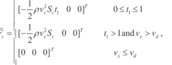
The drag parachute force Fc is related to the forward taxiing speed, so when the speed decreases to a small settled value v , the impact of the drag parachute will become inefficient. In addition, releasing the d drag parachute need some time so the parachute force increases gradually at first. Then the drag parachute force in the body axis system can be estimated as:
2 1 1 2 1 1 [ 0 0] 0 1 2 1 [ 0 0] 1and , 2 [0 0 0] T x c T c x c x d T x d v S t t F v S t v v v v (18)
where
is the atmosphere density at the airport, Sc is the drag parachute coefficient, t1 is thetaxiing time from the moment the aircraft lands on the ground. The moment in the body axis system is:
0 0 ,
Tc c c
M F h (19)
where hc is the distance between the drag parachute mount point and the aircraft horizontal baseline. ,
(17)
where kl is the structure restriction stiffness, and smax is the
maximum compression stroke of the shock absorber.
2.3 Drag Parachute Force
When the landing gear first touches the ground, due to the high taxiing speed, the tire accelerating process and the tire viscous hydroplaning performance [26], the braking system does not start to work until the aircraft velocity decreases to a certain value. Therefore, the drag parachute is used to decelerate the aircraft from the moment the aircraft lands on the ground.
The drag parachute force
8
between the piston rod and the cylinder, N and u N are the normal pressures of the piston rod and the l cylinder. And the structure restriction force F is given by: l
max
max
max0 0 0 , l l l k s s F s s k s s s s (17)
where k is the structure restriction stiffness, and l s is the maximum compression stroke of the max
shock absorber.
2.3 Drag Parachute Force
When the landing gear first touches the ground, due to the high taxiing speed, the tire accelerating process and the tire viscous hydroplaning performance [26], the braking system does not start to work until the aircraft velocity decreases to a certain value. Therefore, the drag parachute is used to decelerate the aircraft from the moment the aircraft lands on the ground.
The drag parachute force Fc
is related to the forward taxiing speed, so when the speed decreases to a small settled value v , the impact of the drag parachute will become inefficient. In addition, releasing the d drag parachute need some time so the parachute force increases gradually at first. Then the drag parachute force in the body axis system can be estimated as:
2 1 1 2 1 1 [ 0 0] 0 1 2 1 [ 0 0] 1and , 2 [0 0 0] T x c T c x c x d T x d v S t t F v S t v v v v (18)
where
is the atmosphere density at the airport, Sc is the drag parachute coefficient, t1 is thetaxiing time from the moment the aircraft lands on the ground. The moment in the body axis system is:
0 0 ,
Tc c c
M F h (19)
where hc is the distance between the drag parachute mount point and the aircraft horizontal baseline.
is related to the forward taxiing speed, so when the speed decreases to a small settled value
vd, the impact of the drag parachute will become inefficient. In addition, releasing the drag parachute need some time so
.
Fig. 2. Flexible dynamic model of the main landing gear Fig. 2. Flexible dynamic model of the main landing gear