서론
임플란트의 식립 위치는 심미와 기능 그리고 장기간의 성공에 중요하다.1,2 임플란트가 잘못된 위치에 식립된 경 우에는 골열개, 골천공, 주변골흡수, 나사파절, 심미성의 결여, 교합의 이상, 기능 시 불편감 등의 문제를 야기할 수 있다.3,4
최상의 심미를 위해서는 임플란트 식립부의 경조직과 연조직 상태를 고려해야 하고 보철물의 위치에 기준으로 임플란트가 식립되어야 한다.5 2002년 컴퓨터 단층영상 에 기반하여 임플란트의 식립 방향과 깊이를 제어할 수 있는 임플란트 가이드가 등장하였다.6 임플란트 가이드 는 임시 혹은 최종 보철물을 안내하는 삼차원 컴퓨터 유 도 수술로 발전하였고,7 최소 침습법의 개념을 도입한 무 피판 수술이 가이드 이용 시에 추천되었다.8 이러한 임플 란트 가이드는 구강에 착용한 상태에서 임플란트의 식립 이 진행되기 때문에 수술을 방해하지 않는 형태와 안정 성을 가져야 한다.9
임플란트 가이드의 제작은 크게 석고모형을 기반으로 하는 방법과 컴퓨터 단층촬영과 같은 영상자료를 이용하 는 방법이 있다. 석고모형을 이용하는 전통적인 방식은 아크릴릭 레진으로 모형을 덮은 뒤 임플란트가 식립될 부위에 구멍을 생성하여 제작하였다.10 또는 모형상에서 인공치를 배열하여 상실된 치아를 회복한 상태에서 아크 릴릭 레진을 적용 후 임플란트 식립 각도를 예상하여 구 멍을 형성하였다.11,12 첫 번째 방법은 임플란트의 식립 위 치정보만을 가지며, 두 번째 방법은 식립 각도에 대한 정 보 가지고 있었다. 하지만 영상정보 없이 석고모형상에 서 임프란트 가이드를 제작하는 방법은 기저골이 고려 되지 않았기 때문에 59.7%에서 골천공이 발생한다고 보 고되었다.8 이러한 문제점을 해결하기 위해서 컴퓨터 단 층촬영과 같은 영상자료를 적용하게 되었다. 영상자료를 기반으로 하여, 디자인 프로그램 상에서 골의 형태와 인 접치아 위치를 분석한 뒤 임플란트의 식립 위치와 방향 을 설정하여 가이드를 디자인한다. 그리고 디자인된 가 이드를 기계공정으로 재료를 적층하여 제작하는 방식이
Case Report
http://dx.doi.org/10.14368/jdras.2015.31.1.67
*Correspondence to: Du-Hyeong Lee
Assistant Professor, Department of Prosthodontics, College of Dentistry, Kyungpook National University, 2175 Dalgubeoldae-ro, Jung-gu, Daegu, 700-412, Republic of Korea
Tel: +82-53-600-7676, Fax: +82-53-427-0778, E-mail: [email protected]
implant placement using a newly developed ct-based guide program and subtractive manufacturing: case reports
Jung-Wan Park, Kyung-Rok Kim, Hye-Won Kang, Kyu-Bok Lee, Du-Hyeong Lee*
Department of Prosthodontics, School of Dentistry, Kyungpook National University, Daegu, Republic of Korea
Computer-guided surgery utilizing computed tomography is advantageous in placing implants precisely and conveniently. The purpose of the cases was to report a newly developed CT-based guide fabrication program and subtractive manufacturing using resin block. The guided surgery with the program and subtractive manufacturing allows not only precise translation of the treatment plan, but also offers additional significant benefits. (J Dent Rehabil Appl Sci 2015;31(1):67-74)
Key words: implant guide; computer-guided surgery; subtractive manufacturing
Copyright© 2015 The Korean Academy of Stomatognathic Function and Occlusion.
It is identical to Creative Commons Non-Commercial License.
cc
ISSN 2233-4084
1.증례 1
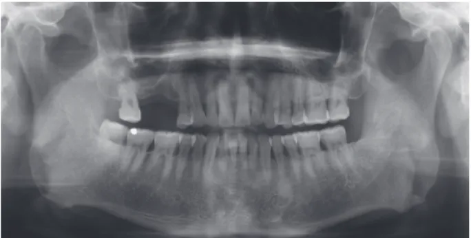
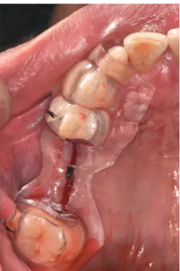
첫 번째 증례는 50세의 남자 환자로 상악 구치부 치아 수복을 주소로 내원하였다(Fig. 1 - 3). #15, 16 부위에 임플란트 지지 고정성 보철물로 치료 계획 후 컴퓨터 단 층촬영을 시행하고 환자의 석고 모형을 데스크탑 스캐 너(Scanner S600; Zirkonzahn, South Tyrol, Italy)로 스 캔하였다. 영상자료와 모형 STL 파일을 임플란트 가이
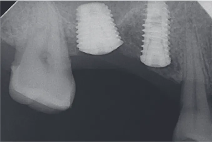
를 식립하였다(Fig. 10). 임플란트는 길이 10.0 mm, 너비 4.7 mm와 길이 7.0 mm, 너비 7.0 mm의 OneQ (Dentis, Daegu, Korea)를 사용하였다. 임플란트 식립 후 치근단 방사선 사진을 촬영하여 계획된 위치와 비교하였다(Fig.
11). 계획된 식립위치와 식립 후 치근단 방사선 사진을 비교한 결과 시상면에서 임플란트 장축간 각도는 2°정 도의 오차를 나타내었다.
Fig. 1. Initial panoramic view.
Fig. 2. Initial clinical photograph; upper view.
Fig. 3. Initial clinical photograph; lateral view.
Fig. 4. Drawing of virtual implant fixture.
Fig. 5. Planning of implant position on sagital plane.
Fig. 6. Planning of implant position on transverse
section.Fig. 7. Designing of implant guide.
Fig. 8. Milling procedure of PMMA block.
Fig. 9. Fabricated implant guide.
Fig. 10. Surgery with implant guide.
2. 증례 2
두 번째는 61세의 여성으로 전반적인 보철 치료를 위 해 내원하였다(Fig. 12, 13). 잔존 치근의 발치 후 하악 우 측 구치부를 임플란트 지지 고정성 보철물로 수복하기
Fig. 11. Periapical view after surgery.
Fig. 12. Initial panoramic view.
Fig. 13. Initial clinical photograph; lower view.
Fig. 14. Drawing of virtual implant fixture.
Fig. 15. Planning of implant position on sagital plane.
Fig. 16. Planning of implant position on transverse section.
Fig. 17. Designing of implant guide.
Fig. 18. Fabricated implant guide.
Fig. 19. Surgery with implant guide.
Fig. 20. Periapical view after surgery.
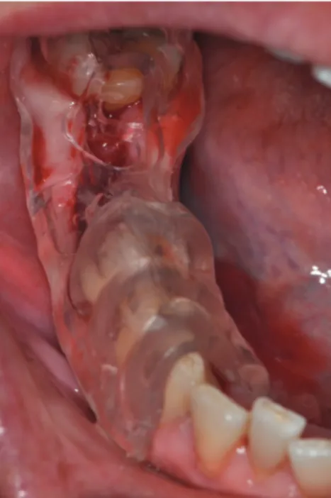
에 국소마취를 시행하고 치조정상에 수평절개를 한 후, 제작된 가이드를 이용하여 임플란트를 식립하였다(Fig.
19). 임플란트는 길이 10.0 mm, 너비 4.2 mm와 길이 7.0 mm, 너비 5.2 mm의 OneQ를 사용하였고, 식립 후 치근 단 방사선 사진을 촬영하여 계획된 위치와 비교하였다 (Fig. 20). 계획된 식립위치와 식립 후 치근단 방사선 사진 을 비교한 결과 시상면에서 3.5°의 오차를 나타내었다.
고찰
본 논문의 증례에서 컴퓨터 단층촬영과 치아 모형 영 상 정보를 이용하여 새로운 임플란트 가이드 제작 프로 그램(DDS-Pro)을 통해 레진 블록을 절삭하는 방식으 로 가이드를 제작하였다. 임플란트 식립을 3차원적으로 계획할 수 있는 프로그램으로는 1993년에 Materialise Dental 사의 SimPlant 프로그램이 처음으로 소개되었
다.16 본 논문에 소개된 DDS-Pro의 경우 Simplant 시 스템과의 비교 시 몇 가지 특징과 장점이 있다. 첫째, DDS-Pro 프로그램에서는 임플란트 고정체의 형태를 세부적으로 조절할 수 있다. DDS-Pro는 고정체의 설계 기능을 부여함으로써 기존의 프로그램이 가지는 제조사 에 대한 의존을 줄였다. Simplant 프로그램의 경우 프로 그램에 탑재된 임플란트 이미지를 술자가 선택하여 적 용하게 되어 있어 술자가 사용하려는 임플란트가 프로 그램에 포함되어 있지 않은 경우에는 가이드 디자인 시 제한이 있다.
설계한 가이드를 술자가 스스로 3D 프린터 혹은 절삭가 공기계를 통해 출력할 수 있는 장점이 있다. 현재 Sim- plant를 포함한 타사의 경우 제조사에서 가이드를 출력 하여 배송해 주는 것이 일반적이다.
임플란트를 식립하기 전과 식립 후 계획된 임플란트 식립 방향과 위치를 비교하기 위해 방사선 사진을 촬영 하였고, 2 - 3°정도의 오차를 확인하였다. 두 증례 모두 식립 전 방사선 사진과 식립 후를 비교했을 때 계획된 부위에 식립되었음을 확인 할 수 있었다. 본 두 증례를 통해 본 프로그램을 이용하여 제작된 가이드가 식립 방 향과 위치를 적절히 유도할 수 있음을 확인 할 수 있었 다.
임플란트 가이드는 적층하는 방식이 아닌 절삭하는 방식으로 제작되었다. 현재 절삭장비를 통해 블록을 절 삭하는 방식은 3D 프린터를 통해 적층하는 방식보다 일 반적으로 제작 속도가 빠르다. 본 증례 가이드의 제작 시간은 약 2시간으로 상대적으로 제작 속도가 빨랐다.
그리고 투명한 아크릴릭 레진 블록을 절삭 가공함으로 써 가이드가 투명하게 제작되었다. 이것은 투명한 재료 를 후처리 없이 절삭함으로써 가능 하였는데, 이러한 투 명성은 임플란트 가이드를 사용함에 있어서 장점이 될 수 있다.
본 증례에서는 치아와 치은의 데이터를 얻기 위해 치 아 석고 모형을 스캔하였다. 인상 채득 과정을 통해 제 작된 치아 석고 모형은 실제 구강의 형태와 다를 수 있 다. 그러므로 인상 채득 과정 없이 구강 내를 구강내 카 메라로 영상 채득 후 프로그램에 바로 전송하여 가이드 제작에 이용된다면 가이드의 정확도 향상에 기여할 것 으로 사료된다.
결론
최근에 개발된 컴퓨터 단층촬영에 기반한 임플란트
location and related success rate. J Oral Implantol 2007;33:211-20.
2. Buser D, Martin W, Belser UC. Optimizing esthet- ics for implant restorations in the anterior maxilla:
anatomic and surgical considerations. Int J Oral Maxillofac Implants 2004;19 Suppl:43-61.
3. Beretta M, Poli PP, Maiorana C. Accuracy of computer-aided template-guided oral implant place- ment: a prospective clinical study. J Periodontal Implant Sci 2014;44:184-93.
4. Tarnow DP, Cho SC, Wallace SS. The effect of in- ter-implant distance on the height of inter-implant bone crest. J Periodontol 2000;71:546-9.
5. Garber DA, Belser UC. Restoration-driven implant placement with restoration-generated site develop- ment. Compend Contin Educ Dent 1995;16:796, 798-802, 804.
6. Orentlicher G, Abboud M. Guided surgery for im- plant therapy. Oral Maxillofac Surg Clin North Am 2011;23:239-56, v-vi.
7. van Steenberghe D, Glauser R, Blombäck U, An- dersson M, Schutyser F, Pettersson A, Wendelhag I. A computed tomographic scan-derived custom- ized surgical template and fixed prosthesis for flap- less surgery and immediate loading of implants in fully edentulous maxillae: a prospective multicenter study. Clin Implant Dent Relat Res 2005;7 Suppl 1:S111-20.
8. Van de Velde T, Glor F, De Bruyn H. A model study on flapless implant placement by clinicians with a different experience level in implant surgery.
Clin Oral Implants Res 2008;19:66-72.
9. Patras M, Martin W, Sykaras N. A novel surgical template design in staged dental implant rehabilita- tions. J Oral Maxillofac Res 2012;3:e5.
10. Kennedy BD, Collins TA Jr, Kline PC. Simplified guide for precise implant placement: a technical note. Int J Oral Maxillofac Implants 1998;13:684-8.
11. D’Souza KM, Aras MA. Types of implant surgi- cal guides in dentistry: a review. J Oral Implantol 2012;38:643-52.
12. Becker CM, Kaiser DA. Surgical guide for dental implant placement. J Prosthet Dent 2000;83:248- 51.
13. Marquardt P, Witkowski S, Strub J. Three-dimen- sional navigation in implant dentistry. Eur J Esthet Dent 2007;2:80-98.
14. Cassetta M, Stefanelli LV, Giansanti M, Calasso S.
Accuracy of implant placement with a stereolitho- graphic surgical template. Int J Oral Maxillofac Im- plants 2012;27:655-63.
15. Pattanaik S, Pattanaik BK. Fabrication of a surgical guide with help of a milling machine by ridge map- ping method. J Indian Prosthodont Soc 2013;13:61- 5.
16. Azari A, Nikzad S. Computer-assisted implantol- ogy: historical background and potential outcomes- a review. Int J Med Robot 2008;4:95-104.
*교신저자: 이두형
(700-705) 대구광역시 중구 달구벌대로 2175 경북대학교 치의학전문대학원 치과보철학교실 Tel: 053-600-7661|Fax: 053-427-0778|E-mail: [email protected]
접수일: 2014년 11월 12일|수정일: 2015년 2월 6일|채택일: 2015년 1월 8일
컴퓨터 단층영상에 기반한 임플란트의 삼차원 컴퓨터 유도 수술은 임플란트 가이드를 이용함으로써 수술시 정확도와 편의성을 향상시킨다. 본 증례에서는 최근에 개발된 임플란트 가이드를 제작 프로그램을 이용하여 가이드를 설계하고 아크릴릭 레진을 절삭하는 방식으로 제작하여 임상에 적용하였다. 본 프로그램을 이용한 가이드의 설계와 제작시 이로 운 점이 있었기에 이를 보고하는 바이다.
(구강회복응용과학지 2015;31(1):67-74)
주요어: 임플란트 가이드; 삼차원 컴퓨터 유도 수술; 절삭 가공