Effect of Air Gap Thickness on Top Heat Loss of a Closed-loop Oscillating Heat Pipe Solar Collector
Kim-Bao Nguyen1⋅Soon Ho Choi2⋅Doo Ho Yoon3⋅Jae Hyuk Choi4⋅Cheol Oh4⋅Seok Hun Yoon†
(Received October 29, 2009 ; Revised November 11, 2009 ; Accepted, November 11, 2009)
Abstract:In this paper, effect of air gap thickness between absorber plate and glass cover on top heat loss of a closed loop oscillating heat pipe (CLOHP) solar collector was investigated. The CLOHP, which is made of copper with outer diameter of 3.2mm and inner diameter of 2.0mm, comprises 8 turns with heating, adiabatic and cooling section.
The heating section of the heat pipe was attached to absorber plate which heated by solar simulator simulated by halogen lamps. The cooling section of the heat pipe was inserted into collector's cooling section that made of transparent acrylic. Temperatures of absorber plate, glass cover, and ambient air measured by K-type thermocouple and were recorded by MV2000-Yokogawa recorder. Top heat loss coefficients and top heat loss of the collector corresponding to some cases of air gap thickness were determined. The result of experiment shows the optimal air gap thickness for minimum top heat loss of this solar collector.
Key words:Closed-loop oscillating heat pipe (CLOHP), Solar simulator, Top heat loss coefficient, Top heat loss, Air gap thickness, Solar collector
†Corresponding Author (Division of Marine System Engineering, Korea Maritime University, E-mail : [email protected], Tel: 051-410-4288)
1 Graduate School of Marine System Engineering, Korea Maritime University 2 R&D Center of DHP Company
3 Busan Campus of Korea Polytechnic. VII
4 Division of Marine System Engineering, Korea Maritime University
Nomenclature
h1c Convective heat transfer coefficient between plate and cover, [W/m2 K]
Nu Nusselt number Ra Rayleigh number Gr Grashof number Pr Prandtl number
g Acceleration of gravity, [m/s2] ΔT Temperature difference between
plate and cover, [K]
Qt Top heat loss rate from front surface, [W]
L Air gap thickness between plate
and cover, [m]
h2c Convective heat loss coefficient from cover to ambient air, [W/m2 K]
V Wind velocity, [m/s]
h1r Radiative heat loss coefficient from plate to cover, [W/m2 K]
Tp Absorber plate temperature, [0C]
Ts Sky temperature, [0C]
Ta Ambient air temperature, [0C]
Tab Absorber plate temperature, [0C]
h1 Total heat transfer coefficient from plate to cover, [W/m2K]
h2 Total heat transfer coefficient
from cover to ambient, [W/m2K]
Ut Total top loss coefficient from plate to ambient, [W/m2K]
K Thermal conductivity of air, [W/mK]
Ac Area of collector, [m2]
I Incident solar intensity, [W/m2] β Collector angle of inclination, [0] α Thermal diffusivity of air, [m2/s]
ν Kinematic viscosity of air, [m2/s]
σ Stefan’s constant
εp Emissivity of absorber plate εg Emissivity of glass cover
εff Effective emissivity of plate-cover system
′
1. Introduction
Thermal performance of oscillating heat pipe and solar collectors were investigated so much in previous researches. S.
Rittidech and S. Wannapakne[1]
investigated performance of a solar collector by closed-end oscillating heat pipe. The results confirmed that the anticipated fluctuation in collector efficiency was depended on the time of day, solar irradiation, ambient air temperature and mean temperature of absorber plate. Piyanun Charoensawan and Paradit Terdtoon[2] investigated the performance of horizontal closed loop oscillating heat pipe (HCLOHP). This study showed that, HCLOHP could not operate at lower than 500C of evaporating section and operating temperature depends on the number of turns of heat pipe. S. Rittidech, P. Terdtoon, M.
Murakami, P. Kamonpet and W.
Jompakdee[3] studied the effect of working fluids (R123, Ethanol), inner diameter and the number of turns of closed-end oscillating heat pipe on the heat flux. R. R. Avezov, V. G. Dyskin and N. R. Avezova[4] researched the water heating flat plate solar collector to get optimal closed air layer for a light- absorbing heat exchanger panel-transparent cover system. M. Mahasudan, G. N.
Tiwari, D. S. Hrishikeshan and H. K.
Sehgal[5] researched the optimization of heat loss in normal and converse flat-plate collector configurations.
Seok-Hun Yoon, Cheol Oh, and Jae-Hyuk Choi[6] investigated the heat transfer characteristics of self oscillating heat pipe. The result showed that the effective thermal conductivity of this kind of heat pipe was 1000-2000 times in comparison with the conventional thermal conductivity of copper. Oscillating heat pipe does not need pumping power, its’
simple structure and large quantities of heat can be transported through a small cross-section area. Thus, the oscillating heat pipe can be used in many industrial fields including solar energy water heating system.
Heat loss in most commercial flat-plate solar collectors occurs due to convective and radiative loss from the absorber surface[7]. To improve collector efficiency, these losses from front and back surfaces must be reduced to minimum. In this paper, top loss coefficient and top heat loss was determined to investigate the effect of the air gap thickness between
absorber plate and glass cover on top heat loss of CLOHP solar collector.
2. Analysis
The thermal loss to the surrounding is an important factor of a flat-plate solar collector. Heat is lost from the plate through the glass cover (top loss), through the back insulation (bottom loss) and through the edges of collector referred as edge loss. These losses take place with forms of convection, conduction and radiation heat transfer. However, back and edge losses can be minimized by choosing proper insulation material and their thickness. The most important heat loss in a flat plate solar collector is top loss. Therefore, the components that effect on it need to be investigated in details.
These steps below show procedures to determine top heat loss of a flat plate solar collector.
2.1 Convective heat transfer coefficient
The convective heat transfer coefficient between absorber plate to the cover inclined an angle to the horizontal can be calculated as[7]
(1)
Nusselt number, Nu, for air between absorber plate and glass cover is calculated by expressions:
cos
(2a)
cos
sin
(2b)
cos
(2c) (2d)
The '+' exponent means that only the positive value of the term in square bracket is to be considered and zero is to be used for negative value, and , the angle of inclination varies between 00-750, the Rayleigh number, Ra, is given by:
Pr
′
(3)
If 75° ≤ β ≤ 90° :
sin
(4a) sin (4b)
m ax (4c)
The Nu number is the maximum value of the three quantities separated by comma and A is the ratio of length of collector plate inclined to spacing between cover and absorber plate.
The convective heat loss coefficient from cover to ambient air is given and V is the wind speed over collector in m/s:
(5)
2.2 Radiative heat transfer coefficient
The radiative heat loss coefficient from plate to cover can be given as
(6)
(7)
(8)
(9)
2.3 Total top loss coefficient
The total heat loss coefficient from plate to cover is sum of h1c and h1r,
(10)
And that from the cover to ambient as:
(11)
The total top loss coefficient from plate to ambient is given by:
(12)And the rate of top heat loss is calculated as:
(13)
The formulas from (1) to (13) show that the rate of top heat loss of the collector depends on air gap thickness, wind velocity, ambient air temperature, temperatures of absorber plate and glass cover. It is impossible to control environment conditions to reduce top heat loss, but it is possible to adjust some construction parameters including air gap thickness between absorber plate and glass cover. That is why we designed, constructed and investigated effect of air gap thickness on top heat loss of this kind of solar collector.
3. Experiments and procedures
Figure 1 shows the detailed dimensions
and configuration of the CLOHP solar collector which consists of heating, adiabatic and cooling section. The CLOHP, which was made of copper, was attached to absorber plate heated by solar simulator. Solar simulator was formed by twelve 300W-halogen lamps. The cooling section of CLOHP was inserted into collector’s cooling box made of transparent acrylic. Before charging working fluid, the air in the CLOHP was withdrawn to vacuum pressure of 10-3Pa by diffusion type vacuum pump. Frame of the collector was made of aluminum at four sides and bottom side. And top cover of the collector was made of transparent glass and sealed with silicone. The bottom and the four sides were insulated by poly-urethane foam. The case of the collector consists of upper and lower parts separately for assembling with an adjustable thickness of air gap easily. Refrigerating water bath was used to supply cooling water for cooling section of the collector.
Temperature of cooling water can be set at water bath. Radiation intensity of solar simulator was adjusted by voltage regulator and recorded by Yokogawa recorder via LP-PYRA-50-Pyranometer.
To measure temperatures of absorber, glass cover and ambient air, K type thermocouples were used. Measuring points of absorber plate and glass cover are marked in Figure 2. All thermocouples were connected to 2000MV-Yokogawa recorder. Cooling water flow rate was adjusted to 0.15l/min, which was recommended by the ASHRAE and the temperature of cooling water was set to
250C at water bath. The solar simulator was fixed and arranged parallel with a controllable inclined angle stand. In this case, it was adjusted to inclination angle of 300. Solar irradiation intensity was adjusted to 200, 400, 500, 600, 700, and 800W/m2. Experiment was performed with air gap thicknesses of 5, 15, 25, and 35mm.
Absorber plate Copper
tube Insulation material
L Glass cover 50 30
Water in
Cooling section
Heating section
For charging fluid To vac. .
pump
24565
P 55
500
Water out
Adiabatic section
Figure 1: Collector’s dimensions and configuration
W ater In
Water out
MV 2000 Yokogaw a recorder
P Water bath
Flow meter
Thermocouple
Pressure transducer P F
F
Figure 2: Diagram of experimental apparatus
4. Results and discussion
The change of temperature of absorber
plate is shown in Figure3. It shows that temperatures of absorber plate depend strongly on the air gap thickness of the collector. At first, temperatures of absorber plate increase with increasing of air gap thickness and after that, they decrease with bigger values of 25mm.
Temperatures of absorber plate corresponding with 800W/m2 of solar intensity are smaller than that of solar intensity of 500W/m2, 600W/m2, and 700W/m2. It means that it is high enough energy to evaporate the working fluid inside the heat pipe in case of 800W/m2 and it makes the working fluid oscillate quickly, and as this result, thermal heat in the heat pipe can be transported to cooling section more effectively.
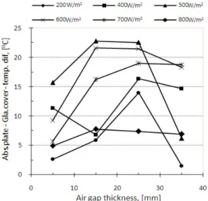
Temperature differences between absorber plate and glass cover are shown in Figure4.
Figure 3: Absorber plate temperatures versus air gap thickness
Figure 4: Absorber plate-glass cover temperature difference versus air gap thickness
Figure 5: Convective heat transfer coefficients, h1c versus air gap thickness
The effect of air gap thickness on convection heat transfer coefficient, h1c, from absorber plate to glass cover is shown in Figure5. The maximum values of convective heat transfer coefficient are reached corresponding with 5mm of air
gap thickness and theirs minimum are reached at 15mm. It means that heat conduction happened very intensively at 5mm of air gap thickness because of small air gap thickness between absorber plate and glass cover, and convective heat transfer coefficient is almost equal to heat conductivity. In cases of air gap thickness of 15mm, the Nusselt number is little bigger than unity, but this thickness is enough to make the high thermal conduction resistance that makes low heat loss coefficient.
Figure 6: Total top loss coefficients, Ut versus air gap thickness
The combination of these results makes top heat loss coefficient, Ut, minimize at air gap thickness of 15mm as shown in Figure 6. The convective heat transfer coefficient corresponding with irradiation intensity of 800W/m2 is small because it is enough energy for heat pipe working effectively and it makes the temperature of heat absorb plate very low.
The trend of the change of the rate of top heat loss in Figure7 is similar to the trend of the change of total heat loss coefficient. The rate of top heat loss, Qt, is minimized at the air gap thickness of 15mm in most ranges of solar irradiation intensity because convective heat transfer coefficient and total heat loss coefficient reach the minimum values at this air gap thickness as shown in above figures.
Figure 7: The rates of top heat loss versus air gap thickness
Figure 8: Ratio of top loss to incident solar energy versus air gap thickness
The effect of air gap thickness on the performance of collector can be judged by the ratio of thermal top heat loss to incident solar energy. The change of this ratio versus the air gap thickness corresponding with wide ranges of solar irradiation intensity is shown in Figure 8.
The higher the solar irradiation intensity is, the smaller the top loss-solar irradiation ratio is. It means that much more thermal heat can be transported from heating to cooling section of the collector because heat pipe works more effectively. At lower solar irradiation intensity, it has not enough driving force for working fluid to circulate strongly.
Therefore, the thermal heat absorbed can be stagnated inside collector’s heating section and it makes much more heat loss of the solar collector.
Figure 8 also shows that the smallest values of the ratio of top heat loss to incident solar energy, which could give the highest efficiency for collector, corresponds with the air gap thickness of 15mm for most ranges of solar radiation intensity.
5. Conclusion
In this research, a CLOHP flat-plate solar collector was constructed and experiment was performed to investigate the effect of air gap thickness between absorber plate and glass cover on top heat loss of the collector. Thermal top heat loss coefficients and the rate of top heat loss of the collector depend on both the air gap thickness and solar radiation intensity.
The best air gap thickness of the collector
is 15mm for most ranges of solar intensity. At this air gap thickness, the collector could give the highest performance because of the smallest value of thermal top heat loss.
References
[1] S. Rittidech et al, “Experiment study of the performance of a solar collector by oscillating heat pipe”, Applied Thermal Engineering 27, pp. 1978-1985, 2007.
[2] Piyanun Charaensawan et al, “Thermal performance of horizontal closed loop oscillating heat pipes”, Applied Thermal Engineering 28, pp. 460-466, 2008.
[3] S. Rittidech et al, “Correlation to predict heat transfer characteristics of a oscillating heat pipe at normal operating condition”, Applied Thermal Engineering 23, pp. 495-510, 2003.
[4] R. R. Avezov et al, “Thermal optimization of closed air layer of a light-absorbing heat exchange panel-transparent cover system of water-heating flat-plate solar collectors”, Applied Solar Energy, vol. 43, No. 4, pp. 207-210, 2007.
[5] M. Mahasudan et al, “Optimization of heat losses in normal and reverse flat-plate collector configurations: Analysis and performance”, Energy Con.& Mgmt vol. 21, pp. 191-198, 1981.
[6] Seok-Hun Yoon et al, “A study on the Heat transfer characteristics of self-oscillating heat pipe”, KSME international Journal, Vol. no. 3, pp.
354-362, 2002.
[7] G.N. Tiwari, “Solar energy fundamental, design, modeling and application”,
Center for Energy Study, Indian Institute of Technology, Delhi, New Delhi-110 016, India, 2002.
Author Profile
Kim-Bao Nguyen
was born in Thaibinh Province, Vietnam in 1983. He received B.E from Vietnam Maritime University, Haiphong, Vietnam in 2006. He has worked for VIMARU from 2006 to 2008. Now, he has been studying at Korea Maritime University (Master degree).
Soon Ho Choi
He received B.S and M.S degrees from Korea Maritime University and Ph. D.
degree from Tokyo university in Japan.
Dr. Choi have worked for DHP Eng.
Co., Ltd. as a chief of R&D Center and CTO. Dr. Choi's research interests are in the area of nanoscale heat transfer, phase change phenomena and a heat exchanger design.
Doo Ho Yoon
He received his B.S. degree from Pukyong National University, M.S. and Ph. D. degrees from Korea Maritime University. He is currently a professor in Busan Campus of Korea Polytechnic. VII.
His research interests are thermal engineering, heat transfer et al.
Cheol Oh
He received his B.S and M.S degrees from Korea Maritime University and received Ph. D. degree from Hokkaido university. He is currently a professor at the division of marine system engineering in Korea Maritime University.
His research interests are refrigeration, air conditioning, ocean energy et al.
Jae Hyuk Choi
He received his B.S and M.S degrees from Korea Maritime University in 1996, 2000 and Ph.D. degree from Hokkaido university in 2005. He is currently a professor in Korea Maritime University.
Dr. Choi's research interests are reduction of pollutant emission (Soot and NOx), high temperature combustion, laser diagnostics, alternative fuel and hydrogen production with high temperature electrolysis steam (HTES)
Seok Hun Yoon
He received his B.S. and Ph.D. degrees from Korea Maritime University. He is currently a professor at the division of marine system engineering in Korea Maritime University. His research interests are thermal engineering, solar energy et al.