An Experimental Study on the Improvement of Turbocharger Lag by Means of Air Injection in a Turbocharged Diesel Engine
Nag-Jung Choi†․Seong-Mo Oh1
(Received September 14, 2010; Revised October 11, 2010; Accepted November 11, 2010)
Abstract:An experimental study was performed to investigate the improvement of response performance of a turbocharged diesel engine under the operating conditions of low speed and fast acceleration. In this study, the experiment for improving the low speed and acceleration performance is performed by means of injecting air into the intake manifold of compressor exit during the period of low speed and application of a fast acceleration from low speed. The effects of air injection into the intake manifold on the response performance were investigated at various applicant parameters such as air injection pressure, accelerating rate, accelerating time, engine speed and load. The experimental results show that air injection into the intake manifold at compressor exit is closely related to the improvement of turbocharger lag under low speed and accelerating conditions of a turbocharged diesel engine. During the rapid acceleration period, the air injection into the intake manifold of turbocharged diesel engine indicates the improvement of the combustion characteristics and gas pressure in the cylinder. At low speed range of the engine, the effect of air injection shows the improvement of the pressure distribution of turbocharger and combustion pressure during the period of gas exchange pressure.
Key words:Turbocharger lag, Turbocharged diesel engine, Fast acceleration, Air injection, Response performance
†Corresponding Author( Division of Mechanical Design Engineering, Chonbuk National Universisty) E-mail : [email protected], Tel : 063)270-4765
1 Division of Mechanical Automotive Engineering, Wonkwang Universisty
Nomenclature
Comp : compressor L : load (N.m)
n : engine speed (rpm)
P : pressure (Pa) or pressure transducer Pair : air injection pressure (Pa)
Pcyl : cylinder pressure (Pa) R : air pressure regulator
T : temperature (K) or thermometer Turb.: turbine
Tin : turbine inlet temperature (K)
Acc. time : the time of rapid acceleration (sec)
Acc. rate : the rate of rapid acceleration (%)
IVO : intake valve open EVO : exhaust valve open
1. Introduction
The power output of a diesel engine is
directly related to the amount of fuel burnt in cylinders. The power produced by an engine depends on the quantity of intake air available.
In a diesel engine, the extra air is supplied to burn more fuel, and this is provided by the external supply of turbocharger.
One of the methods for improving power output performance per unit weight of the engine is to use the turbocharger, which is driven by the exhaust gas obtained from the engine cylinders.
A turbocharged diesel engine has a good characteristics that can improve fuel consumption rate, exhaust emissions, and the increase of specific power output of the engine.
In order to increase the power output and to save the energy, the turbocharged diesel engines are usually used for automotive engines.
But these engines occur turbocharger lag during the transient condition such as a fast acceleration or a sudden large load application, and then result in a worse response performance than those of naturally aspirated engines. By the adopting the turbocharged diesel engine, the maximum thermal efficiency is increased, while turbocharged vehicle has a weak point of poor drivability under transient running conditions when the turbocharger does not work effectively, especially at low speed operation and fast acceleration by the control of fuel-pump rack.
Quick changes in rack position do not result in instantaneous response of the turbocharger, due to its inertia and
compressibility of the exhaust gas with the engine. Thus the air-fuel ratio quickly decreases to a very low value and the mixture occurs incomplete combustion;
although much quantity of fuel can be rapidly injected into the cylinders, the turbocharger is slow to respond and provide a corresponding increase in air for the combustion.
For this reason, a study on the investigation and the improvement of transient response performance is to be a very important subject [1].
Numerous studies for the improvement of the transient response of turbocharged diesel engines are focused on the optimum design and control of turbocharger [2-3].
Also, the improvement of turbocharger performance and the transient characteristics of diesel engine have studied by many researchers [4-6].
Considerable work has been done dealing with the transient characteristics and influencing factors for the diesel engine with a turbocharger such as acceleration performance, starting stability, sudden large load, and the speed range of the engine [7-10].
Most of previous papers have described the simulation studies of the matching of turbocharger and transient performance of a turbocharged diesel engine. However, the experimental works for the improvement of response characteristics are scarcely reported [11-12].
In the turbocharged diesel engine, the thermodynamic intensive parameters such as gas pressure and temperature in the engine, turbocharger conditions (pressure and temperature), pressure fluctuation of
intake and exhaust process of gas exchange period, and many factors have influenced on the total performance of the engine.
During the transient operation, the improvements of these transient performances can be achieved both by controlling the fuel flow and supplying air into the cylinder by some external system.
The purpose of this work is to investigate the thermodynamic intensive properties of engine and turbocharger during the rapid acceleration of the low speed range in the turbocharged diesel engine.
Also, the improvement of transient response of turbocharged diesel engine has investigated by means of air injection into the intake manifold at the compressor exit. The effect of air injection into the intake manifold on the factors of response performances such as turbine inlet pressure, compressor exit pressure, combustion pressure and the engine speed are discussed.
2. Experimental
2.1 Experimental apparatus
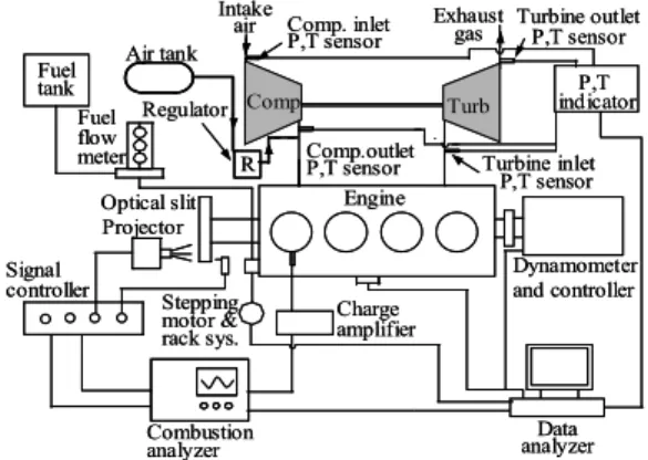
Figure 1 shows a schematic diagram of the test apparatus and measuring system for experiment.
The test rig is equipped with a 150kW eddy current dynamometer, controlled by the electronic system. An automotive 2.476L turbocharged diesel engine was installed in the test apparatus.
The turbocharger of the test engine consists of a radial turbine and centrifugal compressor. The details of the engine and turbocharger are listed in
Table 1. As shown in Figure 1, the experimental apparatus is composed of the test engine, an eddy current dynamometer, control system of fuel and air injection, and data acquisition system.
In this arrangement of test apparatus, the bold solid line is air-supplying line from the air tank to the intake port, and the thin line is the measuring line of transient performance of the engine.
Dynamometer and controller Engine
Comp. inlet P,T sensor Air tank
Fueltank
Optical slit Projector Signal
controller Stepping motor &
rack sys.
Charge amplifier
Combustion
analyzer Data
analyzer indicatorP,T Exhaust
gas Intake
air
Comp.outlet
P,T sensor Turbine inlet P,T sensor R
Turbine outlet P,T sensor
Fuel flow meter
Regulator Comp Turb
Figure 1: Schematic diagram of experimental apparatus
Table 1: Specifications of experimental engine and turbocharger
Engine and turbocharger Specification Engine type
Number of cylinder Combustion chamber Bore × stroke (mm) Piston displacement (cc) Compression ratio Connecting rod length (mm) Maximum power (PS/rpm) Diameter of turbine blade (mm)
4-stroke diesel engine 4
Indirect injection 91.1 × 95.0 2476 21.1 158.4 85 /4200 39mm
Valve timing
Intake open (deg.) Close (deg.) Exhaust open (deg.) Close (deg.)
BTDC 20°
ABDC 48°
BBDC 54°
ATDC 22°
Turbocharger Turbine Compressor
Radial type Centrifugal type
Figure 2 shows the control system of injection pump rack. Fuel control rack is connected to the pulley fitted to rotating
shaft of stepping motor and an reduction gear with gear ratio of 10:1 is used to increase the control of torque.
A rapid acceleration is conducted with the rotation of stepping motor that rotates 0.9 degree per pulse, and its pulse is controlled by means of microcomputer.
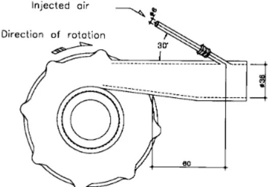
The system of air injection into the intake manifold is composed of the air receiver, regulator valve, timer switch and pipe of air supply. Figure 3 shows the place of air injection system.
The nozzle for injecting air into the intake manifold is embedded in the hole of 7.6mm diameter and 3mm deep, which is drilled at gradient of 30 degree on the surface of compressor delivery pipe.
Compressed air is injected into the intake manifold through the air nozzle with diameter of 6mm.
The arrangements of the engine and turbocharger with air injection system are shown in Figure 4.
Injection time and injection pressure of air are controlled by use of pressure regulator. Pressure sensors are installed to the compressor inlet and exit, turbine inlet and exit, and No.1 cylinder as shown in Figure 4.
Fuel pump rack
Pully Reduction gear(10:1)
Stepping motor
Computer
φ30
Figure 2: Acceleration system of fuel-pump rack
Figure 3: Position of air injection system
Intake air Pressure
transducer
Diesel engine
P,T sensor P,T sensor
Turbine CompressorP,T sensor Air injection Exhaust
gas Exhaust manifold
Intake air Pressure
transducer
Diesel engine
P,T sensor P,T sensor
Turbine CompressorP,T sensor Air injection Exhaust
gas Exhaust manifold
Figure 4: Arrangement of air injection system
2.2 Experimental procedures
Experiments were carried out in the case of with and without the air injection during the operating conditions of low speed and a rapid accelation from low speed, and their results are compared with the response characteristics of a turbocharged diesel engine.
The major parameters measured under the accelerating conditions are engine speed, fuel rack position, turbine inlet pressure and compressor exit pressure, and cylinder pressure.
The experiments were performed for two cases of steady state and transient state conditions at given load and engine speed.
In order to improve the performance of rapid acceleration with the load, the
pressure of the injected air and the load are 100-300kPa and the engine load of 165N.m, respectively.
The flow rate of intake air was monitored by an orifice flow meter and controlled with a precision flow control valve.
Also, the performances of steady state and accelerating operation of the test engine is compared the experimental results of air injection with that of without air injection.
Based on the investigation results, the improvement of transient characteristics is compared with the variations of load and acceleration rate under the air injection. The outputs of sensor elements used for measurement of these parameters are connected with each channel of digital memory, and their data are transferred to a microcomputer.
In order to compare the results of steady test and transient investigation, the test are carried out at 1000 rpm of engine speed under the full load condition. Also, accelerating test was performed at the same speed with the engine load of 165N.m.
3. Experimental and discussion
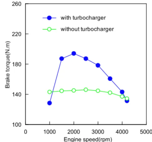
3.1 Effect of air injection at steady state of low speed Figure 5 shows the brake torque on the changes of engine speed in the cases of with turbocharger and without turbocharger at the same diesel engine.
As shown in Figure 5, a turbocharged diesel engine has a good performance at range of engine speeds in whole. But at 1000rpm of low speed, a turbocharged diesel engine has a weak point of poor
torque performance than that of natural aspirated diesel engine in cause of low exhaust gas pressure from engine cylinders, turbocharger inertia moment, resistance of intake air, and so on.
For these reasons, this study was performed to investigate effect of air injection at 1000rpm of low speed.
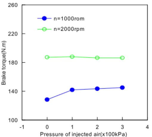
Figure 6 and Figure 7 show effects of air injection on the brake specific fuel consumption and brake torque of the engine at engine speed 1000rpm and 2000rpm with full load.
100
140 180 220 260
0 1000 2000 3000 4000 5000
Engine speed(rpm) with turbocharger without turbocharger
Figure 5: Comparisons of brake torque of the engine with and without turbocharger.
As shown in this diagrams, in the case of air injection with 100kPa, 200kPa and 300kPa of injection pressure at 1000rpm of engine speed, both of brake specific fuel consumption and brake torque are improved in proportion to increase of injection pressure.
But, in the case of 2000rpm of engine speed, effect of air injection is scarely.
From these results, it is observed that turbocharger supplies enough charging air at 2000rpm of engine speed.
100 140 180 220 260
-1 0 1 2 3 4
Pressure of injected air(x100kPa) n=1000rom
n=2000rpm
Figure 6: Effect of injected air on the brake torque of the engine
Figure 8 shows the pressure history of turbine inlet, compressor exit and gas pressure of No.1 cylinder at three kinds of air injection pressure at engine speed of 1000rpm. As shown in Figure 8, in the case of low speed, both the turbine inlet and compressor exit pressure increase with an increase of air injection pressure.
This indicates that higher injection pressure of air increases the gas pressure in cylinder and turbocharger performance parameters such as turbine inlet pressure and compressor exit pressure.
230 255 280 305 330
-1 0 1 2 3 4
Pressure of injected air(x100kPa) n=1000rpm
n=2000rpm
Figure 7: Effect of injected air on the brake specific fuel consumption.
Especially, during the period of valve overlap, the effect of air injection into the intake manifold shows the improvement of pressure variation of turbocharger and combustion pressure.
0.8 1.2 1.6 2.0
0 120 240 360 480 600 720
Crank angle(deg.) Cylinder(No.1) Turbine inlet
Comp. exit
n=1000rpm, Pair=no injection
EVO(No.1 cyl) IVO(No.1 cyl)
0.8 1.2 1.6 2.0
0 120 240 360 480 600 720
Crank angle(deg.) n=1000rpm, P
air=200kPa
EVO(No.1 cyl) IVO(No.1 cyl)
0.8 1.2 1.6 2.0
0 120 240 360 480 600 720
Crank angle(deg.) n=1000rpm, Pair=300kPa
EVO(No.1 cyl) IVO(No.1 cyl)
Figure 8: Effect of air injection on the gas exchange process under full load at 1000rpm.
3.2 Effect of air injection under a rapid acceleration 3.2.1 Effect of air injection on the recovery time
In order to investigate the response performance under accelerating operation of a turbocharged diesel engine, the experiment is carried out at various engine conditions with the changes of transient performance factors such as the
rate of a rapid acceleration, accelerating time, injection pressure and engine load.
A rapid acceleration is applied to the fuel pump rack of the engine from 0-10%
to 0-40% in steps of 10%, and accelerating time of 1, 2 and 3 seconds is applied to the engine.
Injection pressure are 100kPa, 200kPa and 300kPa of gauge pressure.
The total length of fuel pump rack, which can be moved, is 36mm at 1000rpm of no load and 26mm at 1000rpm of 165N.m load.
In each engine speed, three kinds of acceleration time (1, 2 and 3 seconds) are applied to the test engine.
Figure 9 shows the effect of accelerating rate on the recovery time to steady state of cylinder pressure, engine speed and turbine inlet temperature.
The recovery time to steady state of cylinder pressure, engine speed and turbine inlet temperature were increased with the increase of rapid accelerating rate.
Pcyl
0 10 20 30 40 50
0.0 1.0 2.0 3.0 4.0 5.0 6.0
Recovery time to final steady state(sec) Pcyl
n Tin
n=1000rpm
Figure 9: Relations between a accelerating rate and recovery time.
As shown in figure, the transient response of the turbocharging factors that affect to the transient performance of test engine are lately recovered in accordance with the increase of the accelerating rate to the steady state of the test engine.
It is also obvious that as the acceleration is applied, the cylinder pressure as an intensive property in an engine responds at first, and in sequent engine speed, and turbine inlet temperature are responded in turn.
Figure 10 shows the effects of air injection on the recovery time of engine speed.
0 10 20 30 40 50
0.0 1.5 3.0 4.5 6.0
Recovery time og engine speed(sec) n=1000rpm Pair=300kPa
Pair=no injection
Figure 10: Effect of air injection on the recovery time of engine speed.
When compared with the response performance due to the air injection, it is clear that the case of air injection with 300kPa of pressure is quite improved.
The difference of recovery time between the case of air injection pressure of 300kPa and without injection of air is gradually increased with the increase of rapid accelerating rate.
3.2.2 Effect of air injection on the cylinder pressure When the fast change of fuel-pump rack from 0 to 20% for 1 second is applied to the engine at 1000rpm with the load of 165N.m, the comparison of cylinder pressure-crank angle diagrams due to the progress of engine cycles with air injection and without air injection are shown in Figure 11.
In the cylinder pressure-crank angle diagrams, the solid line is the case of air injection with 300kPa of injection pressure and the dotted line is the case of no injection of air.
As shown in these diagrams, the cylinder pressures increase in accordance with the increase of the thermodynamic engine cycles.
During the beginning period of transient, the low cycle occurs the low cylinder pressure because the turbocharger is commencing the operating.
At the same cycles the gas pressures in the engine with air injection is greater than that of no injection of the air.
It is clear that air injection into the intake manifold during the rapid acceleration period improve greatly the combustion performances of a turbocharged diesel engine.
3.2.3 Relations of accelerating time and response performance
Figure 12 and Figure 13 show the influences of accelerating time on the thermodynamic transient response of turbine inlet and compressor exit pressures.
0 20 40 60 80
-360 -240 -120 0 120 240 360
Crank angle(deg.) n=1000rpm
L=165N.m acc. rate=20%
Cycle No. =10 Pair=300kPa Pair=no injection
(a)
0 20 40 60 80
-360 -240 -120 0 120 240 360
Crank angle(deg.) Cycle No. =20
(b)
0 20 40 60 80
-360 -240 -120 0 120 240 360
Crank angle(deg.) Cycle No. =35
(c)
0 20 40 60 80
-360 -240 -120 0 120 240 360
Crank angle(deg.) Cycle No. =55
(d)
Figure 11: Effects of air injection on the cylinder pressure due to the progress of engine cycles
1.0 2.0 3.0 4.0
0.0 2.0 4.0 6.0 8.0 10.0
Time(sec)
Acc. time n=1000rpm
L=no load 2sec
1sec Acc. rate=40%
(a)
1.00 1.25 1.50 1.75 2.00
0.0 2.0 4.0 6.0 8.0 10.0
Time(sec) Acc. time
2sec 1sec
n=1000rpm L=no load Acc. rate=40%
(b)
Figure 12: Response performance of turbine inlet and compressor exit pressure on the accelerating without load.
1.00 1.25 1.50 1.75 2.00 2.25
0.0 2.0 4.0 6.0 8.0 10.0
Time(sec)
Acc. time=2sec
Acc. time=1sec turb. inlet
comp. exit n=1000rpm
Acc. rate=20%
L=165N.m
Figure 13: Response performance of turbine inlet and compressor exit pressure on the accelerating time with load.
As illustrated in figures, turbine inlet and compressor exit pressures are largely increased in accordance with the application of slow accelerating time and reached more quickly to the range of their final steady state pressure.
An increase of accelerating time shows the increase of the turbine inlet pressure and the shortening of transient duration.
It is clear from these results that the rapid accelerating time is the main cause of turbocharger lag, which is closely related to the transient response performances of a turbocharged diesel engine.
The effect of rapid acceleration on the transient performance of turbocharger characteristics shows the slow increasing of turbocharger pressure because of turbocharger lag.
3.2.4 Effect of air injection on the accelerating
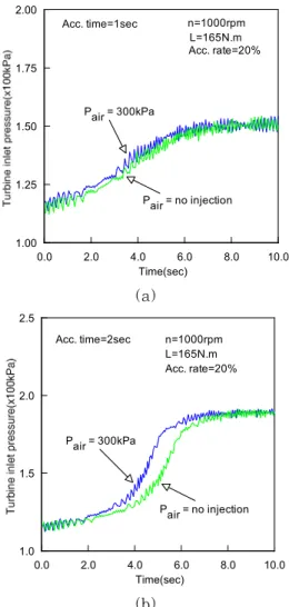
Figure 14 shows the comparison of turbine inlet pressure with the acceleration rate of 20% for 1 second and 2 seconds at the experimental conditions of 1000rpm and 165N.m of engine load.
In the case of supplying air with the 300kPa of injection pressure, it is obvious that air effects on the turbine inlet pressure appear a greater recovery response when acceleration is applied to the engine for 2 seconds than that for 1second.
As can be seen in Figure 14, the longer accelerated time results in the improvement for the response performance and fast recovery of turbine inlet condition.
1.00 1.25 1.50 1.75 2.00
0.0 2.0 4.0 6.0 8.0 10.0
Time(sec)
n=1000rpm L=165N.m Acc. rate=20%
Acc. time=1sec
Pair = 300kPa
Pair = no injection
(a)
1.0 1.5 2.0 2.5
0.0 2.0 4.0 6.0 8.0 10.0
Time(sec) n=1000rpm L=165N.m Acc. rate=20%
Acc. time=2sec
Pair = 300kPa
Pair = no injection
(b)
Figure 14: Effect of injection pressure on the response performance of turbine inlet pressure with load.
4. Conclusion
An experimental study under the low speed and a rapid acceleration operation has performed to investigate the effect of air injection into the intake manifold at compressor exit on the response performance of the turbocharged diesel engine.
Based on the results obtained throughout this study, the following conclusions are summarized.
1. At low engine speed range of steady
state, the effect of air injection into the intake manifold shows the improvement of engine performance and pressure variation of turbocharger and combustion pressure during the period of gas exchange process.
2. When the rapid acceleration was applied to the test engine, first of all cylinder pressure responded, and sequently engine speed, pressure of turbine inlet and compressor exit were responded in turn
3. When the engine is rapidly accelerated in the load condition, the recovery time of turbine inlet pressure is a very longer than that of the condition without the load.
An increase in the accelerating time shows the increase of the turbine inlet pressure and the shortening of transient duration.
4. As the rate of a rapid acceleration for the engine further increased, the transient performance factors of the test engine begin the response lately and require a long time to reach to their final steady state conditions.
5. Effect of air injection on the gas pressure in the engine indicated that cylinder pressure increased in accordance with the increase of air injection pressure.
Also, accelerating time of fuel-pump rack is the main cause of the turbocharger lag, which has largely influence on the transient response of the engine.
References
[1] H. Gimmel, H. P. Holzt and H.-J.Weimann, “Computerized simulation of the acceleration characteristics of an exhaust gas turbocharged
automotive diesel engine,” Proceedings of Turbocharging and Turbochargers, I. Mech. E., London, England, paper C34/82, pp. 37-48, 1982.
[2] Y. Shimamoto, K. Kanamaru and J. S.
Choi., “Prediction of performance of turbocharged four cycle diesel engine,”
Transaction of JSME, vol. 52, pp.
3107-3113, 1986.
[3] W. A. Spaker, “The aerodynamic design of variable power turbine for turbochargers,” SAE paper no. 920041, pp. 62-66, 1992.
[4] F. Nishiguchi, Y. Sumi and K.
Yamane, “Reduction in the polar moment of inertia of an automotive turbocharger by controlling aerodynamic blade loading,” Proceedings of Turbocharging and Turbochargers, I.
Mech. E., London, England, paper C34/82, pp. 123-127, 1982,
[5] K. N. Pattas and A. M. Stamatelos,
“Transient behaviour of turbocharged engine vehicles equipped with diesel particulate traps,” SAE paper no.
920361, pp. 532-539, 1992.
[6] C. S. Lee and N. J. Choi, “A study on the characteristics of transient response in a turbocharged diesel engine,” Proceedings of IPC6, KSAE, Seoul, Korea, pp. 73-80, 1991.
[7] J. D. Ledger, R. S Benson and H.
Furukawa, “Improvement in transient performance of a turbocharged diesel engine by air injection into the compressor,” SAE paper no. 730665, pp. 2412-2423, 1973.
[8] Y. Matsura, N. Nakaza, Y. Kobayashi, H. Ogita and T.Kawatani, “Effects of various methods for improving vehicle
startabilty and transient response of turbocharged diesel trucks,” SAE Paper no. 920044, pp. 11-26,1992.
[9] S.Maulice, K. Lee, S.Watanabe, H.
Nagakura, M.Shiratsuchi, H. Sugihara and M. Ienaga, “Improvement of a turbocharged and intercooled diesel engine powered vehicles startability by means of a three wheel turbocharger (TWT),” SAE paper no.
945018, pp. 163-170, 1994.
[10] M. Ohtani, K. Akiba and H. Yoshiki,
“The improvement of vee eight engine performance in low speed range,”
Proceedings of Turbocharging and Turbochargers, I. Mech. E., London, England, paper C34/82, pp. 7-18, 1982.
[11] N. J. Choi and C. S. Lee, “A study on the response characteristics of a turbocharged diesel engine on the operation conditions of a rapid acceleratio,” Journal of the Korean Society of Marine Engineering, vol.19, no. 3, pp. 33-41, 1995.
[12] C. J. Poplawsky, L. Lindbreg, S. Robb and J.Roundy, “Development of an advanced ceramic turbine wheel for an air turbine starter,” SAE paper no.
921945, pp. 1649-1659, 1992.
Author Profile
Seong-Mo Oh
He received the B.E. and M.E. degree in Mechanical Engineering from Wonkwang University in 1992 and 1994 respectively. He received Ph.D. degree in Mechanical Automotive Engineering from Wonkwang University in 1999. He is currently a researcher in Wonkwang University in chonbuk. His research interests include lubricational and tribological characteristics of engine.
Nag-Jung Choi
He received the B.E. and M.E. degree in Mechanical Engineering from Dong-A University in 1981 and 1983respectively.
He received Ph.D. degree in Mechanical Engineering from Hanyang University in 1995. He is currently a professor in Division of Mechanical Design Engineering at Chonbuk National University in Jeonju. His research interests include performances of internal combustion engine