Ⅰ. 서 론
1. 악구강 수복치료를 위한 치과 임플랜트 술식 의 필요성
완전 무치악 환자나 부분 무치악 환자의 보철학 수 복은 골유착성 임플랜트가 개발되기 전에는 국소의 치나 총의치에 의한 통상적인 보철치료가 시행되었 다. 그러나 이러한 가철성 보철은 의치의지지, 유지 및 안정이 충분하지 못하여 환자의 저작기능 회복에 많은 문제점을 보여 왔다. 또한 구강 점막의 많은 부 위를 피개하여 이러한 보철물은 많은 환자가 거부하 였다. 이의 해결방법으로 골유착성 임플랜트가 개발 되어 저작 및 심미기능의 회복에 탁월한 효과를 환자 에게 제공할 수 있다.(1, 2, 11)완전 무치악환자가 총의 치장착시 70N의 최대 교합력을 보여주나 임플랜트 수복환자는 평균 280N(157-643N)의 교합력을 보여 주어 자연치와 비슷한 교합압을 나타낸다.(12, 13)또한 저작효율도 총의치보다는 월등히 향상되어 환자가 임플랜트 보철을 선호한다. 이러한 임플랜트 보철의 궁극적 성공은 골유착 부위가 장기간 파괴되지 않고 안정된 상태로 잔존하여야 된다.(3, 21, 22, 23) 골유착성 임플랜트 실패의 두 가지 형태는 감염과 과하중
(overload)이며, titanium과 연조직, 골조직과의 우 수한 생체적합성을 보이므로 감염에 의한 실패는 빈 도가 적다.
골유착성 임플랜트와 주위골은 반복되는 저작력에 견디는 하나의 기능적 단위이다.(24, 25)골유착성 임플 랜트에 계속되는 저작력을 가한 후 방사선 소견에서 관찰되는 것과 같이 임플랜트 주위의 치조골은 계속 되는 기능적 적응을 한다. 이러한 개념을 Wolf’s law라고 하며 bone remodeling의 경과와 평형은 기계적 기능에 의해 영향을 받는다. Radiopacity가 증가하고 bone trabecule이 재배치되는 것을 나타 낸다. 이리하여 trabecular bone을 따라 계면의 미 세운동 없이 가해진 하중이 분산되는 평형이 이루어 진다. 여러 요소들이 이러한 평형을 이해하는데 매우 중요하다. 힘의 크기, 하중주기의 수, 골의 회복능력, 임플랜트의 형태 등이다.(26, 27, 28)이러한 요소 중 다 른 요소는 술자에 의한 조절이 불가능하나 임플랜트 의 형태는 변형되어 주어진 하중조건하에서 응력분 포를 양호하게 유도하여 골의 microfracture를 최 소하하고 remodeling을 촉진하여 형성된 골유착을 장기간 유지할 수 있다.(32, 33)
- 대한 치과 보철학회지 Vol. 35 No. 3, 1997 -
골유착성 임플랜트 고정체의 설계변화에 따른 응력분포에 관한 삼차원 유한요소 분석적 연구
*서울대 치과대학 보철학교실
**연세대 치과대학 보철학교실
***서울대 치대 치주학교실
허성주*ㆍ한종현**ㆍ정종평***
2. 골유착 치과임플랜트의 생역학
임플랜트는 특수한 환경인 구강내에 식립되어 치 아의 역할을 대신하여 정하중 및 동하중을 계속 복합 적으로 받게 되므로 생역학과 연관하여 많은 문제점 들이 발생될 수 있다. Skalak은 골유착성 임플랜트 는 악골과 직접 결합되어 있으므로, 기능시 초래되는 외력은 매식체를 통해 직접 악골에 전달되게 되며, 이러한 외력은 자연치아의 치주인대와 같은 구조에 의한 완압기전에 없어 기하학적인 임플랜트 배열 및 설계가 중요하게 고려된다고 강조하였다.(4) 수평력과 수직력을 갖는 저락력은 주로 수직력에 의해 유도되 지만 하악의 수평운동과 치아교두의 경사에 의해 수 평력이 발생하므로, 수직력 또는 수평력 하에서 고정 체의 수와 배열에 따라 어느 정도의 교합력이 고정체 에 분산되는지 아는 것이 중요하다.(8)
이러한 발생된 응력을 분석하는 방법으로는 전기 저항 스트레인 게이지법, 브리틀 코팅법, 므와레 무 늬 분석법, 광탄성법, 유한요소법 등이 있다.
3. 치과임플랜트의 유한 요소법적 응력분포 연구
주어진 하중에서 치아나 악골 및 임플랜트 고정체 에 발생하는 응력을 연구하는 여러 방법은 각각의 특 정 및 장단점을 가지고 있다. 이러한 방법중 유한요 소법은 종래의 실험적 응력 측정법으로는 해결할 수 없는 불규칙하고 복잡한 기하학적 형태와 다양한 물 성치로 이루어진 구조물에 대해 각각의 특성을 모두 응력분석과정에 포함시킬 수 있으며, 결과로 발생되 는 응력의 크기 및 방향 그리고 변위를 공학적 수치 해석법으로 분석할 수 있다는 장점이 있다. 유한요소 법이란 공학 문제를 수치적으로 푸는 매우 조직적인 방법의 하나이다.(5, 6, 7)유한요소법을 타 근사방법과 비교하는 관점에서 그 특징을 한마디로 요약한다면, 유한요소법은 유한 요소(Finite element)라 불리는 물리적으로 혹은 편 의상 나누어진 요소 위에 정의된 특정성질의 기저함 수(Basis function)를 주어진 문제에 맞는 어떤 적분 형의 원리에 사용하여, 연속체 문제를 유한차원 문제 로 수식화 하는 군사적 방법이다.(16, 18, 20)이 정의에서 위의 두 가지 특징이 타 근사방법과 구별되게 하는
요점이 된다. 예를 들어 소위 Ritz의 방법에서는 근 사함수 즉, 기저함수를 잡는데서 유한요소법에서 요 구되는 특정 성직과 다르고, 유한차분법은(Finite difference method)은 적분 원리와는 상관없이 미 분을 차분(Difference)으로 바꾸어 수식화 하는 것이 다. 유한요소법은 일반적으로 역학과 수리물리학 등 에서 경계치 문제 및 초기치 문제 등의 미분방정식의 해를 구하는 근사해법인데, 이 방법에서는 다루는 영 역 전체를 편리한 데로 유한개의 요소로 분할하고 요 소 내에서 절점(node 또는 Nodal point)이라 불리는 점들을 택한다. 미분방정식에서 미지의 변수는 적절 히 선정한 근사함수의 절점에서 정의된 변수의 값 및 미지변수의 도함수 값들의 선형조합으로 표현된다.
즉, 미지변수 값을 절점 값으로 표현한다. 변분법 또 는 가중잔여법을 이용하면 분할된 개개의 요소내에 서 성립되는 주어진 미분방정식에 등가인 유한요소 방정식이 구해진다. 각 요소의 유한요소방정식을 적 절히 조합하고 주어진 경계조건 및 초기조건을 대입 하여 변형하면 미분방정식과 경계조건 및 초기조건 에 등가인 전체 영역에 대한 유한요소방정식이 구해 진다. 이는 통상다원 연립방정식의 형태를 가지면, 이 연립방정식을 풀어서 그 해를 구하면 미지변수의 절점 값이 결정된다. 즉 미분방정식의 해를 정점에서 의 값으로 구한다.(9, 14, 15)
본 연구의 목적은 치과임플랜트의 가장 기본구조 인 고정체의 설계변화에 따라 하중이 가해졌을 때 악 골 및 고정체의 응력분포를 연구하여 추후 임플랜트 고정체의 설계시 저작하중에 가장 양호하게 반응하 여 골유착을 성공적으로 유지하는 형태를 결정하는 것이다.
Ⅱ. 연구 재료 및 방법
1. 임플랜트 고정체의 형태설계
I-DEAS(SDRC Co.) software를 이용하여 3차원 유한요소 모델을 제작하였다. 이러한 software가 SGI Indigo Ⅱ(250MHz, 64Mbyte main memory) workstation 컴퓨터에 입력되어 계산되었다. 임플
랜트 고정체와 악골의 3차원적 응력분포를 관찰하기 위해 각각의 구조가 따로 설계되었다.
모형은 현재 가장 많이 응용되는 기본 고정체를 (control, Model 1) vernier caliper와 사진의 digitation 및 설계도를 참조하여 제작하였다.
control Model상의 형태와 실제 고정체와 가능한 일 치되도록 설계하였다. 그러나 thread portion은 장 축을 경계로 좌우 대칭으로 설계하였다. 실제로 thread에는 대칭의 형태가 존재하지 않지만 응력분 포는 이러한 가정에 크게 영향받지 않는다고 보고되 었다. 악골은 10㎜정도의 높이와 20㎜의 폭경으로 설계되었다. 그리고 고정체 상부 2㎜와 하부 2㎜는 피질골에 위치되어 bicortical fixation을 부여하였 다. 골과 고정체는 계면을 따라 고정된 결합으로 가
정하였고 고정체는 악골의 중앙에 위치시켰다.(그림 1)
다른 6개의 모형은 Model 1에서 기본 구조를 변경 시켜 설계하였으며(Table 1) 변형된 기본구조에 의해 변화된 응력분포를 연구하였다.
2. 물성 및 설셰구조에 따른 유한요소법적 응력 분포 측정
골의 정확한 물성치가 아직 규명되지 않았으므로 다음과 같은 가정을 하였다. 피질골과 해면골은 isotrophic, homogeneous, Linearly elastic 하며 이러한 가정은 model의 다른 부분에도 적용되었다.
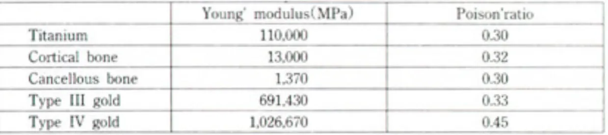
고정체와 지대원주, 지대원주나사는 titanium으로 구성되었으며(19, 39, 40, 41, 42, 43, 44)(Table 3) 다음과 같
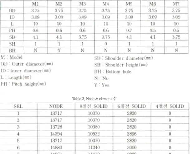
Table 1. Seven different implant design
Table 2. Node & element 수
은 물성치를 대입하여계산하였다.
구조의 이동을 방지하기 위아여 하악골의 하연을 고정 점으로 설정하였다.
Model에 가해지는 하중은 정하중을 사용하였다.
각 모형에 20㎏의 수직하중, 임플랜트에 20㎏의 수평하중, 그리고 20㎏의 30도 경사하중을 가하였 다. 이 연구의 응력분포를 측정하기 위하여 ABAQUS (HKS Co.)를 사용하였다.(29, 30) 각 모형에서 Von Miss Stress를 계산하여 각각 비교하였다. 색상의 차이로써 응력분포가 도식되어 응렵집중이 발생되는 부위를 표시하였다. 이 연구를 위한 post-processing program은 ABAQUS(HKS Co.)를 사용하였다.
Ⅲ. 연구 성적
1. Model 1(그림 2-수직하중),(그림 3-수평하 중),(그림4-30도 하중)
수직하중의 경우에는 임플랜트의 지름이 변화되기 전까지의 나사들은 거의 고르게 힘을 받고 있으며 응 력의 최대치는 나사가 줄어드는 부분에서 발생하고 있다. 그 이유는 이 부분의 경우 부분적으로 깎인 나 사면에 압축력과 전단력이 함께 가해지기 때문이며, 제일 아랫부분의 경우 압축력에 의해서 응력이 높게 나타나고 있다. 임플랜트 내부의 경우에는 지대나사 부위에 응력이 크게 발생하고 있다. 그 이유는 지대 나사가 있는 부위는 고르게 힘이 전단력 형태로 가해 지고 있어 응력이 작지만, 끝나는 부위에서는 힘이 위에서 가해지는 형태가 되기 때문이다.
수직하중과 수평하중은 서로 다른 양상의 응력분 포를 보이고 있다. 수평하중의 경우 임플랜트상단 머 리부분에 응력이 집중되고 있고 임플랜트방향을 따 라 조금씩 감소하고 있다. 이는 수평하중의 경우 골 에 골하단의 고정부를 중심으로 한 moment 하중으 로 가해지는 하중은 고정부를 꼭지점으로 삼각형 형 태를 보이기 때문이다. 그러나 임플랜트의 상단부의 shoulder 때문에 응력이 높게 나타나고 있는 경우는 단면이 줄어서 나타나는 응력집중현상이다.
30도 하중의 경우는 앞에서 언급한 두 하중이 복 합되어 가해지는 경우이다. 그러나 응력의 분포를 보 면 수평하중의 경우와 거의 비슷한 양상을 보이고 있 다. 전체적으로 보면 수평하중의 경우에는 머리부분 에서 가장 큰 응력이 발생하고 있고 그 원인은 임플 랜트의 shoulder가 튀어나와 있기 때문이다. 수직하 중의 경우 응력이 아랫부분의 깎여진 지대나사부위 와 임플랜트 머리부분에서 가장 큰 응력이 발생하도 있으나 분포는 고르게 나타나고 있다.
2. Model 2
Model 2는 Model 1의 하단에 hole을 뚫은 모델이 다. 해석결과를 보면 수평하중의 경우 거의 차이가 없다. 그 이유는 수평하중의 경우 머리부분에 최대 응력이 걸리고 hole의 응력분포에 거의 영향을 미치 지 않는 경우이다. 수직하중의 경우에는 응력분포가 나사가 줄어드는 부위와 hole의 제일 윗부분으로 더 몰리고 있다. 이에 따라서 최대 응력 값도 15%정도 증가하고 있다. 이는 hole이 오히려 나쁜 영향을 준 다는 것을 보여주고 있다.(그림 5)
Table 3. Material properties
3. Model 3
Model 3은 임플랜트의 머리부분의 직경을 나사의 직경과 동일하게 줄인 모델이다. 해석결과를 보면 수 평하중에서 상당한 응력개선이 나타나고 있는데 그 이유는 앞에서 언급한 바와 같은 응력집중이 해소되 었기 때문이다. 이에 따라서 응력의 분포도 많이 개 선되어 최대응력이 발생하는 부위가 상당히 넓어졌 다는 것을 볼 수 있다.(그림 6) 또한 임플랜트의 경우 머리가 있을 때는 오른쪽으로 최대응력이 치우쳐져 있었지만 Model 3의 경우에는 좌우 거의 동일한 분 포를 보여주고 있다. 이는 머리부분에 가해지는 하중 이 순수한 굽힘력으로 변했다는 것을 의미한다.
4. Model 4
Model 4는 shoulder부분을 없애고 나사를 최상
부까지 연장한 모델이다. 이 모델의 경우 Model 1보 다 응력이 많이 개선되기는 하였으나 Model 3보다 는 개선량이 적다. 그 이유는 최상부 나사 부위에 심 한 응력집중현상이 발생하였기 때문이다.
5. Model 5
Model 5는 Model 1의 pitch height 700㎛으로 바꾼 것이다. 그러나, 앞에서 언급하였듯이 나사부분 에서는 응력이 크게 나타나지 않고 shoulder에 응력 집중이 발생하므로 증가된 pitch height는 응력분포 에 큰 영향을 미치지 않는다.(그림 7)
6. Model 6
Model 6의 경우 pitch height를 600㎛인 500㎛
으로 감소시켰으며 전체적인 stress분포가 향상되었
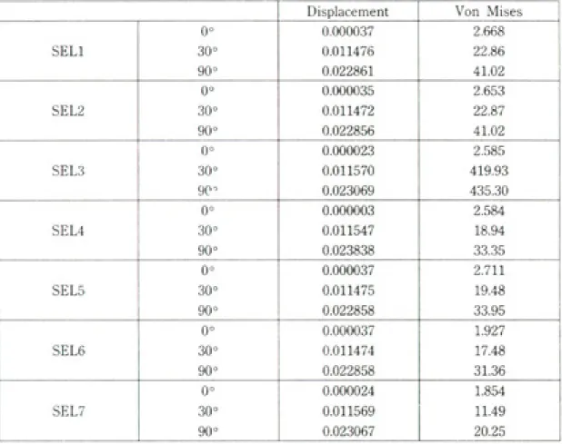
Table 4. Model과 하중에 따른 변위와 von Mises stress
다. 600㎛인 경우에는 stress가 나타나지 않으나 500㎛인 경우에는 stress가 전체적으로 분포되는 양 상을 보이고 있다. 이러한 현상은 pitch가 줄어들어 screw가 시작되는 깊이 1㎜이하의 부위 강성이 증가 하였기 때문이다. 이에 따라서 screw가 형성된 부위 에 stress가 증가한 만큼 상부 shoulder의 stress가 감소하였다.
7. Model 7
Model 7에서 즉 pitch height가 500㎛이고 shoulder diameter가 3.75㎜이며 shoulder height가 1㎜인 경우 가장 이상적인 응력분포를 나 타내었다. 즉 상부 cortical plate에 응력이 집중되지 않고 골의 전 부분에 고루 응력이 분포하였으며 상부 의 shoulder가 없어서 수직, 수평, 경사력에 모두 변 위가 적게 나타났다.(그림 8) 추후 인공치아 개발시 고정체의 형태는 이러한 설계가 바람직하다고 사료 된다.(Table 4)
Ⅳ. 총괄 및 고안
유한요소의 응력 분석을 위해 principle stress, shear stress 등이 이용될 수 있으나, 본 경우와 같 이 수직하중, 수평하중 및 경사하중의 다른 방향의 하중에 따른 응력분포의 비교를 위하여 Von Mises stress가 사용되었다.(45, 46)
임프랜트와 골 계면과의 응력분포를 유한요소로 연구할 때 두 물체의 경계 부분을 마찰력이 없는 계 면으로 설계되어야 할지, 결합된 계면으로 설계되어 야 할지 논란이 많다. 그러나 발생된 응력은 계면을 통해 골에 전달이 되어야 하고 물체의 경계부위에서 의 stress gap은 extrapolation에 의해 계산된다.
그러므로 최근 임프랜트와 골 계면과의 경계부분을 결합된 계면으로 설계하는 것이 바람직하다고 사료 되며, 본 연구도 임프랜트와 골 계면은 결합되어 응 력 전달이 되도록 설계하였다.(47)
골 은 nonhomogenous, anisotropic, viscoelastic 한 재료이나, 응력분산을 연구하기 위
한 기본 물성을 isotropic, linear, elasticity를 가졌 다고 편의적으로 가정한다. 또한 골의 인장강도는 remodeling의 발생과 반비례하여 감소한다. 그 이 유는 미성숙 Harversian canal의 공간이 강도를 감 소시키며 미성숙 Harversian canal의 결정화가 충 분히 발생되지 않아 강도를 감소시킨다. 그러므로 실 제의 골의 물성은 치유기간 및 부위에 따라 세분하여 연구하여 추후 유한요소의 연구 시에 보다 실제에 가 까운 물성치의 대입이 요구된다.
본 연구에서 임프랜트 고정체는 연결되지 않고 개 개 단위로 하중을 받았으므로 다른 연구보다 수평하 중에서 골에 큰 응력 집중현상을 보였다. 추후 임프 랜트가 상부구조로 연결될 경우, 이러한 고정체의 설 계변화가 어떻게 응력분포를 보이는지 계속적인 연 구가 필요하다고 사료된다.(48)
Ⅴ. 결 론
본 연구에서 임프랜트 고정체에 다른 세 방향의 하 중을 가하고, 임프랜트 및 골에 분포하는 응력을 연 구한 결과, 수직하중, 경사하중 및 수평하중의 순서 로 골에 응력 집중이 증가하였으며 고정체의 설계 중 3.75㎜ shoulder diameter, 1㎜ shoulder height, 0.5㎜ pitch height를 가진 임프랜트 고정체가 수직 하중, 경사하중 및 수평하중에서 가장 양호한 응력분 포를 보였으며 4.1㎜ shoulder diameter를 가진 임 프랜트 고정체가 각각의 하중에서 가장 좋지 않은 응 력분포를 보였다.
참 고 문 헌
1. Adell R, Lekholm U, Rockler B, Branemark P-I : A 15-year study of osseointegrated in the treatment of the edentulous jaw. Int J Oral Surg 6 : 387-461, 1981.
2. Albrektsson T, Semmerby L : Direct bone anchorage of oral implants : Clinical and
experimental considerations of the concept of oseointegration. Int J Prosthodont 3(1. : 30-41, 1990.
3. Albrektsson T. : Direct bone anchorage of dental implant. J Prosthet Dent 50(2) : 225-261, 1983.
4. Arthur MR, Steven AA. Peter SL, et al : Evaluation of strain terminal abutment site of a fixed mandibular implant prostheses clearing cantilever loading. J Prosthet Dent : 293-102, 1993.
5. Bergam B : Evaluation of results of treatment with osseointegrated implant by the Swedish National Board of Health and Welfare. J Prosthet Dent 50 : 114-120, 1983.
6. Bidez MW, Chen Y, Mcloughlin SW, et al : Finite element analysis of four-abutment harder bar design. Implant Dentistry : 171-176, 1993.
7. Bouchers L, and Reichart P : Three-dimensional stress distribution around a dental implant at different stages of interface development. J Dent Res 62(2) : 155-159, 1983.
8. Brunski JE : Biomechanics of oral implants : Future Research Directions, J of Dental Education : 52, 12 : 775-787, 1988.
9. Brunski JE, Hipp JA : In vivo forces on endosteal implants. A measurement system and biomechanical considerations. J Prosthet Dent 51 : 82, 1984.
10. Branemark P-I, Zarb GA, Arbrektsson T : Tissue-integrated prosthesis : Osseointegration in clinical dentistry. Chicago, Quintessence Publ Co, 1985.
11. Branemark P-I : Osseointegration and its experimental background. J Prosthet Dent 50(3) : 399-410, 1983.
12. Carlsson GE : Masticatory Efficiency : The effect of age. the loss of teeth and prosthetic rehabilitation. Int Dental Journal 34 : 93-97,
13. Carr AB, Laney WR : Maximum occlusal force levels inpatients with osseointegrated oral implant prostheses and patient with complete dentures. Int J Oral Maxillofac Implants 2(2) : 101-108, 1987.
14. Clelland NL, Lsmail YH, Zachi HS, Pepko D : Three-dimensional finite element stress anaysis in and around the Screw-Vent implant. Int J Oral Maxillofac Implants 6 : 391-398, 1991.
15. Cook SD, Klawitter JJ, Weinstein AM, Lavernia CJ : The design and evaluation of dental implants with finite element analysis. In International Conference Proceedings, Finite element in Biomechanics(Ed. simson BR). Tucson : The University of Arizona 160-178, 1980.
16. Cook SD, Klawitter JJ, Weinstein AM : A three- dimensional finite element analysis of a porous rooted Co-Cr-Mo alloy dental implants. J Dent Res 61 : 25-25, 1982.
17. Cox JF, Zarb G : the longitudinal clinical efficacy of osseointegrated dental implants : a 3-year report. Int J Oral Maxillofac Implants 2 : 91-99, 1987.
18. Craig MM, and Ismail YH : Finite element stress analysis of tooth-to implant fixed partial denture design. J Prosthet Dent 2 : 83-92, 1993.
19. Craig RG, et al : Restorative dental materials.
7th ed. St. Louis, C.V. Mosby Co. 1985.
20. David Ch, William RG, Vijay KG and John CK : Comparison of stress transmission in the IMZ implant system with polyoxymethlene or titanium intramobile element-a finite element stress analysis. Int J Oral Maxillofac Implants 7 : 450-458, 1992.
21. David MD : The role of implants in the treatment of edentulous patients. Int J Prosthodont 3 : 42- 49, 1990.
22. David DM, Zarb GA and Chao YL. : Studies on
I. The effect of varying the number of supporting abutment. Int J Oral Maxillofac Implants 3 : 197- 201, 1988.
23. David DM, Rimrott R and Zard GA : Studies on frameworks for osseointegrated pro stheses. Part
Ⅱ. The effect of adding acrylic resin or porcelain to from the occlusal superstructure. Int J Oral Maxillofac Implants 3 : 275-280, 1988.
24. Desijardins RP : Prostheses design for osseointegrates implants in the edentulous maxilla. J Oral Maxillofac Implants 7 : 311-320, 1992.
25. Ericsson I, Lekholm U, Branemark P-I, et al : A clinical evaluation of fixed bridge restorations supported by the combination of teeth and osseointegrated titanium implants. J Clin Periodontol 13 : 307-312, 1986.
26. Ferrario V, and Sforza C : Biomechanical Module of the human mandible-A hypothesis involving stabilizing activity of the superior belly of lateral pterygoid muscle. J Prosthet Dent 68 : 829-835, 1992.
27. French AA, Bowles CQ, Parham PL, et al : Comparison of peri-implant stresses transmitted by four commercially available osseointegrated imolants. Int J Perio and res 9 : 221-230, 1989.
28. Glickman I, Roeber FW, Brion M, Fameijer JHN : Photoelastic analysis of internal stresses in the periodontium created by occlusal forces. J Periodont 41 : 615-619, 1970.
29. Haraldson T, Carlsson GE : Bite force and oral function in patients with osseointegrated oral omplants. Scand J Dent Res 85 : 200-208, 1977.
30. Haraldson T, Jemt T, Stalblad PA, Lekholm U : Oral Function in subjects with overdentures supported by osseointegrated implants. Scand J Dent Res 16 : 385-409, 1988.
31. Huiskes R, Chao EYS : A survey of finite element analysis in orthopedic biomechanics : The first
decade. J Biomech 16 : 385-409, 1983.
32. Ismail YH, Pahountis LN, Fleming JF : Comparison of two-dimensional finite element analysis of a blade implant 4, 25-31, 1987.
33. Kevser AA, Erman AT : Stress induced by different loaning around weak abutments. J Prosthet Dent 68 : 879-994, 1992.
34. Kim DW, Kim YS : A study on the osseointegrated prostheses using three dimensional finite element method. J of Korean Academy of Prosthodontics 29(1) : 167-167, 1991.
35. Kim JE, Cho IH : Finite element analysis of stresses induced by esthetics restorations in osseointegrated implant. KAID 12(1) : 23-40, 1992.
36. Kinni ME, Hokama SN, Caputo AA : Force transfer by osseointegration implant devices. Int J Oral Maxillofac Implants 2 : 11-14, 1987.
37. Ko CC, Kohn DH, Holloster SJ : Micromechanics of implant / Tissue interface. J Oral Implantol 18(3. : 220-230, 1992.
38. Kregzdem : A method of selecting best implant prostheses design option using three- dimensional finite element analysis, Int J Oral Maxillofac Lmplants 8 : 662-673, 1993.
39. Lavernia CJ, Cook SD, Klawitter JJ, and Weisten AM : The sffsct of implant elastic modulus on the stress distribution surrounding dental Implants, International conference preceedings, finite element I biomechanics(Ed. Simmon BR). The University of Arizona, Tucson 179-182, 1980.
40. Lavernia CJ, Cook SD, Klawitter JJ, Weistein AM : An analysis of stress in a dental implant system. J Biomech 14(8) : 555-560, 1981.
41. Lawrece AW : The biomechanics of force distribution in implant-supported prostheses. Int J Oral Maxillofac Implants 8 : 19-31, 993.
42)Meijer HJA, Kuiper JH, Starmans FJM, Bosman F : stress distribution around dental implant-
influence of superstructures, length of implant and height if mandible. J Prosthet Dent 68 : 96- 102, 1992.
43. Meijer HIJ, Starmans FJM, Sten WHA and Bosman F : A three-dimensional finite-element analysis of bone around dental implants in a edentulous human mandible. Archs oral Biol 38(6. : 491-496, 1993.
44. Moon BH, Yang JH : study on the stress analysis of three root-form implants with finite element analysis. KAID 12(1) : 116-137, 1992.
45. Rieger MR, Adams WK, Kinzel GL, Brose MO : Finite element analysis of bone-adapted and
bone-bonded endoseous implants. J Prosthet Dent 62 : 436-440, 1989.
46. Rieger MR, Mayberry M : Finite element analysis of six endosseous implants. J Prosthet Dent 63 : 671-676, 1990.
47. Simon BR, Woo SLY, Stanley GM, et al : Evaluation of one-two-and three-dimensional finite element and experimental models of internal fixation plates. J Biomech 1977.
48. Williams KR, Watson CJ, Murphy WM, Scott J, Gregory M, Sinobad D : Finite element analysis of fixed prosthesis attached to osseointegrated implant. Quintessence 21 : 563-570, 1990.
논문사진 부도설명
그림 1. 고정체 상부 2mm와 하부 2mm는 피질골에 위치되어 bicortical fixation을 부여하였다. 골과 고정체는 계면을 따라 고정된 결합으로 가정하였고 고정체는 악골의 중앙에 위치시켰다.
그림 2. 수직하중의 경우에는 임프랜트의 지름이 변화되기 전까지의 나사들은 거의 고르게 힘을 받고 있으며 응 력의 최대치는 나사가 줄어드는 부분에서 발생하고 있다.
그림 3. 수평하중의 경우 임프랜트 상단 머리부분에 응력이 집중되어 있고 임프랜트 방향을 따라 조금씩 감소하 고 있다.
그림 4. 30도 하중의 경우는 두 하중이 복합되어 가해지는 경우이다. 응력의 분포를 보면 수평하중의 경우와 거 의 비슷한 양상을 보이고 있다. 전체적으로 보면 수평하중의 경우에는 머리부분에서 가장 큰 응력이 발생 하고 있다.
그림 5. Model 2는 Model 1의 하단에 hole을 뚫은 모델이다. 수직하중의 경우에는 응력분포가 나사가 줄어드는 부위와 hole이 제일 윗부분으로 더 몰리고 있다.
그림 6. Model 3은 임프랜트의 머리부분의 직경을 나사의 직경과 동일하게 줄인 모델이다. 해석결과를 보면 수 평하중에서 상당한 응력개선이 나타나고 있다. 최대응력이 발생하는 부위가 상당히 넓어졌다.
그림 7. Model 5는 Model 1의 pitch height을 700㎛으로 바꾼 것이다. 나사부분에서는 응력이 크게 나타나지 않고 shoulder에 응력집중이 발생하므로 증가된 pitch height는 응력 분포에 큰 영향을 미치지 않는다.
그림 8. Model 7에서 즉 pitch height가 500㎛이고 shoulder diameter가 3.75mm이며 shoulder height가 1mm인 경우 가장 이상적인 응력분포를 나타내었다. 즉 상부 cortical plate에 응력이 집중되지 않고 골 의 전 부분에 고루 응력이 분포하였으며 상부의 shoulder가 없어서 수직, 수평, 경사력에 모두 변위가 적 게 나타났다.
그림. 1
그림. 3
그림. 5
그림. 2
그림. 4
그림. 6
사진부도
=Abstract=
A THREE DEMENTIOAL FINITE ELEMENT ANALYSIS OF THE EFFECT OF SEVEN IMPLANT DESIGNS
ON STRESS DISTRIBUTION
S.J. HEO*, C.H. HAN**,J.P. Chung***
*Dep. Of Prosthodontics,College of Dentistry, Seoul National University
**Dep. Of Prosthodontics,College of Dentistry, Yonsei University
***Dep. Of Prosthodontics,College of Dentistry, Seoul National University
Introduction
Stress or strain-induced bone remodeling is an important response in unctional adaptation of bone around implants. The overload on the implants can cause the pathologic bone resorption and results in the implant failure. The purpose of this study was to investigate the stress magnitudes and distributions at the bone/implant interface in seven different analysis.
M : Model, OD : Outer diameter(㎜), ID : Inner diameter(㎜), L : Length(㎜), PH : Pitch height(㎜), SD : Shoulder diameter(㎜), SD : Shoulder diatmeter(㎜), SH : Shoulder height(㎜), BH : Bottom hole. N : No, Y : Yes
The bone models were 10mm high consisting of 2mm bicortical outer parts and 6mm cancellous inner part. The gold crown with titanium abutment connected to the implants to stimulate the implant prothesis in clinical situations. The total number of elements used in the largest FEM was 14410. The material prioperity values assignd in this study were made on the basis of previous published data. The load of 20Kg was given to each model at 0 o, 30 o, 90 o, direction. The finite element models wre generated and solved by using a computer-aided engineering program(I-DEAS, Structural Research Dynamics(Co). This pakage was installed on a SGI Indigo II 64-Mbyte main computer.
Material and Mathods
Seven different implant designs were used in this study.