Nicalon/CAS 세라믹 복합재료의 인장특성
김정국† · 김원경*
Tension Behavior of Nicalon/CAS Ceramic Composites
Jeongguk Kim and Weon-Kyong Kim
Key Words : Ceramic Composites (세라믹복합재료), Tensile Testing (인장시험), IR Thermography (적외선 서모그래피), Fracture Mechanisms (파괴메카니즘)
Abstract
The tension behavior of Nicalon/CAS glass-ceramic matrix composites was investigated. Infrared (IR) thermography was employed for two different types of Nicalon™/CAS composites, i.e., cross-ply and unidirectional specimens. During tensile testing, an IR camera was used for in-situ monitoring of progressive damages of Nicalon™/CAS samples. The IR camera provided the temperature changes during tensile testing. Microstructural characterization using scanning electron microscopy (SEM) was performed to investigate the fracture mechanisms of Nicalon™/CAS composites. In this investigation, the thermographic NDE technique was used to facilitate a better understanding of the fracture mechanisms of the Nicalon™/CAS composites during tensile testing.
1. Introduction
Ceramic-matrix composites (CMCs) have evolved as one of the potential candidates for high-temperature structural applications, such as aircraft structures, fusion reactors, and heat-management systems, due to their lightweight, high-temperature resistance, and a balance of toughness and strength [1-3]. To encourage wide applications of CFCCs, nondestructive evaluation (NDE) of CFCCs is required for assuring manufacturing quality and lifetime service applications. NDE can also be used as a characterization means for the research and development of advanced materials, although not much attention has been addressed so far.
Infrared (IR) thermography is a possible NDE method for the characterization of CFCCs. This technique is based on the concept that after applying a uniform heat pulse to the sample surface, a localized disruption of the heat flow will occur where defects and/or flaws are present. The change in the heat flow translates into temperature differences on the material surface [4-6]. The temperature variations on the surface
of a sample were used to create thermographic images in terms of either temperature difference or thermal diffusivity. However, in this study, the IR thermography was used to measure the temperature changes and in-situ monitoring of temperature evolution of CFCC samples during tensile tests [4-10].
Relatively little work has been performed on the investigation of micromechanisms of fracture in CFCCs using NDE techniques [11]. In this research, a NDE technique, IR thermography, was utilized to characterize the fracture behavior of CFCCs during monotonic tensile loadings. Thus, the main objectives of this investigation on NDE and tension behavior of Nicalon™/CAS are to (1) investigate the tension behavior of Nicalon™/CAS composites with the aid of a NDE technique, (2) explore failure mechanisms in Nicalon™/CAS composites with the aid of IR thermography and SEM methods, and (3) provide fracture and NDE information to aid in the fabrication, development, and selection of Nicalon™/CAS composites for structural applications.
2. Materials Systems and Experimental Procedures
† 한국철도기술연구원
E-mail : [email protected]
TEL : (031)460-5518 FAX : (031)460-5509 * 한국철도기술연구원
2.1 Materials
Continuous ceramic fiber reinforced ceramic matrix composites were used in this investigation, i.e.,
continuous Nicalon™ fiber-reinforced calcium aluminosilicate (CAS) glass-ceramic matrix composites, designated as Nicalon™/CAS (manufactured by Corning Glass Works, Corning, NY). Nicalon™ is an amorphous/crystallite continuous ceramic fiber, predominantly SiC, with a diameter of approximately 10 to 15 µm, and has a chemical composition of 59% Si, 31% C, and 10% O2 by weight.
The composites were fabricated by Corning Glass Works using the hot-pressing technique. The matrix material, CAS (CaO-Al2O3-2SiO2), is a family of refractory alkaline earth aluminosilicate glass-ceramics developed in the pseudo-binary system of triclinic anorthite (CaO-Al2O3-2SiO2) [12]. Two types of materials were prepared in this investigation: a [0/90]4S
cross-ply composite panel and [0]12 unidirectional composite panel. This material was produced by the hot- pressing method at approximately 1,350°C. Dog-bone type flat tensile coupons were machined from as- received Nicalon™/CAS panels. Each coupon was machined with a diamond saw at a moderate operating speed in order to avoid the creation of machining- induced damages.
2.2 Tensile Testing and Mechanical Characterization Monotonic tensile tests were conducted using a computer-controlled Material Test System (MTS) 810 servohydraulic frame equipped with hydraulic grips.
Since CFCCs show inherent brittleness, the precise specimen alignment is critical to avoid damage from concentric and angular misalignments.
The testing data was obtained using a TestStar™ IIs data-acquisition system. The tensile tests were conducted at room temperature under a displacement control at a cross-head speed of 0.3 mm per minute according to the ASTM guideline. In this study, dog-bone type flat specimens were used to determine the ultimate tensile strength and stiffness of the Nicalon™/CAS composites and to investigate the damage evolution during the tests.
An IR camera was used for in-situ monitoring of the temperature change during tensile testing. Aluminum tabs were attached with epoxy glue at each side of the shoulder section of the coupon in order to avoid rupture of the grip parts during loading the sample.
Optical microscopy (OM) and SEM were used to characterize both the fracture surface and interlaminar microstructure. SEM was employed to study the fracture mechanisms of CFCC coupons during tensile tests.
3. Results and Discussion
3.1 Tensile Behavior of Nicalon/CAS Composites Figure 1 presents the tensile testing results of the stress-strain behavior for both cross-ply and unidirectional Nicalon™/CAS composites, respectively.
In Fig. 1, several mechanical properties of
Nicalon™/CAS composites were determined, including proportional limits, elongations, and ultimate tensile strength (UTS) values. The proportional limits and UTS values of the unidirectional composites showed much higher values than those of the cross-ply composites.
The average value of UTS was about 180 MPa and 250 MPa for cross-ply and unidirectional composites, respectively. Unidirectional composites showed a proportional limit of 100 MPa, while the proportional limit of the cross-ply composites was 60 MPa. Those characteristics are mainly due to different lay-ups of the laminate, i.e., the longitudinal ply presents a much higher strength value than the transverse laminate.
In Fig. 1, for the cases of the unidirectional composites, similar trends among the composites tested have been obtained. Most of the unidirectional composites show an eminent ‘graceful failure’ mode following the proportional limit and UTS regions, which indicates the final fiber failure with extensive fiber pullout. However, the cross-ply composites showed the
‘graceful failure’ only after the proportional limit. The
‘graceful failures’ after reaching UTS were not shown, which are directly related to the lack of fiber pullout.
This phenomenon will be discussed at the microstructural characterization section.
The cross-ply composites samples, 24-14 and 16, were selected for further investigation on the relationship between the NDE signatures and mechanical performance during tensile testing. In unidirectional composites, the samples, 25-6, 8, and 9, were used in this investigation.
0 1 2 3 4 5 6
0 50 100 150 200 250 300 350
(100 MPa)
[0]12 Unidirectional Composites
Fig. 1. Tensile behavior of [0/90]4S cross-ply and [0]12
unidirectional Nicaon™/CAS composites.
3.1.1. Temperature Evolution during Tensile Testing In order to monitor the damage evolution in terms of temperature change during tensile tests, an IR camera was employed to record temperature change. Generally, temperature increases were observed during mechanical
[0/90]4S Cross-ply Composites
Proportional Limit (60 MPa)
24-14 24-15 24-16 25-6 25-8 25-9 25-11
Stress (MPa)
Strain (%)
testing due to the frictional heating between the fiber and matrix, and the energy absorption mechanisms, including interfacial debonding, delaminations, and fiber pullout.
3.1.2. Cross-ply Nicalon™/CAS composites
Figure 2 presents the relationship between the stress and temperature change during tension tests for the cross-ply Nicalon™/CAS composites.
In Fig. 2, as a rule, no significant temperature changes have been observed during tensile testing, but temperature peaks have been obtained at the time of failure. After the normalization of the temperature with respect to the initial temperatures of both samples, quite large amounts of temperature increases at failure were obtained for both cross-ply composites, as presented in Fig. 2. Although there were some temperature variations during tensile testing for both samples, it is difficult to interpret the exact reason for this phenomenon. Since the maximum load values were quite small during tensile testing, no eminent thermoelastic effects have been observed for cross-ply sample 24-16, as shown in Fig. 2.
However, there is a slight temperature drop from the beginning of the test in sample 24-14, and this is mainly due to the thermoelastic effect. In terms of the temperature increase at the time of fracture, it could be inferred that the frictional forces and/or interfacial interactions between the fiber and matrix could affect the temperature change during the test.
Fig. 2. Stress vs. temperature evolution during tensile testing for cross-ply Nicalon™/CAS composites.
Figure 2 also shows a direct comparison between the stress-strain behavior and temperature evolution behavior during monotonic tensile testing. Note that the speed of the IR camera was 7 Hz for both samples. The individual data points in Fig. 2 indicate one frame of IR image, i.e., every frame was obtained every 1/7 second (about 0.143 second). The number of frames at the time of failure in Fig. 2 shows more than 6 frames for the sample 24-16, and more than 15 frames for the sample 24-14. This means that the failures of the cross-ply Nicalon™/CAS composites were achieved by more fiber pullout at the
time of failure, which indicates the toughening mechanisms in the composites.
0 100 200 300 400
0 50 100 150 200 250 300 350
Time (Sec)
25-6 25-8 25-9
Stress (MPa)
0 2 4 6 8
25-8 25-9
Fig. 3. Stress vs. temperature evolution during tensile testing for unidirectional Nicalon™/CAS composites.
In Fig. 2, both cross-ply samples exhibit the temperature peaks, especially, at the time of failure.
From these results, it is understandable that the main temperature changes for the cross-ply Nicalon™/CAS composites during tensile testing seem to result from the final fiber pullout. The fiber pullout at the final moment of failure generates severe frictional heating between the fiber and matrix, and the temperature increases seem to be developed from the final fractures of fibers, as further discussed later.
3.1.3. Unidirectional Nicalon/CAS Composites
Figure 3 presents the stress response versus temperature evolution during tensile testing for the unidirectional Nicalon™/CAS composites. Like cross- ply Nicalon™/CAS composites, very similar trends have been presented, i.e., no severe temperature changes from the beginning of the test have been observed, but the temperature peaks, especially at the time of failure, have been obtained for all samples. The temperature variations before failures were not so significant for all unidirectional samples. However, temperature peaks were obtained at the time of fracture.
In Fig. 3, the similar results also have been obtained, as compared with the cross-ply composites. However, the stress-strain behavior for unidirectional composites shows a ‘graceful failure’ after reaching UTS for all samples in Fig. 3. Regardless of the presence of a graceful period following the attainment of UTS, the temperature peaks have been found only at the time of failure, as shown in Fig. 3. From these results, it is suggested that the fiber pullout and consecutive failure of fibers during the graceful period do not generate significant temperature increases.
3.2. Microstructural Characterization of Tensile-Tested Nicalon/CAS Composites
25-6 3.6oC 25-9
25-8
25-6
1.6oC 1.3oC
Temperature Change (∆T,o C)
∆T-Time Stress-Time
25-6 25-8 25-9
0 100 200 300
0 40 80 120 160 200 240
24-16 24-14 24-16
24-14
Temperature Change (∆T,o C)
Stress (MPa)
24-14 24-16
Time (Sec)
0 2 4 6
4.1oC 2.1oC
∆T-Time Stress-Time
24-14 24-16
3.2.1 Cross-ply Nicalon/CAS Composites
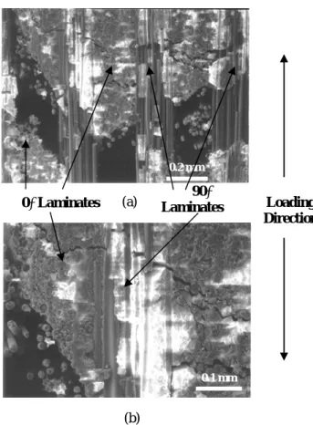
The microstructural characterization was conducted on the tensile-tested Nicalon™/CAS composites using SEM. Figure 4 shows the entire cross section of the failure surface of the cross-ply Nicalon™/CAS composite. The 90° laminate fiber bundles seem to hold together due to the extensive fiber pullout of fiber bundles, but 0° laminates were all broken with entire separation. Actually, the 90° laminate fiber bundles are also completely broken. Figure 4 also presents the failure mode in the cross-ply composites. The fiber pullout and fracture of the 90° laminate provides the final step of fracture in this composite.
Figure 5 presents a more detailed failure mode of the cross-ply Nicalon™/CAS composites. First, there were debonding and failure within the 0° laminate. Then, the crack propagated into the 90° laminate, and the final failure occurred in the 90° laminate with extensive fiber pullout.
In this situation, the 90° laminate fiber bundle plays a role to delay the load for catastrophic failure, as shown in Fig. 5(b). The final rupture was achieved by the fiber pullout of the 90° laminate bundle, as presented in Fig.
5(a).
Fig 4. The entire cross section of the failure surface.
3.2.2 Unidirectional Nicalon/CAS Composites
The [0]12 unidirectional Nicalon™/CAS composites showed somewhat different failure modes, as compared with the cross-ply composites. The tensile behavior also exhibited different trends in the values of the proportional limits and UTS. The unidirectional composites presented a much higher tensile strength value of 250 MPa than 180 MPa for the cross-ply composites. This is mainly due to the different lay-up of laminates. Generally, the unidirectional composites have somewhat higher tensile strength than the cross-ply composites.
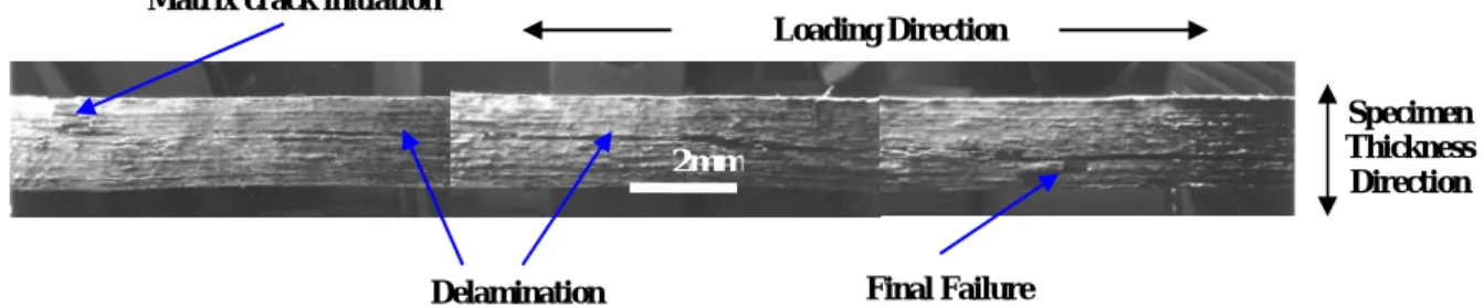
Figure 6 presents the cross-sectional view of the fracture surface for the entire gage length. The failure mode in the unidirectional composites showed extensive amounts of delamination along the loading direction, as shown in Fig. 6. In the cross-sectional view (Fig. 6), the initial matrix cracking and delamination throughout the
gage section were observed. The final failure includes massive multiple matrix cracking due to the final fiber pullout.
(b)
Fig. 5. Failure modes of cross-ply Nicalon™/CAS composites: (a) lower magnification and (b) higher magnification; debonding and failure of the 0° laminate, crack propagation to reach the 90° laminate, and final fiber pullout in the 90° laminate.
Figure 7 shows the fiber failure and/or pullout and delamination after initial matrix cracking. The delamination, probably between each ply, becomes a dominant mechanism to transfer the applied load of composites after initial matrix cracking and crack propagation.
The load transfer was accomplished through the delamination. Figure 8 presents the deflection of cracks along the delamination direction with the propagation of matrix cracking, followed by fiber breakage and/or pullout within a ply. The deflection of the crack along the delamination direction could be attributed to the presence of internal flaws or defects although the SEM micrograph in Fig. 8 does not provide the eminent defect.
The final failure was accomplished by further crack propagation with extensive matrix cracking and additional deflection of the cracks along the delamination, followed by final fiber pullout.
The summary of failure modes in the unidirectional composites is provided in Fig. 9. The initial surface or the sub-surface matrix cracking with debonding at the
500µ m
90° Laminate
Loading Direction
0° Laminate
0.1 mm 0.2 mm
0° Laminates 90°
Laminates Loading Direction (a)
fiber and matrix interface can be the first step of failure mechanisms. The tensile load can transfer along the weak interface between plies (delamination). Then, further interfacial debonding at each ply or laminate could occur. The final failure is accomplished by fiber pullout with massive surface matrix cracking.
3.3. Remarks on Tensile Fracture Behavior and NDE Signatures
Although both Nicalon™/CAS composites exhibited the temperature peaks at the time of failure, the final fracture behavior was different; the unidirectional composites showed a graceful failure mode following the attainment of UTS, while the final failures of the cross- ply composites occurred at UTS. Due to the characteristics of the laminates stacking structure, the unidirectional composites showed much higher tensile strength values than the cross-ply composites. However, the cross-ply composites presented somewhat higher values of the temperature increases at the time of fracture than the unidirectional composites. At this point, it is understandable that the temperature increase at the time of failure could be related to microstructural characteristics, such as delamination, fiber debonding, pullout and fiber breakage, i.e., fracture mechanisms or failure modes. Substantially, the SEM characterization results showed the difference in failure modes between both composites. In Fig. 4, the fracture behavior of the cross-ply composites was provided, and the final rupture was achieved by fiber pullout and final fiber breakage in all 90° laminates after complete collapse of the 0°
laminates. However, in the case of the unidirectional composites, the final failure occurred by fiber pullout and further delamination from a part of the unidirectional laminates, as shown in Fig. 6. In other words, the final failure of the unidirectional composites was achieved by a kind of dispersive failure after a graceful failure period, while the cross-ply composites provided relatively instant failure at the highest tensile strength. Through this interpretation, the cross-ply composites showed somewhat greater values of frictional heating at the time of failure than the unidirectional composites.
4. Conclusions
The tensile properties of the Nicalon™/CAS composites were investigated with the aid of a thermographic nondestructive evaluation (NDE) technique. In the cross-ply Nicalon™/CAS composites, the final failure occurs at the ultimate tensile strength, and significant temperature increases have been observed at the time of failure. The stress-strain behavior for the unidirectional Nicalon™/CAS composites showed a clear
‘graceful failure’ after reaching UTS for all samples.
Regardless of the presence of the graceful period after reaching UTS, the temperature peaks have been found only at the time of failure. From these results, it is suggested that the fiber pullout and consecutive failure of fibers both at UTS and during the graceful period do not generate significant temperature increases.
In the cross-ply Nicalon™/CAS composites, the crack seems to initiate at the largest flaw within the 0°
laminate at the load level above the proportional limit.
The initiated cracks experience the crack propagation with debonding between the fiber and matrix interface at the 0° laminate. At this point, further crack propagation occurs in the 0° laminate, and there are delaminations between the 0° and 90° laminates. The final rupture can be accomplished in the 90° laminate with fiber debonding, followed by the extensive fiber pullout.
In the unidirectional Nicalon™/CAS composites, the initial surface or sub-surface matrix cracking with debonding at the fiber and matrix interface can be the first step of failure mechanisms. The tensile load can transfer along the weak interface between plies (delamination). Then, further interfacial debonding at each ply or laminate could occur. The final failure is performed by fiber pullout with massive surface matrix cracking.
Acknowledgments
This work is supported by the National Science Foundation to the University of Tennessee, Knoxville.
The authors would like to thank Prof. Peter Liaw for his guidance and support.
References
1. R.L. Lehman, S.K. El-Rahaiby, and J.B. Wachtman, Handbook on Continuous Fiber-Reinforced Ceramic Matrix Composites,The Am. Ceram. Soc., 1995, p.
495.
2. K.K. Chawla, Ceramic matrix Composites, Chapman & Hall, London, 1993, p. 4.
3. P.K. Liaw, Fiber-Reinforced CMCs: Processing, Mechanical Behavior and Modeling, JOM, October 1995, p. 38.
4. Nondestructive Testing Handbook, 2nd ed., Vol. 10, Nondestructive Testing Overview, S. Ness, C. N.
Sherlock, P. O. Moore, and P. M. McIntire, American Society for Nondestructive Testing, Inc., 1996.
5. ASM Handbook: Nondestructive Evaluation and Quality Control, Vol. 17, (ASM International, 1992), p. 231.
6. J. Kim, P.K. Liaw, J.J. Hwu, H. Wang, and Y. Lee, Thermal and Mechanical Characterization of Ceramic Matrix Composites by Nondestructive Evaluation (NDE) Techniques, Advances in Ceramic Matrix Composites VI, Edited by J. P. Singh, N. P.
Bansal, and E. Ustundag, Ceramic Transactions, Vol.
124, The American Ceramic Society, 2001, pp. 241- 252.
7. P.K. Liaw, H. Wang, L. Jiang, B. Yang, J.Y. Huang, R.C. Kuo, and J.G. Huang, Scripta Mater., 42, 2000, p. 2000.
8. H. Wang, L. Jiang, P.K. Liaw, C.R. Brooks, and D.L.
Klarstrom, Metallurgical and Materials Transactions, 31A, 2000, p. 1307.
9. L. Jiang, H. Wang, P.K. Liaw, C.R. Brooks, and D.L.
Klarstrom, Metallurgical and Materials Transactions, 32A, 2001, p. 2279.
10. B. Yang, P.K. Liaw, H. Wang, L. Jiang, J.Y. Huang, R.C. Kuo, and J.G. Huang, Materials Science and Engineering, A314, 2001, p. 131.
11. P.K. Liaw, D.K. Hsu, N. Yu, N. Miriyala, V. Saini, and H. Jeong, Acta Metal. et Mater., 44 (5), 1996, p.
2101.
12. S.S. Lee and W.W. Stinchcomb, Damage Mechanisms and Fracture Modes in Nicalon/CAS-II Laminates, Key Engineering Materials, Vols. 121- 122, 1996, p. 227.
Matrix crack initiation
Loading Direction
Specimen Thickness Direction 2mm
Final Failure Delamination
Fig. 6. The cross-sectional (along the through-thickness direction of the coupon) view of the fracture surface along the entire gage length in unidirectional Nicalon™/CAS composites.
Fig. 7. Fiber broken/pullout and delamination after initial matrix cracking.
Fig. 8. The deflection of a crack (arrow) along with the delamination direction accompanied by the growth (propagation) of matrix cracking, followed by fiber breakage/pullout within a ply.
Fig. 9. Failure mechanisms in [0]12 unidirectional Nicalon™/CAS composites.
1. Matrix cracking
2. Debonding fiber/matrix
3. Load transfer along the weak interface (delamination) 4. Further interfacial debonding and delamination 5. Fiber pullout
Loading Direction 0.2 mm
0.5 mm Deflection
Delamination Loading
![Fig. 1. Tensile behavior of [0/90] 4S cross-ply and [0] 12](https://thumb-ap.123doks.com/thumbv2/123dokinfo/5208141.354370/2.892.448.809.712.978/fig-tensile-behavior-s-cross-ply.webp)