반도체디스플레이기술학회지 제19권 제4호(2020년 12월)
Journal of the Semiconductor & Display Technology, Vol. 19, No. 4. December 2020.
Assessment of Air Flow Misalignment Effects on Fume Particle Removal in Optical Plastic Film Cutting Process
Kyoungjin Kim
*and Joong-Youn Park
*†*†
Department of Mechanical System Engineering, Kumoh National Institute of Technology
ABSTRACT
Many types of optical plastic films are essential in optoelectronics display unit fabrication and it is important to develop high precision laser cutting methods of optical films with extremely low level of film surface contamination by fume particles. This study investigates the effects of suction and blowing air motions with air flow misalignment in removing fume particles from laser cut line by employing random particle trajectory simulation and probabilistic particle generation model. The computational results show fume particle dispersion behaviors on optical film under suction and blowing air flow conditions. It is found that suction air flow motion is more advantageous to blowing air motion in reducing film surface contamination outside designated target margin from laser cut line. While air flow misalignment adversely affects particle dispersion in blowing air flows, its effects become much more complicated in suction air flows by showing different particle dispersion patterns around laser cut line. It is required to have more careful air flow alignment in fume particle removal under suction air flow conditions.
Key Words : Optical Plastic Film, Laser Cutting, Fume Particles, Suction and Blowing Air Flow, Particle Simulation
1. Introduction
1Modern optoelectronics display unit fabrication requires various kinds of thin optical plastic films for manufacturing of optoelectronics devices such as thin-film transistor-driven active matrix liquid crystal display devices and active matrix organic light-emitting display devices as well as recent flexible mobile displays [1,2]. These optical plastic films are made of many different polymeric materials and they possess many novel film qualities [3].
Due to rapid growth of commercial demands for various optoelectronics display devices, it is important to develop many high-precision film processing techniques for optical plastic films, as one of them would be a fast and clean non- contact line cutting of large sized optical plastic film sheets into pre-determined dimensions in mass manufacturing of display units. The high-speed line cutting process of thin plastic films commonly uses CO
2lasers on highly
†
E-mail: [email protected]
automated large film sheet transport and positioning tables, since CO
2laser could provide several advantages such as extremely narrow kerf width, smooth and flat cut finish without subsequent cleaning operation, and relatively small thermal distortion [4-6].
Although CO
2laser cutting is relatively clean process compared to conventional forms of film cutting methods, it also inevitably generates fume particles from cutting lines due to melt shearing, vaporization, and material degradation of plastic film material in laser cuts [6]. These fume particles would land on film and it may be quite difficult to remove particle contamination.
Thus, it is very important to understand fume particle
dispersion on film surface in laser cutting of thin optical
plastic films. A previous theoretical study [7] established
numerical modeling of fume particle dispersion from laser
cutting line onto optical film surface in a quiescent air
environment. Meanwhile, the other study [8] analyzed the
downward and upward air motion effects on fume particle
dispersion and film surface contamination in a laser film
Kyoungjin Kim · Joong-Youn Park 52
Fig. 1. Schematic of fume particle removal by air flow in optical plastic film cutting process.
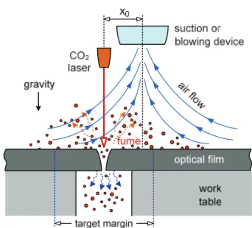
cutting process. However, rather idealistic process situations were simulated and examined in those existing studies. One notable concern raised recently in optoelectronics manufacturing industries about optical film processing would be the increase of fume particle contamination possibly by imperfect alignment between air flow motions and laser cutting line, as illustrated in Fig. 1. Therefore, the present study investigates how the misalignment of air suction or blowing motions affects fume particle dispersion and surface contamination on optical film.
2. Fume Particle Dispersion Simulation Model
The process problem of air flow misalignment in laser cutting is shown in Fig. 1 and explained as follows. The fume particles generated and ejected upward from laser film cutting line of optical plastic films. They will disperse and land on film surface causing film surface contamination and degradation. Thus, the cutting process generally requires some form of particle removal by air flow motion in form of blowing or suction [9].
Previous study [8] modeled the air flow simply as the stagnation air motions. It would be ideal to align the air flow motions into the laser cut line. However, it could be quite difficult to achieve a perfect alignment. Thus, it is expected to have some degree of misalignment, which is described as x
0in Fig. 1.
This study employs the particle dispersion model developed previously [7,8] and also assumes spherical fume particles of all sizes. Transient trajectory for each fume
particle of spherical diameter d
punder a given air flow motion u are governed by the following Basset-Boussinesq- Oseen model [10].
(1)
(2)
where r(t) and v(t) are transient location and velocity of a fume particle in two-dimensional domain over the film surface across laser cut line, respectively. The vector g is gravity on particles. Also, ρ
sand ρ
fare the mass densities of fume particle and air, respectively, while μ
frepresents dynamic viscosity of air. The details of those particle motion modeling are described in references [8,10].
The flow velocity vector of nonviscous stagnation air motion u gives its components in horizontal and upward vertical directions from laser cut line as u
x= K(x-x
0) and u
y= -Ky by considering the air flow misalignment. The stagnation flow constant K describes the flow strength and direction of blowing or suction. Since the reference point of air flow does not coincide with the laser cut line, we expect the non-symmetric particle dispersion over the film surface in this investigation.
The drag coefficient C
don a micron-sized particle of spherical shape moving in a fluid stream is usually given as semi-empirical functions of Reynolds number (Re
d= ρ
f|v-u|
d
p/ μ
f). As stated in previous studies [8-11], the following equation should be adequate for calculating viscous drag on the fume particles up to Re
d< 1,000.
(3)
Transient fume particle trajectories of a given particle size can be calculated by solving Eqs. (1) and (2) with particle drag model of Eq. (3), once the ejection velocity and angle from laser cut line are known.
3. Results and Discussion
The fume particle dispersion model for laser cutting and r v
dt d
t f f p f s p
f d p f
s p
t d d d d
d
d C dt d d
) ( 2
) 3 6 (
) 8 (
2 ) 6 (
2 3
2 3
u g v
u v u v v
) Re 158 . 0 1 Re (
24
2/3d d
C
d
Assessment of Air Flow Misalignment Effects on Fume Particle Removal in Optical Plastic Film Cutting Process 53
Fig. 2. Fume particle dispersion patterns by blowing and suction air flow motions compared to no air flow cases for different particle size of 15, 30, 60 µm.
subsequent particle trajectory simulations investigate random dispersion of fume particle from laser cutting in blowing and suction air flow motions and particle contamination onto the optical film surface with the effects of air flow misalignment. It is difficult to obtain or even well understand exact fume particle ejection behavior in laser cutting at this point. Thus, similar to previous study [8], this numerical investigation also use the probabilistic fume particle generation model derived from experimental
observation and measurements in laser materials processing [12,13] for a series of random fume particle simulations.
Here we assume the probability distributions of particle
ejection velocity in lognormal distribution form with mean
of 1 m/s and standard deviation of 1 m/s. Secondly, fume
particle ejection angle is in normal distribution with mean of
zero degree (meaning upward vertical direction) and
standard deviation of 25 degrees. Probabilistic distribution
of fume particle diameter is modeled into lognormal
Kyoungjin Kim · Joong-Youn Park 54
distribution with mean of 12 µm and variance of 100 µm
2by considering particle size distribution measurements in laser materials processing tests [12].
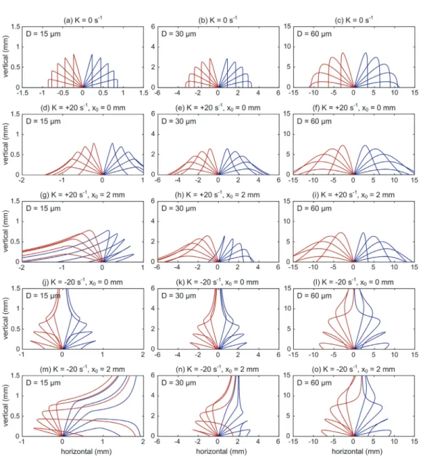
Before presenting the results of random fume particle simulations, the effects of air flow misalignment in laser cutting on fume particle behaviors are first shown in Fig. 2 for three fume particle diameters of 15, 30, and 60 µm. Each figure in Fig. 2 contains particle trajectories over optical film for particle ejection angles of -75, -60, -45, -30, -15, 15, 30, 45, 60, and 75 degrees with ejection velocity of 1 m/s. Figs.
2(a), (b), and (c) in first row show the cases without any air flow motion in order to be compared with the air flow misalignment cases.
The particle trajectories in second and third rows of Fig. 2 are the cases of blowing air motions (positive K). The effects of air flow misalignment (x
0= 2 mm) shown in Figs. 2(g)-(i) can be appreciated in comparison with cases of perfect air flow alignment shown in Figs. 2(d)-(f). While blowing air motion generally disperses fume particles farther from laser cut line, the observation shows air flow misalignment further increases particle dispersion and film surface contamination, especially for smaller fume particles.
At this time, fourth and fifth rows of Fig. 2 provide particle trajectories for suction air flow with negative K.
Here also similarly, the cases of air flow misalignment (x
0= 2 mm) in Figs. 2(m)-(o) are compared with cases of perfect air flow alignment in Figs. 2(j)-(l). Air flow motions of suction are generally beneficial to particle removal either by upward particle suction or preventing particle dispersion from laser cut line.
If suction air flow is misaligned in suction motion, its effects are more complicated than blowing air flow cases.
The larger particles of 60 µm diameter show relatively small difference in particle trajectories due to air flow misalign- ment. In contrast, smaller fume particles such as 15 or 30 µm diameter exhibit significantly high level of dispersion from laser cut line for lower ejection angles.
From now on, the computational results of random fume particle trajectory simulations will be presented in order to assess the overall film surface contamination due to air flow misalignment, since actual laser cutting of optical film process generates fume particles of wide range of different sizes with random ejection behaviors. In each run of particle trajectory simulations, 100,000 fume particles are randomly sampled for particle ejection velocity and ejection angle as
Fig. 3. Fume particle dispersion on optical plastic film surface for randomly sampled 5,000 particles for blowing flow cases of K = +20 s
-1: (a) x
0= 0 mm and (c) x
0= 2 mm.
well as particle size from the aforementioned probabilistic distribution functions of respective fume particle parameters and simulated for trajectory of each particle.
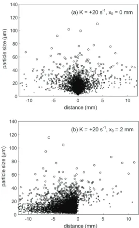
Figs. 3 and 4 show the film surface contamination in form of landing locations for randomly selected 5,000 fume particles on film surface for the cases of blowing air flow (K
= +20 s
-1) and suction air flow (K = -20 s
-1), respectively, both with and without applying air flow misalignment. Note that the landing locations of fume particles are sorted and arranged into particle diameter in these figures, so we can appreciate the particle dispersion characteristics with respect to fume particle size. The size of circular symbols in those figures is proportional to diameter of corresponding fume particles.
For cases of no air flow misalignment in Figs. 3(a) and
4(a), we find symmetric dispersion of fume particles along
Assessment of Air Flow Misalignment Effects on Fume Particle Removal in Optical Plastic Film Cutting Process 55
Fig. 4. Fume particle dispersion on optical plastic film surface for randomly sampled 5,000 particles for suction flow cases of K = -20 s
-1: (a) x
0= 0 mm and (c) x
0= 2 mm.
laser cut line (distance of 0 mm). It also shows that suction air flow motion (showing particles of almost all sizes stay near laser cut line on film) is much more advantageous for alleviating surface contamination to blowing air flow motion (fume particles especially 20 to 50 µm size range scatter far from the laser cut line).
If there exists air flow misalignment, its effect is somewhat different in two types of air flow motion. In Fig.
3(b), small fume particles (diameter from 10 to 20 µm) disperse much farther from laser cut line when air flow misalignment is applied for blowing air flow case and film surface contamination increases significantly. In case of suction air motions with air flow misalignment, most particles fell inside the film region between laser cut line and air flow misalignment line (x
0= 2 mm), regardless of their sizes, unless fume particles have not been vertically
Fig. 5. Particle size distributions of fume particles dispersed out of target margin for the cases of (a) K = +20 s
-1and (b) K = -20 s
-1showing the effects of flow misalignment. Symbols are from particle size measurements [12].
sucked out by rising suction air motion. Note that fume particle suction fraction is approximately 58.5 percent counted out of all 100,000 randomly sampled particles.
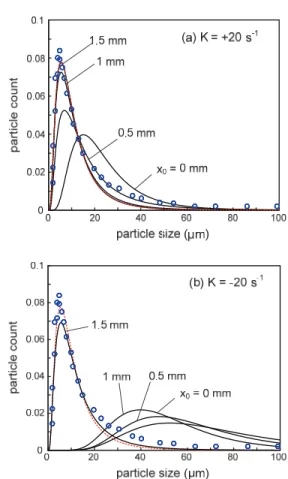
As a means to evaluate fume particle contamination on processed optical film, target margin is designated here to be of ±1.5 mm from laser cut line. Fume particles larger than a certain size (usually over 20 µm diameter) dispersed and landed outside this allowable target margin could become a source of film degradation by potentially blocking pixels in optoelectronics display units [7]. In Fig. 5, two types of air flow motion (blowing and suction) are shown and red dotted lines in each figure represent probabilistic lognormal distribution of particle sizes for ejecting fume particles from laser cut line.
Here in Fig. 5, the effects of air flow misalignment (x
0= 0,
Kyoungjin Kim · Joong-Youn Park 56
Fig. 6. Effects of air flow strength on fume particles dispersion out of target margin: (a) dispersion percentage and (b) mean diameter.
0.5, 1, and 1.5 mm) are tested to examine the particles size distributions of fume particles landed outside target margin.
If no air flow misalignment exists, fume particles landed outside target margin of ±1.5 mm is comprised of approximately 20 µm for blowing air motion and 40 µm diameter for suction air motion in average size. In case of blowing air motion, even small increase of air flow misalignment leads particle size distribution of dispersed fume particles quickly become closer to original particle sampling distribution, as shown in Fig. 5(a).
When air flow is suction motion as in Fig. 5(b), the change of particle size distribution of dispersed fume particles is much more gradual if the increase in air flow misalignment is below target margin. However, once air
flow misalignment matches or becomes larger than target margin, the particle size distribution of dispersed fume particles become quite close to original particle sampling distribution and it implies that fume particles of all sizes, not particular band of particle sizes, disperse and land outside the target margin of film cut.
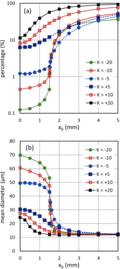
The dispersion fraction and average particle diameter of fume particles outside target margin out of randomly sampled 100,000 particles are evaluated in Fig. 6 in order to assess the effects of increasing air flow misalignment on film surface contamination for six values of air flow constant or strength K (from -20 to 20 s
-1). As discussed in Fig. 5, the effects are much more gradual in cases of blowing air motion (K = 5, 10, and 20 s
-1) and an increase of blowing air flow strength aggravates film surface contamination problem in general.
However, when suction air flow is applied, Fig. 6 shows that trends of particle dispersion fraction and mean diameter by an increase of air flow misalignment are different by giving much low values before reaching target margin and increasing sharply when misalignment goes over target margin. Therefore, fume particle suction should be applied by carefully positioning suction air flow alignment within target margin.
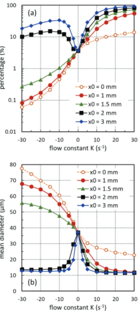
Fig. 8 now shows the effects of air flow constant K varying widely from -30 to +30 s
-1for five different values of air flow misalignment. The results can be conveniently compared to case of no air flow motion (K = 0), the point all the lines in the figures converge, and case of perfect air flow alignment (x
0= 0 mm, dotted line with open circular symbols).
On the side of positive K (blowing air flow motion), the effects of air flow misalignment are quite predictable as discussed before. In contrast, the cases of suction air flow motion with negative values of K show much complicated trends with varying degree of air flow misalignment. If x
0is within target margin of ±1.5 mm, the increase of film surface contamination is relatively limited with increasing suction flow strength.
However, if air flow misalignment x
0is larger than
designated target margin, film surface contamination
becomes as severe as the cases of blowing air motion. The
decrease of dispersion fraction for K over -10 s
-1for x
0= 2
and 3 mm is because of increased upward particle suction
by higher strength of suction air flow. Fig. 8 shows that
Assessment of Air Flow Misalignment Effects on Fume Particle Removal in Optical Plastic Film Cutting Process 57
Fig. 7. Effects of flow misalignment on fume particles dispersion out of target margin: (a) dispersion percentage and (b) mean diameter.
Fig. 8. Effects of flow misalignment on fume particles sucked out of film surface.
upward particle suction fraction strongly depends on suction air flow strength, but it is not affected by air flow misalignment.
4. Conclusions
This random particle simulation aims to investigate fume particle dispersion from laser cut line in precision processing of thin optical plastic film for optoelectronics display manufacturing. It uses probabilistic distribution for fume particle generation from laser cut line and particle trajectory calculations in blowing and suction air flow motions. The computational results are processed for assessing film surface contamination by particle dispersion and landing onto optical film in case there exists air flow misalignment from laser cut line. The major findings of this study show that film surface contamination outside target margin become significant if there is mismatch between air flow and laser cut line. This effect becomes critical in case of suction air motions applied to laser cutting.
Acknowledgement
This paper was supported by Research Fund from Kumoh National Institute of Technology.
References
1. MacDonald, W. A., “Engineered Films for Display Technologies,” Journal of Materials Chemistry, Vol. 14, pp. 4-10, 2004.
2. Ohshima, H., “Mobile Display Technologies: Past Developments, Present Technologies, and Future Opportunities,” Japanese Journal of Applied Physics, Vol. 53, pp. 03CA01-1-9, 2014.
3. Ni, H.-J., Liu, J.-G., Wang, Z.-H., and Yang, S.-Y., “A Review on Colorless and Optically Transparent Polyimide Films Chemistry, Process and Engineering Applications,” Journal of Industrial and Engineering Chemistry, Vol. 28, pp. 16-27, 2015.
4. Dubey, A. K. and Yadava, V., “Laser Beam Machining,”
International Journal of Machine Tools and Manufacture, Vol. 48, pp. 609-628, 2008.
5. Cho, K. W. and Park, H. J., “Laser Processing Technology in Semiconductor and Display Industry,”
Journal of the Korean Society for Precision Engineering, Vol. 27, pp. 32-38, 2010.
6. Powell, J., CO
2Laser Cutting, 2nd Ed., Springer-Verlag:
London, 1998.
Kyoungjin Kim · Joong-Youn Park 58