반도체디스플레이기술학회지 제19권 제2호(2020년 6월) Journal of the Semiconductor & Display Technology, Vol. 19, No. 2. June 2020.
Downward and Upward Air Flow Effects on Fume Particle Dispersion in Laser Line Cutting of Optical Plastic Films
Kyoungjin Kim
*†*†
Department of Mechanical System Engineering, Kumoh National Institute of Technology
ABSTRACT
In improving laser cutting of optical plastic films for mass production of optoelectronics display units, it is important to understand particle contamination over optical film surface due to fume particle generation and dispersion. This numerical study investigates the effects of downward and upward air flow motions on fume particle dispersion around laser cut line. The simulations employ random particle sampling of up to one million fume particles by probabilistic distributions of particle size, ejection velocity and angle, and fume particle dispersion and surface landing are predicted using Basset-Boussinesq-Oseen model of low Reynolds number flows. The numerical results show that downward air flow scatters fume particles of a certain size range farther away from laser cut line and aggravate surface contamination. However, upward air flow pushes fume particles of this size range back toward laser cut line or sucks them up with rising air motion, thus significantly alleviating surface contamination.
Key Words : Optical Plastic Film, Laser Cutting, Fume Particles, Stagnation Air Flow, Numerical Simulation
1. Introduction
1In optoelectronics display unit fabrication, various optical plastic thin films of novel properties are used in manu- facturing of most optoelectronics devices including thin-film transistor-driven active matrix liquid crystal display devices and active matrix organic light-emitting display devices as well as flexible mobile displays [1,2]. These optical plastic thin films are made of many different polymeric materials (PET, PC, PMMA, PEN, PAR, PES, PEEK, PI, etc.), and they possess required physical film qualities such as optical clarity, thermal stability, chemical resistance, dielectric fea- ture, and mechanical strength against scratching and bending [3].
Hence, it is important to develop and achieve an efficient line cutting process of large sized optical plastic film sheets into pre-determined sizes in mass production of optoelec- tronics displays. The precision cutting of thin plastic films
†
E-mail: [email protected]
usually employs CO
2laser system on highly automated large film sheet transport and positioning tables, as CO
2laser processing is known to provide high speed and high precision plastic film cutting with several advantages of narrow kerf width, smooth and flat cut finish, and relatively small plastic deformation [4,5].
As high-powered laser beam interacts with thin plastic
films in high-speed line cutting process, film cuts experience
melt shearing, burning and vaporization, and chemical
degradation of plastic material and thus laser cutting
generates undesirable fumes in the form of gas and soot
residues [6]. Aside from the fact that fumes are a source of
serious health risk, the soot particles, molten droplets, and
debris generated from high-speed laser cutting could land
and adhere onto the workpiece film surface. If film cut
suffers this particle contamination to a high degree, it may
degrade the processed optical films not usable in opto-
electronics display unit manufacturing. Since film surface
contamination by fume particles in laser cutting significantly
increases with higher cutting speed, this problem should be
Kyoungjin Kim 38
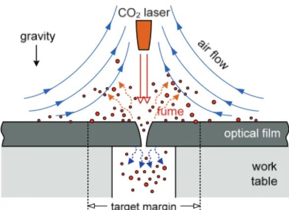
Fig. 1. Stagnation air flow over optical plastic film with fume particle generation in laser cut process.
resolved to improve film cutting quality and productivity simultaneously.
Therefore, it is necessary to understand fume particle dispersion phenomena in laser cutting process of optical plastic films. A previous research effort [7] introduced theoretical model for simulating fume particle dispersion behaviors from laser cut onto film surface in quiescent air environment. However, the most laser cutting processes generally use auxiliary ventilation or particle suction system in order to remove fume particles [8]. Thus, the effects of air flow should be taken into account in fume particle dis- persion model and simulations. This study now includes upward and downward air motions to numerically simulate and investigate how such air flow patterns affect fume particle dispersion and film surface contamination in a laser film cut process.
2. Particle Dispersion Model with Air Flow
Fig. 1 depicts fume particles generated from laser film cutting process of optical plastic films, and being ejecting and dispersing both into directions up and down. However, fume particles ejected upward are a matter of concern in this study of film surface contamination, once they land and stick on film surface. This study assumes that fume particles of all sizes are spherical, although their shapes could vary in actual CO
2laser plastic film cutting process.
Previous study [7] presumed that the surrounding air is quiescent, but this study introduces the stagnation air motion of upward (as shown in Fig. 1) and downward flow on film surface. Transient trajectory for fume particles of spherical
diameter d
pin a known air flow pattern can be described as the following form of Basset-Boussinesq-Oseen model [9].
(1)
(2)
where r(t) and v(t) are transient location and velocity vectors of each fume particle in a two-dimensional plane over the film surface across laser cut line, respectively. The vector g represents gravitation. In above equations, ρ
sand ρ
fare the mass densities of fume particle and surrounding air, respectively, and μ
fis dynamic viscosity of air. In Eq. (2), last term can be excluded due negligible unsteady effect on surrounding air by fume particle movement.
The flow velocity vector of air motion is shown as u and its components in horizontal and upward vertical directions from laser cut line are u
x= Kx and u
y= -Ky for an inviscid stagnation point flow. Here, the stagnation flow constant K describes the flow intensity and air flows faster with increasing value of this constant.
Note that positive value of K implies downward flow onto film surface, while negative value of K is for upward air flow motion away from the film surface. The reference point of x = 0 and y = 0 coincides with the laser cut line on film surface and so air flow pattern is symmetric along the laser cut line.
The drag coefficient C
don a small spherical particle moving in a fluid is usually given as semi-empirical functions of Reynolds number (Re
d= ρ
f|v-u| d
p/ μ
f). For a low Reynolds number flow regime up to Re
d< 1,000, the following equation is suitable for evaluating viscous drag on the fume particles from laser film cutting [10].
(3)
For the environment of stagnation point air flows moving downward or upward, transient fume particle trajectories of a given particle size can now be simulated by solving Eqs.
(1) and (2) simultaneously with particle drag model of Eq.
(3). However, it is difficult to know the initial ejection velocity and angle from laser cut line for fume particles of
r v dt d
t f f p f s p
f d p f
s p
t d d d d
d
d C dt d d
) ( 2
) 3 6 (
) 8 (
2 ) 6 (
2 3
2 3
u g v
u v u v v
) Re 158 . 0 1 Re (
24
2/3d d
C
d
Downward and Upward Air Flow Effects on Fume Particle Dispersion in Laser Line Cutting of Optical Plastic Films 39
Fig. 2. Probability distributions of random particle ejection velocity (a) and ejection angle (b) assumed for fume particles in laser film cutting process.
various sizes as well as the size distribution of fume particles. Such information is so far not well investigated or even understood.
Therefore, similarly as in previous study [7], this follow- up study also takes advantage of random nature in fume particle generation in laser cutting process. It will assume the probability distributions of particle ejection velocity in terms of lognormal distribution with mean of 1 m/s and standard deviation of 1 m/s. For particle ejection angles, we use normal distribution with mean of 0 degree (implying upward vertical direction) and standard deviation of 25 degrees. Fig. 2 shows those probability distributions. These assumptions are based on several experimental tests and observation of laser materials processing [11,12].
3. Results and Discussion
The present numerical model and investigations examine and discuss dispersion of fume particle from laser cutting in downward and upward air flows and subsequent particle contamination onto the optical film surface. Previous study [7] and industry observations confirmed that film surface contamination was mostly by fume particles whose size is approximately 30 µm. Thus, the effects of air flow motions are first investigated for the fume particles of this diameter.
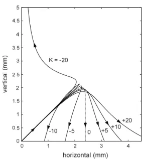
Fig. 3. Effect of downward (positive K) and upward (negative K) air flows on trajectories of 30 μm fume particles. Particle ejection velocity and angle are 1 m/s and 45 degrees.
Fig. 3 shows transient trajectories of 30 µm diameter fume particle whose ejection velocity and angle are 1 m/s and 45 degrees for seven different stagnation point flow constant K from -20 to 20 s
-1. The case of K = 0 (no air flow) gives a typical vertical drop of particle onto the surface after reaching maximum height in quiescent air. In case of downward flow or air blowing toward film surface (positive K), air flow pushes fume particles away and particle landing locations also move farther away. In contrast, if air flow is in upward motion (negative K), air flow moves fume particles toward the cutting line. Once upward air flow is strong enough (K = -20 s
-1), fume particles can be sucked away with rising air flow.
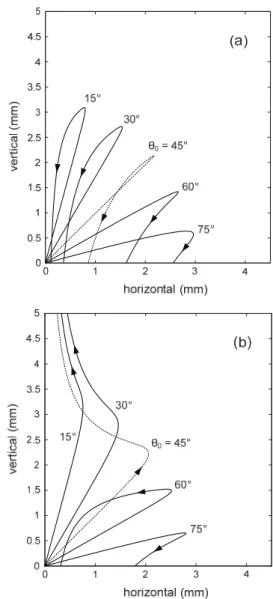
The effects of particle ejection angles from 15 to 75
degrees are shown on 30 µm fume particle trajectories for
downward air flow cases (K = +10 and +20 s
-1) in Fig. 4 and
upward air flow cases in (K = -10 and -20 s
-1) in Fig. 5. Both
figures indicate that particle ejection angle could play sig-
nificant role in determining fume particle landing location
on film surface and whether a particle is sucked out with air
flow in case of upward air motion. It is now evident that
upward air flow is more useful in alleviating fume particle
dispersion from laser cut line, while downward air flow
aggravates film contamination problem by dispersing fume
Kyoungjin Kim 40
Fig. 4. Effect of downward air flows on trajectories of 30 μm fume particles with ejection velocity of 1 m/s.
Ejection angle varies from 15 to 75 degrees: (a) K = +10, (b) K = +20 s
-1.
particles farther away from laser cut line than quiescent air.
At this time, 3,000 fume particles of 30 µm diameter are randomly sampled for particle ejection velocity and ejection angle from the probabilistic distributions shown in Fig. 2.
For three air flow cases of K = 0, +10, and -10 s
-1, each set of these 3,000 fume particles is tested and Fig. 6 shows those fume particle dispersion simulation results. The circles represent the landing locations of fume particles on optical film surface. The vertical coordinate at horizontal center of x
= 0 is laser cut line.
The cases of downward and upward air motions in Figs.
6(b) and 6(c), respectively, can be compared to the case of no air flow shown in Fig. 6(a) to appreciate how the air flow direction affects fume particle contamination on optical film surface. Here again, the downward air flow disperses fume particles farther from laser cut line than no air flow case.
Upward air flow motion narrows the dispersed area width of fume particles and it could significantly alleviate the film surface contamination.
Fig. 5. Effect of upward air flows on trajectories of 30 μm fume particles with ejection velocity of 1 m/s. Ejection angle varies from 15 to 75 degrees: (a) K = -10, (b) K
= -20 s
-1.
In order to quantify fume particle contamination, we use
allowable target margin from laser cut line and it is illu-
strated in Fig. 1. Previous study [7] discussed it in details for
no air flow cases. In laser cutting of optical films for mobile
display units, significant film surface contamination by
fume particles over this target margin degrades workpiece
film quality, because, for example, fume particles could
block the pixels. The target margin of ±1.5 mm is assigned
here, although its width could vary for many reasons.
Downward and Upward Air Flow Effects on Fume Particle Dispersion in Laser Line Cutting of Optical Plastic Films 41
Fig. 6. Particle dispersion on optical plastic film surface around laser cutting line for the simulation of 3,000 particles with randomly sampled ejection velocity and angle for 30 μm fume particle. Three levels of stagnation flow constant are tested for the cases of (a) K = 0, (b) K = +10, and (c) K = -10 s
-1.
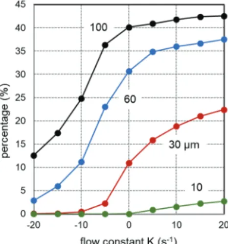
Fig. 7. Effects of stagnation flow constant and particle size on number fraction of fume particles dispersed out of target margin (±1.5 mm).
Fig. 7 shows the number fraction of fume particles dis- persed outside target margin from laser cut line. It is evalu- ated from the random simulation results of 100,000 particles (with same approach as the cases shown in Fig. 6.) for
different particle diameters from 10 to 100 µm. It is apparent that larger fume particles are more likely to disperse outside target margin than small ones. Also, we find that larger fume particles are more significantly affected by upward air flow than by downward air flow.
So far, dispersion simulations of random particles over film surface have assumed constant particle size. However, actual laser cutting of optical plastic film may generate fume particles of all different sizes. Hence, we now employ the random sampling of particle diameter in addition to particle ejection velocity and ejection angle from cutting line. Here, probabilistic distribution of particle diameter for random sampling follows lognormal distribution. The mean of 12 µm and variance of 100 µm
2are given for this probability function. They are based on lognormal fitting to particle measurements on laser processing fumes [11].
As the simulation results of such random particle sam- plings, Fig. 8 shows the film landing locations of 10,000 fume particles on film surface for the cases of no air flow (K
= 0), downward flow (K = +10 s
-1), and upward flow (K = -
10 s
-1). The fume particles are sorted into particle diameter
Kyoungjin Kim 42
Fig. 8. Fume particle dispersion on optical plastic film surface for randomly sampled 10,000 particles for three stagnation air flow cases of (a) K = 0, (b) K = +10, and (c) K = -10.
in these figures. Thus, we can examine the dispersion characteristics depending on fume particle size for a given air flow condition. The size of circles in Fig. 8 is propor- tional to diameter of corresponding fume particles.
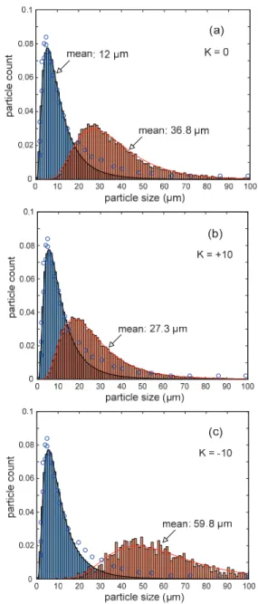
Fig. 9. Particle size distributions of original fume particle generation (left) and particles dispersed out of target margin (+1.5 mm, right) for three stagnation air flow cases of (a) K = 0, (b) K = +10, and (c) K = -10 s
-1.
We observe generally that majority of small fume
particles (under 10 µm) stay very near the laser cut line, and
larger fume particles tend to disperse and land far away
from laser cut line. When compared to no air flow case in
Fig. 8(a), here again, Figs. 8(b) and 8(c) demonstrates the
effects of downward air flow for aggravating and upward air
Downward and Upward Air Flow Effects on Fume Particle Dispersion in Laser Line Cutting of Optical Plastic Films 43
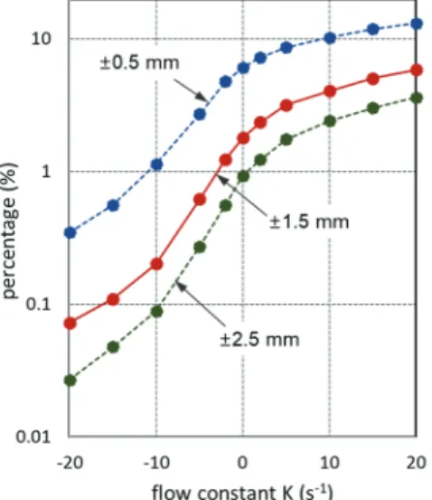
Fig. 10. Effects of stagnation flow constant on number fraction of fume particles dispersed out of target margin (±0.5, ±1.5, ±2.5 mm).
flow for alleviating particle contamination problem, respec- tively, in terms of fume particle dispersion width on film surface in laser cut process.
In examining Fig. 8, it is difficult to well understand how a specific range of particle size from random size sampling reacts to each air flow motion case. Hence, Fig. 9 shows particle size distribution only for fume particles dispersed and landed outside target margin of ±1.5 mm (right curves in orange color), so it can be compared to original fume particle size distribution from laser cut (left curves in blue color). Each air flow motion case in this figure involves one million fume particles from random sampling for particle size, particle ejection velocity and ejection angle.
In case of no air motion (K = 0), mean particle size outside target margin is 36.8 µm, as shown in Fig. 9(a). If a statistically identical set of fume particles is under influence of downward air flow (K = +10 s
-1in Fig. 9(b)), mean particle size outside target margin is now 27.3 µm and its particle size distribution also shifts toward smaller size. It is because that downward air motion pushes away much more portion of fume particles with 10-30 µm size range than the case of no air motion. In contrast, if upward air flow (K = - 10 s
-1in Fig. 9(c)) is applied, mean particle size outside target margin is almost 60 µm, but its particle size distri- bution shifts toward larger size. At this time, upward air motion effectively removes much portion of fume particles
with 10-30 µm size range by either sucking out those par- ticles or pushes them back inside target margin.
The effects of stagnation flow constant on number frac- tions of fume particles landed outside target margin are summarized in Fig. 9 for three width of target margin. It is evaluated by random sampling of 100,000 fume particles and trajectory simulation with same approach. It shows once again upward and downward air flow motions over laser cutting can favorably or adversely affect fume particle contamination on optical plastic film surface.
4. Conclusions
This numerical investigation on laser film cutting process in optoelectronics display manufacturing focuses on fume particle dispersion over optical plastic film surface under the influence of downward and upward stagnation air flow motions. The random particle simulations of ejected fume particles from laser cut line were carried out by using probabilistic distribution of particle size as well as ejection velocity and angle. The numerical results show that down- ward air flow disperses and pushes away fume particles of 10-30 µm size farther outside allowable target margin of laser line cutting. On the contrary, upward air flow may alleviate particle contamination by sucking out fume particles of same range or pushing them back toward laser cut line.
Acknowledgements
This paper was supported by Research Fund from Kumoh National Institute of Technology.
References
1. MacDonald, W. A., “Engineered Films for Display Technologies,” Journal of Materials Chemistry, Vol. 14, pp. 4-10, 2004.
2. Ohshima, H., “Mobile Display Technologies: Past Developments, Present Technologies, and Future Opportunities,” Japanese Journal of Applied Physics, Vol. 53, pp. 03CA01-1-9, 2014.
3. Ni, H.-J., Liu, J.-G., Wang, Z.-H., and Yang, S.-Y., “A
Review on Colorless and Optically Transparent
Polyimide Films Chemistry, Process and Engineering
Applications,” Journal of Industrial and Engineering
Chemistry, Vol. 28, pp. 16-27, 2015.
Kyoungjin Kim 44