학 술 논 문
285
온도 조절형 고주파 시스템 및 식염수 분사를 고려한 전극도자절제술용 전극의 수치 모델 개발
안진우
1,2·김영진
1·이승아
1·정하철
1·김경아
2·차은종
2·문진희
11오송첨단의료산업진흥재단 첨단의료기기개발지원센터, 2충북대학교 의과대학 의공학교실
Development of Numerical Model of Electrode for Radiofrequency Catheter Ablation Considering Saline Irrigation and
Temperature-controlled Radiofrequency System
Jin-Woo Ahn
1,2, Young-Jin Kim
1, Seung-A Lee
1, Ha-Chul Jung
1, Kyung-Ah Kim
2, Eun-Jong Cha
2and Jin-Hee Moon
11Medical Device Development Center, Osong Medical Innovation Foundation, Republic of Korea,
2Dept. of Biomedical Engineering, School of Medicine, Chungbuk National University (Manuscript received 22 September 2017 ; revised 9 November 2017 ; accepted 19 November 2017)
Abstract: Radiofrequency catheter ablation is the interventional therapy that be employed to eliminate cardiac tissue caused by arrhythmias. During radiofrequency catheter ablation, The thrombus can occur at electrode tip if the tem- perature of tissue and electrode is excess 100oC. To prevent this phenomenon, we investigated numerical model of electrode for radiofrequency catheter ablation considering saline irrigation and temperature-controlled radiofrequency system. The numerical model is based on coupled electric-thermal-flow problem and solved by COMSOL Mult- iphysics software. The results of the models show that the dimensions of the thermal lesion are increased if the flow rate of the saline irrigation and the set temperature are increased. The surface width characterized to determine the thermal lesion isn’t need to measure in temperature-controlled radiofrequency system due to convective heat trans- fer by saline irrigation at tissue-electrode interface.
Key words: Radiofrequency catheter ablation, Numerical analysis, Arrhythmia, Electrode of catheter, Saline irrigation, Thrombus
I. 서 론
전극도자절제술(radiofrequency catheter ablation)은 부정맥(arrhythmia)을 치료하는 중재 시술 중 한 방법이다.
이 시술은 정맥을 통해 절제술용 카테터(ablation catheter) 를 심장 내 진입시킨 후, 절제술용 카테터의 전극과 환자의
등에 부착된 접지 전극 사이에 고주파 전류(radiofrequency current)를 인가하여 열을 발생시킴으로 이루어진다. 전극 에서 발생한 열은 부정맥을 일으키는 심장 조직을 괴사 시 켜 부정맥을 치료 할 수 있다. 전극도자절제술이 수행되는 동안 심장 조직과 전극의 온도가 100oC 이상으로 상승하면, 심장 내 흐르는 혈류가 전극에 접착되어 혈전(thrombus)이 생기게 되며, 이는 심장 조직의 임피던스를 증가시켜 전극 에서 미세폭발(microexplosion)을 일으키는 원인으로 작용 한다[1-3]. 이러한 현상을 방지하기 위하여 온도 조절형 고 주파 시스템(temperature-controlled radiofrequency sys- tem)이 개발 되었다[1,3]. 전극 내에 온도 센서가 구비되어 설정된 온도에 따라 고주파 발생기에 피드백하여 파워를 제 Corresponding Author : Jin-Hee, Moon
123 Osongsaengmyeong-ro Osong-eup, Heungdeok-gu, Cheongju- si, Chungcheongbuk-do 28160, Korea
TEL: +8243-200-9753 / E-mail: [email protected] 본 연구는 산업통산자원부 산업기술혁신사업(No.10049761)과 과학 기술정보통신부의 재원으로 한국연구재단의 지원을 받아 수행된 기 초연구사업임(No. NRF-2015R1C1A1A02037795).
286
어한다. 또한, 식염수 분사를 위한 홀이 구비된 전극이 개발 되어 이를 통하여 식염수(saline)을 분사(injection) 함으로 써 전극에 혈전이 발생하는 것을 방지한다[4-9].
심장 내 전극도자절제술에 의해 괴사된 조직의 병변을 예 측하고 실험을 수를 줄이고자 전극도자절제술에 대한 수치 해석이 연구되었다[3,10-17]. 온도 조절형 고주파 시스템은 전극 끝단(tip)의 온도에 따라 고주파 발생기의 파워를 제어 하므로, 수치해석 시 전극 끝단의 온도에 영향을 주는 심장 내 혈류, 심장 조직간 열전달, 식염수 분사로 인한 전극의 열전달을 모두 고려해야 한다. 하지만, 기존 연구들은 심장 내 혈류 또는 식염수 분사에 대한 열유동을 수치해석에 포 함 않은 한계점이 있다. 심장 내 혈류에 대한 영역을 무시하 고 대류 열전달 계수(convective heat transfer coefficient) 를 이용한 열 유속(heat flux) 경계 조건으로 대체하거나, 심장 내 혈류에 대한 영역을 고려한 연구조차도 열 유속 경 계조건으로 대체하여 해석을 수행하였다[3,11,14-16]. 또한, 식염수 분사로 인해 변화하는 유동이 전극, 혈류, 심근 조직 에 대류 열전달에 영향을 미치므로 식염수 분사 유동을 고 려해야 하지만, 이를 무시하거나 전극 끝단에 일정한 온도 로 경계조건을 대체하여 수치해석을 수행하였다[11]. 일부 연구는 전극의 식염수 분사에 대한 유동을 고려하여 해석했 으나, 식염수가 전극의 분사 홀을 통해 분사되는 현상을 전 극 표면에서 식염수가 분사 하는 조건으로 단순화 하였다.
이에 전극의 온도를 결정하는 전극 내 식염수 분사에 의한 열전달 현상이 정확하게 고려되지 않았다[10,13].
본 연구는 온도 조절형 고주파 시스템에서 파워를 제어하 는 요소인 전극 팁의 온도에 영향이 미치는 심장 내 혈류 및 식염수 분사 유동을 수치해석 방법으로 모델링하여, 식 염수 분사 유량과 전극 끝단의 온도에 따른 조직 괴사 병변 의 변화를 예측하고자 한다.
II. 연구 방법
1. 문제 정의 및 모델 구성
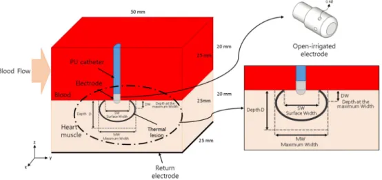
수치해석 하고자 하는 모델은 그림 1에 도시하였다. 모델 은 심장 내 혈류 영역(blood), 심장 조직(heart tissue), 카 테터 전극(electrode)으로 구성된다. 구성 요소를 표현하기 위해 그림 1은 YZ 평면의 대칭으로 절반 부분을 제거하여 도시한 것이며, 해석 시에는 대칭하지 않고 완전한 영역으 로 해석을 수행 하였다. 심장 조직과 심장 내 혈류 영역에 대한 너비, 길이, 높이는 50, 50, 20 mm 이며, 카테터의 직 경은 7.5 mm이다[5,10,16]. 식염수가 분사되는 전극의 홀 의 직경은 0.5 mm이며 전극에 6개가 구비된 것으로 모델 링하였다. 카테터 전극은 심장 조직과 접촉되어 1 mm 삽 입 되어있다.
2. 지배 방정식
심장 내 혈류 및 식염수 분사를 포함하는 유동과 전극에 인가되는 전압을 포함하는 열전달을 풀기 위해서는, 전기장, 속도장(유동), 온도(열)를 동시에 풀어야 한다. 이 때 전기장, 유동, 열 문제가 서로 연동(coupled)되어야 한다. 열전달 문 제에 관한 지배 방정식은 식 (1)과 같이 기술되는 Penne의 생체-열 방정식(bio-heat equation)이다[17]. 여기서 ρ는 밀 도(density, kg/m3), cp는 비열(specific heat, J/K/kg), k는 열 전도도(thermal conductivity, W/m/K), T는 온도(tem- perature, K), q는 고주파 전류에 의한 열 원(heat source caused by radiofrequency current, W/m3), Qp는 관류 (blood perfusion)에 의한 열손실(W/m3), Qm은 신진대사 열(metabolic heat, W/m3), u는 속도장(velocity field, m/
s)이다. 본 연구에서는 식 (1)과 같이 관류에 의한 열손실 (Qp)과 신진대사 열(Qm)은 영향이 미비하여 고려하지 않았
그림 1. 수치 모델에 대한 구성요소와 열 병변 치수 정의.
Fig. 1. Definition of elements of the model and characteristic dimension of the thermal lesion in numerical model.
287 다[18,19].
식 (1)
고주파 전류는 500 kHz 주파수 내외에서 인가하며, 이로 인한 변위 전류(displacement current)와 전도 전류(con- duction)를 고려해야 한다. 하지만 본 수치 모델에서 생물 학적 매질과 해석하고자 하는 영역의 크기에서는 변위 전류 가 전도 전류보다 낮기 때문에 전도 전류에 의해 발생하는 저항 열(resistive heat)만 고려할 수 있다[10,20,21]. 따라 서 전기장 문제는 준정적 접근(quasi-static approach)이 가능하게 되어 식 (2), (3)과 같이 기술된다. 이때, σ는 전기 전도도(electrical conductivity, S/m), E는 전기장(elec- tric field, V/m)으로, φ는 전기 포텐셜(electric potential, V)을 도입하여 계산한다. 에너지 방정식에서 고주파 전류에 의한 열 원(q)은 식 (4)와 같다.
식 (2)
식 (3)
식 (4)
심장 내 혈류와 식염수 분사 유동에 대한 지배 방정식은 비 압축성 나비에-스톡스 방정식이며(imcompressible Navier- Stokes equation)이며 식 (5)와 (6)과 같이 기술 된다. 이 때, ρ는 밀도(density, km/m3), P는 압력(pressure, Pa), μ 는 점도(viscosity, Pa·s) 이다.
식 (5)
식 (6)
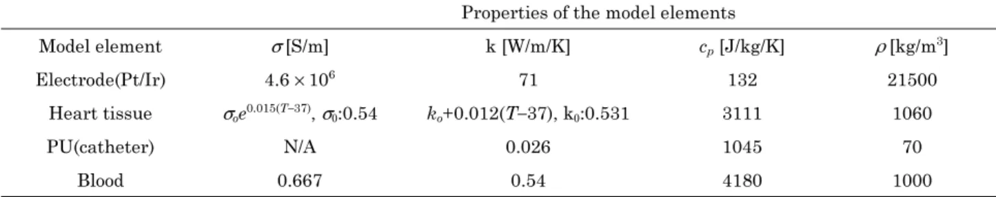
3. 재료 물성치 및 경계조건
모델 구성 요소에 대한 전기, 열, 유동 관련 물성치 표 1
과 같다[10,16]. 심장 조직에 대한 전기적 및 열 전도도는 온도에 대한 함수로 정의하였다. 혈류에 대한 점도 및 밀도 는 0.0021 Pa·s, 1000 kg/m3이고[10,16], 식염수의 점도 및 밀도는 물의 물성치를 사용하여 각각 0.001 Pa·s, 1000 kg/
m3로 설정하였다.
수치 모델에 대한 전기, 열, 유동 관련 경계 조건을 그림 2와 같다. 본 수치 모델은 PI(Proportional-integral) 제어 알고리즘을 적용하여 온도 조절형 고주파 시스템을 구현하 였다[3]. 온도를 측정하는 지점 은 전극과 심장 조직의 계 면에 있으며 설정 온도(Tset)를 설정하고 계측하는 점에서의 온도가 설정 온도(Tset)보다 높게 되면 식 (7)과 같이 피드 백 전압(Vctrl)이 계산되며 전기장의 전기 포텐셜(φ)에 식 (8) 과 같이 반영이 된다. PI 알고리즘의 비례기와 적분기 상수 (Kp, Ki)는 각각 7, 5로 설정하였다. 전극의 설정 온도(Tset) 는 5oC 단위로 35oC에서 50oC까지 설정하였다.
식 (7)
식 (8) ρcP∂T
--- ∇ k T∂t= ⋅( ∇ ) q Q+ – p+Qm–ρcu T⋅∇
∇ σE⋅( )=0
E=–∇φ
q 1 2---σE2
=
ρ∂u--- ρu ∇u ∇P μ∇∂t+ ⋅ =– + 2u
ρ∇ u⋅ =0 Vctrl( ) Kt p(Tprobe( ) Tt – set) Ki (Tprobe( ) Tτ – set) τd
0
∫t
+
=
φ t() V V= – ctrl( )t
표 1. 모델 요소의 물성치
Table 1. Material properties of elements of the model.
Properties of the model elements
Model element σ [S/m] k [W/m/K] cp [J/kg/K] ρ [kg/m3]
Electrode(Pt/Ir) 4.6× 10⁶ 71 132 21500
Heart tissue σoe0.015(T−37), σ0:0.54 ko+0.012(T−37), k0:0.531 3111 1060
PU(catheter) N/A 0.026 1045 70
Blood 0.667 0.54 4180 1000
그림 2. 모델의 전기, 유동, 열 관련 경계 조건.
Fig. 2. Electrical, fluid flow and thermal boundary con- ditions of the model.
288
유동 문제에서는 심장 내 혈류에 대한 유동을 Y 방향으 로 0.1 m/s로 설정하였다[4,8,10]. 그 반대 경계면은 출구 경 계면이며 대기압으로 설정 하였다. Z 방향 상단 경계면에는 열린 경계(open boundary)로 설정하였다. 일부 문헌에서는 상단 경계면에서 속도를 0인 no slip 조건으로 설정하였으 나, 이는 벽면 효과(wall effect)를 발생시켜 심장 내 혈류 에 영향을 미칠 것으로 판단된다. 식염수 분사에 대한 속도 조건은 식염수 분사 유량(Qf)으로 설정하여 5 ml/min 단위 로 5 ml/min에서 20 ml/min까지 설정하였다. 열 문제에서 는 각 바깥 경계면에서 온도는 37oC로 일정하게 설정하였 다. 초기 온도는 식염수만 20oC이고 그 외 다른 요소는 37oC 로 설정하였다.
모델의 해석은 COMSOL Multiphysics 5.2(COMSOL Inc.) 소프트웨어를 이용하여 PI 제어 알고리즘과 전기, 유 동, 열 문제를 해석하였다. 해석 시간은 30 s이고 시간 단계 (time step)은 최대 0.2 s로 설정 하였다.
III. 연구 결과
1. 열 병변(thermal lesion)에 대한 정의
심장 조직이 50oC 이상이면 비가역적으로 변하게 되며 열 로 괴사된 병변을 50oC 등온선으로 식별하고자 한다[3,10, 15,16,22]. 그리고 열 병변의 치수를 최대 깊이 D(maxi- mum depth), 최대 너비 MW(maximum width), 최대 너 비에서의 깊이 DW(depth at the maximum width), 표 면 너비 SW(surface width)f를 통해 평가하였으며 그림 1
에 도시하였다[4,8]. 이 4가지 치수는 열 병변의 부피를 구 하는 공식에 사용된다[4,23].
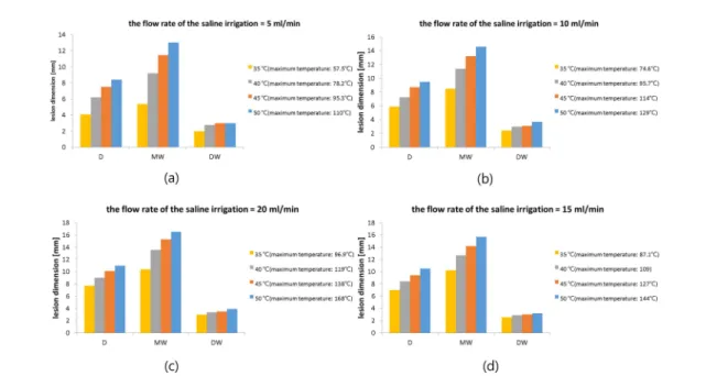
2. 식염수 분사 유량에 따른 결과
전극의 설정 온도(Tset)을 5oC 단위로 35oC에서 50oC까 지 및 식염수 분사 유량(Qf) 5 ml/min 단위로 5 ml/min에 서 20 ml/min까지 파라미터 해석을 수행하였고 각 조건에 서의 열 병변 치수를 그림 3과 같이 도시하였다. 전극의 설 정 온도(Tset)가 증가할수록 열 병변의 치수 최대 깊이(D), 최대 너비(MW), 최대 너비에서 깊이(DW)가 모두 증가하 는 것을 살펴 볼 수 있고, 최대 너비에서 깊이(DW)는 나머 지 두 치수에 비해 증가 폭이 작은 것을 보여준다. 그리고 전극의 설정 온도(Tset)가 같고 식염수 분사 유량(Qf)에 따 른 결과를 살펴 보기 위해 그림 4와 같이 해석된 결과에서 전극의 설정 온도(Tset)가 40oC에서 식염수 분사 유량(Qf)에 따른 전극 팁에서의 온도 및 전기 포텐셜을 도시하였다. 식 염수 분사 유량(Qf)로 인해 전극의 내부 온도가 초기에 감 소 및 오버슛(overshoot) 되는 것을 살펴 볼 수 있고, 식염 수 분사 유량(Qf)이 증가 할수록 감소되는 설정 온도(Tset) 에 따라 피드백 제어를 시작하는 시간이 늦어 지는 것을 알 수 있다. 이는 식염수 분사 유량의 온도는 20oC이므로 식 염수 분사 유량(Qf)이 증가 함에 따라 전극 내부에서 식염 수 분사에 의한 대류 열전달이 증가하여 전극의 팁 온도가 감소 되는 것에 기인한다. 그러므로 전극의 설정 온도(Tset) 가 일정하고 식염수 분사 유량(Qf)이 증가함에 따라 열 병 변의 치수 모두가 증가하는 것을 살펴 볼 수 있다.
그림 3. 설정 온도(Tset)에 따른 열 병변 수치 결과. (a) Qf= 5 ml/min, (b) Qf= 10 ml/min, (c) Qf= 15 ml/min, (d) Qf= 20 ml/min.
Fig. 3. Results of characteristic dimension of the thermal lesion according to setting temperature(Tset). (a) Qf= 5 ml/min, (b) Qf= 10 ml/min, (c) Qf= 15 ml/min, (d) Qf= 20 ml/min.
289 3. 표면 너비 관련
그림 5는 전극의 설정 온도(Tset)가 45oC, 50oC, 식염수 분사 유량(Qf)이 10 ml/min, 0 ml/min 인 경우의 온도 분 포 결과를 도시하였다. 그림 5(a) 및 (b)는 YZ 평면에서의 단면에서 살펴본 것으로, 앞서 정의한 열 병변의 치수 중에 하나인 표면 너비(SW)를 측정 할 수 있다. 반면 XY 평면 에서의 단면도인 그림 (c) 및 (d)는 식염수 분사에 의해서
열 병변이 여러 영역으로 나뉘거나 심장 내 혈류에 의해 표 면 너비(SW)를 측정 할 수 없다. 따라서 온도 조절형 고주 파 시스템에서는 열 병변 치수 중에 하나인 표면 너비(SW) 무의미 하며, 표면 너비(SW)를 이용한 열 병변의 부피를 계 산한 값도 마찬가지라 판단된다.
IV. 결 론
본 연구는 전극도자절제술에서 온도 조절형 고주파 시스 템을 이용하여 심장 내 혈류와 식염수 분사가 가능한 전극 을 전극의 식염수 분사 유량(Qf)와 설정 온도(Tset)에 따른 심장 조직의 병변 변화를 수치해석 방법으로 수행하였다. 식 염수 분사 유량(Qf)와 설정 온도(Tset)가 증가함에 따라 열 병변의 최대 깊이(D), 최대 너비(MW), 최대 너비에서의 깊 이(DW)도 증가하는 것을 확인 하였다. 그리고 열 병변의 표 면 너비(SW)는 심장 조직-전극-심장 내 혈류 계면에서 식 염수 분사 유동에 의한 대류 열전달로 인해 무의미함을 확 인 하였고, 이러한 열 병변의 수치를 이용한 열 병변의 부 피를 계산하는 것이 적절하지 않다고 판단된다. 본 모델에 서는 전극이 심장 조직에 대하여 서로 수직인 위치에서만 수치해석을 수행하였지만, 수평인 위치와 다른 위치에서 수 치해석을 수행하여 위치에 따른 열 병변을 살펴 볼 필요 가 있다고 판단된다.
그림 4. 설정 온도(Tset)가 40oC일 때, 전국 팁에서 식염수 분사 유량 (Qf)에 따른 온도 및 전기 포텐셜 결과.
Fig. 4. Results of temperature and electric potential in electrode tip according to flow rate of saline irrigation(Qf), when the setting temperature(Tset) is 40oC.
그림 5. YZ평면과 XY평면에 따른 단면에서의 온도 분포. (a) 및 (c) Qf= 10 ml/min, Tset= 45oC, YZ 평면의 단면, (b) 및 (d) Qf= 0 ml/
min, Tset = 50oC XY 평면의 단면.
Fig. 5. Distribution of temperature in cross section according to YZ and XY plane. (a) and (c) Qf= 10 ml/min, Tset= 45oC, cross section of YZ plane, (b) and (d) Qf= 0 ml/min, Tset= 50oC cross section of XY plane.
290
참고문헌
[1] McRury, I.D., and Haines, D.E., “Ablation for the treatment of arrhythmias,” Proceedings of the IEEE, vol. 84, no. 3, pp.
404-416, 1996.
[2] Haines, D.E. “The biophysics of radiofrequency catheter ablation in the heart: the importance of temperature monitor- ing,” Pacing and Clinical Electrophysiology, vol. 16, no. 3, pp. 586-591, 1993.
[3] Jain, M.K. and Patrick D.W. “Temperature-controlled and constant-power radio-frequency ablation: what affects lesion growth?,” IEEE Transactions on Biomedical Engineering, vol. 46, no. 12, pp. 1405-1412, 1999.
[4] GUERRA, J.M., JORGE, E., RAGA, S., G LVEZ-MONT N, C., ALONSO-MART N, C., RODR GUEZ-FONT, E., CINCA, J., and VI OLAS, X. “Effects of Open-Irrigated Radiofre- quency Ablation Catheter Design on Lesion Formation and Complications: In Vitro Comparison of 6 Different Devices,”
Journal of cardiovascular electrophysiology, vol. 24, no. 10, pp. 1157-1162, 2004.
[5] WOOD, M.A., GOLDBERG, S.M., PARVEZ, B., PATHAK, V., HOLLAND, K., ELLENBOGEN, A.L., HAN, F.T., ALEXANDER, D., LAU, M., RESHKO, L. and GOEL, A.
“Effect of electrode orientation on lesion sizes produced by irrigated radiofrequency ablation catheters,” Journal of car- diovascular electrophysiology, vol. 20 no. 11, pp. 1262-1268, 2009.
[6] EVERETT IV, T.H., LEE, K.W., WILSON, E.E., GUERRA, J.M., VAROSY, P.D., and OLGIN, J.E. “Safety profiles and lesion size of different radiofrequency ablation technologies:
a comparison of large tip, open and closed irrigation cathe- ters,” Journal of cardiovascular electrophysiology, vol. 20, no. 3, pp. 325-335, 2009.
[7] Demazumder, D., Mirotznik, M.S., and Schwartzman, D.
“Biophysics of radiofrequency ablation using an irrigated electrode,” Journal of interventional cardiac electrophysiol- ogy, vol. 5, no. 4. pp. 377-389, 2001.
[8] Yokoyama, K., Nakagawa, H., Wittkampf, F.H., Pitha, J.V., Lazzara, R., and Jackman, W.M. “Comparison of electrode cooling between internal and open irrigation in radiofre- quency ablation lesion depth and incidence of thrombus and steam pop,” Circulation, vol. 113, no. 1, pp. 11-19, 2006.
[9] Weiss, C., Antz, M., Eick, O., Eshagzaiy, K., Meinertz, T., and Willems, S. “Radiofrequency catheter ablation using cooled electrodes: impact of irrigation flow rate and catheter contact pressure on lesion dimensions,” Pacing and Clinical Electrophysiology, vol. 25, no. 4, pp. 463-469, 2002.
[10] González-Suárez, A., Berjano, E., Guerra, J.M., and Gerardo- Giorda, L. “Computational modeling of open-irrigated elec- trodes for radiofrequency cardiac ablation including blood motion-saline flow interaction,” PloS one, vol. 11, no. 3, pp.
e0150356, 2016.
[11] Pérez, J.J., D'avila, A., Aryana, A., and Berjano, E. “Electri- cal and thermal effects of esophageal temperature probes on radiofrequency catheter ablation of atrial fibrillation: results
from a computational modeling study,” Journal of cardiovas- cular electrophysiology, vol. 26, no. 5, pp. 556-564, 2015.
[12] Jain, M.K. and Patrick D.W. “A three-dimensional finite ele- ment model of radiofrequency ablation with blood flow and its experimental validation,” Annals of biomedical engineer- ing, vol. 28, no. 9, pp. 1075-1084, 2000.
[13] Gopalakrishnan, J. “A mathematical model for irrigated epi- cardial radiofrequency ablation,” Annals of biomedical engi- neering, vol. 30, no.7, pp. 884-893, 2002.
[14] Gallagher, N., Fear, E.C., Byrd, I.A., and Vigmond, E.J.
“Contact geometry affects lesion formation in radio-frequency cardiac catheter ablation,” PloS one, vol. 8, no. 9, pp. e73242, 2013.
[15] Tungjitkusolmun, S., Woo, E.J., Cao, H., Tsai, J.Z., Vorpe- rian, V.R., and Webster, J.G. “Thermal-electrical finite ele- ment modelling for radio frequency cardiac ablation: effects of changes in myocardial properties,” Medical and Biologi- cal Engineering and Computing, vol. 38, no. 5, pp. 562-568, 2000.
[16] González-Suarez, A. and Berjano, E. “Comparative analysis of different methods of modeling the thermal effect of circu- lating blood flow during RF cardiac ablation,” IEEE Trans- actions on Biomedical Engineering, vol. 63, no. 2, pp. 250- 259, 2016.
[17] Pennes, H.H. “Analysis of tissue and arterial blood tempera- tures in the resting human forearm,” Journal of applied phys- iology, vol. 1, no. 2, pp. 93-122, 1948.
[18] Obradovi , M., Avilla, A., Thiagalingam, A., and Filipovi , N. “Finite element modeling of the endocardial radiofre- quency ablation,” J Serbian Soc Comput Mech, vol. 4, no. 2, pp. 43-53, 2010.
[19] Haines, D.E. and Denny D.W. “Tissue heating during radiof- requency catheter ablation: a thermodynamic model and observations in isolated perfused and superfused canine right ventricular free wall,” Pacing and Clinical Electrophysiol- ogy, vol. 12, no. 6, pp. 962-976, 1989.
[20] Doss, J.D. “Calculation of electric fields in conductive media,”
Medical physics, vol. 9, no. 4, pp. 566-573, 1982.
[21] Plonsey, R. and Heppner, D.B. “Considerations of quasi-sta- tionarity in electrophysiological systems,” Bulletin of mathe- matical Biology, vol. 29, no. 4, pp. 657-664, 1967.
[22] MORENO, J., QUINTANILLA, J.G., MOLINA-MOR A, R., GARC A-TORRENT, M.J., ANGULO-HERN NDEZ, M.J., CURIEL-LLAMAZARES, C., RAMIRO-BARGUE O, J., GONZ LEZ, P., CAAMA O, A.J., P REZ-CASTELL- ANO, N., ROJO- LVAREZ, J.L., MACAYA, C., and P REZ- VILLACAST N. “Morphological and Thermodynamic Com- parison of the Lesions Created by 4 Open-Irrigated Catheters in 2 Experimental Models,” Journal of cardiovascular elec- trophysiology, vol. 25, no. 12, pp. 1391-1399, 2014.
[23] Nguyen, D.T., Olson, M., Zheng, L., Barham, W., Moss, J.D., and Sauer, W.H. “Effect of irrigant characteristics on lesion formation after radiofrequency energy delivery using abla- tion catheters with actively cooled tips,” Journal of cardio- vascular electrophysiology, vol. 26, no. 7, pp. 792-798, 2015.
A′ O′
′I ′I
N˜
′c ′c
U′
′I A′
N˜
A′ N˜ E′
A′ E′
′I