Vol. 18, No. 8 pp. 25-33, 2017
Fabrication and Performance Evaluation of MR-16 Lamp Series with Narrow Angular Distribution of Luminous Intensity Using an
Aspherical Planar-convex 2×2 Fly-eye Lens Type
Kyung-duk Chu
1, Jae Myung Ryu
2, Chun-Gang Hong
3, Youn Hong Jeong
4, Jae Heung Jo
1*1Department of Photonics and Sensors, Hannam University
2Department of Optical Engineering, Kumoh National Institute of Technology
3KangDong Tech co. LTD
4Department of Optometry, Kookje University
평면-비구면 2×2 fly-eye 렌즈형태의 2차 렌즈를 사용한 고효율의 좁은 배광각을 갖는 MR-16 램프 시리즈 제작 및 성능평가
추경덕1, 류재명2, 홍춘강3, 정연홍4, 조재흥1*
1한남대학교 공과대학 광·센서공학과
2금오공과대학교 광시스템공학과
3㈜강동테크
4국제대학교 안경광학과
Abstract This paper reports the optical design of the MR-16 lamp series with a LED second lens and an aspherical plano-convex lens suitable for a simple and rapid injection molding fabrication method. The fabrication and performance evaluation of the MR-16 lamp series, which was designed with a narrow angular distribution of luminous intensity, were conducted to replace halogen lamps with LED lamps. Four types of LED lamps were fabricated, which have angular distributions of luminous intensity of 22.4°, 31.1°, 37.3°, and 59.9° and luminous efficiencies of 76.5 lm/W, 75.2 lm/W, 72.0 lm/W, and 77.8 lm/W, respectively, while their spreading angles with an illuminance uniformity of 81% were 3°, 15°, 22°, and 49°, respectively. After eliminating a yellow tail of the LED lamps using a diffusion sheet, the angular distributions of the luminous intensity were measured to be 20.8°, 31.5°, 37.8°, and 68.7°.
요 약 본 연구에서는 간편하고 빠른 사출성형을 위하여 한쪽이 평면인 비구면 형상을 갖는 단일 fly-eye 렌즈형태의 2차 렌즈를 사용하는 MR-16 램프 시리즈의 설계를 보고하고자 한다. 인테리어 조명용 할로겐 램프를 대체하기 위해 효율이 높고 좁은 배광각을 갖도록 MR-16 램프용 광학계를 설계하여 이를 제작하고 성능을 확인하였다. 광학설계용 소프트웨어는 ORA사 의 CODE V와 LightTools를 사용하였다. 그 결과, 제작된 MR-16 램프의 배광각은 22.4°, 31.1°, 37.3°, 59.9°였으며, 광효율은 각각 76.5 lm/W, 75.2 lm/W, 72.0 lm/W, 77.8 lm/W 이고, 복사 균제도 81%에서 발산각은 3°, 15°, 22°, 49°이다. 그리고 제작된 MR-16 램프에 확산시트를 2차 렌즈와 LED사이에 확산 시트를 적용하여 황색 띠를 제거한 후의 배광각은 각각 20.8°, 31.5°, 37.8°, 68.7°로 측정되었다. 실험적으로 2차 렌즈를 같은 렌즈 4개를 붙이는 형식으로 fly-eye 형태로 함으로써 설계 및 제작이 용이하며 배광각과 균일한 조도 분포를 갖는데 있어서 문제가 없다는 것을 알 수 있었다.
Keywords : fly-eye lens, LED lamp, luminous efficiency, MR-16 lamp, second lens
This paper was supported by Research Fund 2014-2015 of Ministry of Trade, Industry & Energy in Korea Government (Project no.
: A0059 00152).
*Corresponding Author : Jae Heung Jo(Hannam University) Tel: +82-42-629-7659 email: [email protected]
Received April 24, 2017 Accepted August 17, 2017
Revised July 19, 2017 Published August 31, 2017
1. Introduction
A LED is an energy-saving next generation light source that has taken center stage as a core element in the green industry. This environmentally friendly light source uses no mercury and features long life span, small size, light weight, high efficiency, and low cost, making it an ideal new light source [1]. Unlike conventional light sources, LEDs have directive release distribution, which requires use of secondary optical elements to provide the desired illumination performance [2]. In order to use a LED as an illumination source, it must have an appropriate angular distribution of luminous intensity and uniformity for each application. Reflectors or second lenses can be used to control the angular distribution of luminous intensity and luminous efficiency. While it is efficient and cost-effective to manufacture a reflector, there exists a space restriction when the size of a reflector increases as adjusting its angular distribution of luminous intensity. A second lens, however, has advantages over a reflector in terms of spatial and design aspects, in spite of its relatively high cost of mold-making [3]. Furthermore, the limitations of spherical lenses in meeting the optical performance of the lamps has led to the development of LED lamps with aspheric lenses and such LEDs are now being used as a source of uniform illuminance distribution [4]. Halogen lamps were generally used to illuminate products or artworks in exhibitions or department stores in particular; however, these days MR-16 LED lamps are mostly used, for their high-energy efficiency, long life span, and brightness [5]. “MR” in “MR-16”
stands for Multifaceted Reflector [6, 7]. The MR-16 LED lamps are manufactured and partially distributed by Osram (Germany), Phillips (the Netherlands), and Samsung (South Korea). However, most of these have inadequate performance and are insufficient to meet the various customer demands due to their second lens, protective transparent plate, and fixed angular distribution of luminous intensity.
In this study, we propose, design, and fabricate a new type of second lens with high level of optical performance and uniform irradiance, in a simplified form of the complicated and expensive second lens from the above-mentioned conventional MR-16 LED lamps. The second lens for such MR-16 LEDs is a single 2´ 2 fly-eye lens type and performs as a protective transparent plate. In addition, the angular distribution of luminous intensity of the second lens is designed to be 20°, 30°, 40°, and 60° to meet the customers' various demands. The angular distributions of luminous intensity, luminous efficiencies, and light transmittance of the fabricated lens series are measured and evaluated. Moreover, the use of a beam spoiler to eliminate a yellow tail from the conventional MR-16 lamps is investigated experimentally.
2. Optical design of MR-16 lamp series with a second lens
2.1 Intial design of spherical optics for one LED
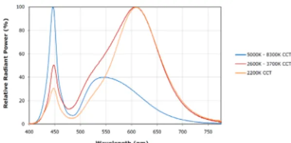
The white light LED used in this study is the Xlamp-XTE White, manufactured by CREE (USA). Its relative radiant power and relative luminous intensity as functions of wavelength and spreading angle, respectively, described in the specifications agree with the results of measurements with a goniometer (JNC Tech Co., Ltd., VA-3001), and we therefore used the angular distributions of luminous intensity and spectral distribution chart in the specifications (shown in Figs.
1 and 2) to obtain basic design data for MR-16 lamp systems. The optical design software packages used were CODE V and LightTools from Synopsys (USA).
Fig. 1. Relative radiant power as a function of wavelength of LED (CREE, Xlamp-XTE White) in the specifications
Fig. 2. Relative luminous intensity as a function of spreading angle of LED (CREE, Xlamp-XTE White) in the specifications
Figure 3 shows a lens layout plot of paraxial rays in a system designed to have an angular distribution of luminous intensity of 40° in an MR-16 lamp with a second lens of thickness d2 at a distance d1 from a lens, which is made of epoxy encasing a LED chip, with a radius of R1and thickness of d0. In Fig. 3, hi(i = 0, 1, 2, 3) refers to a height of a paraxial ray and ui (i = 0, 1, 2, 3) refers to an angle of incidence of the paraxial ray, which corresponds to the half field angle and a half of the angular distribution of luminous intensity. di
(i = 0, 1, 2) refers to the distance between two surfaces. Here, one side of the second lens is designed flat to reduce the mold manufacturing cost and obtain the desired performance with the other side. The value of d0 and the epoxy curvature of R1are already determined by the LED structure. That is, R1 = d0
because the epoxy is dome-shaped. In the basic design, both the refractive indices of the epoxy and the second lens are set to have the same value of n.
LED lamp system Scale: 10.00
2.50 MM
LED
Second Lens
d0 d1
d2 u0=tanθ0
u1 u2
u3=tanθ3
h1 h2
h3
h0=0
Fig. 3. Layout of paraxial rays for initial optical design
Here, the initial half field angle, u0, of the ray originated from the center of a light source, which corresponds to one half of the angular distribution of luminous intensity, may be preset slightly larger than that of the LED. Since the half field angle of the LED is approximately 58° in Fig. 2, a slightly larger value of 70° is entered for u0. From the lens layout plot in Fig. 3, the Paraxial Ray Tracing Method [8] is used to solve for the rear curvature of the second lens, R3, as in Eq. (1) below:
( )
0 3 1 2 0 3
1 1 u u n n d d d R
−
⎟ −
⎠
⎜ ⎞
⎝
⎛ + +
= (1)
In Eq. (1), d0 = 1.5 mm, d1 = 2 mm, and d2 = 4 mm are the initial values mechanically determined for the LEDs by CREE and MR-16 lamps; and the epoxy and the second lens are assumed to have the same refractive index as the material PMMA. Nonetheless, the refractive indices of the epoxy and second lens in PMMA are applied separately in the optimized design.
When the angular distributions of luminous intensity of the MR-16 lamp are 20°, 30°, 40°, and 60°, R3s of the second lens in MR-16 lamps would be calculated from Eq. (1) as -3.2 mm, -3.4 mm, -3.5 mm, and -4.0 mm, respectively.
2.2 Optimized design with aspheric fly- eye lens
Figure 4 shows a diagram of an aspheric surface of a second lens, an initial design of an MR-16 lamp system, and aspheric coefficients for a half field angle of 30°, which corresponds to the half of angular distribution of luminous intensity of 60°. At this point, the Optimization Technique [9, 10] is used to design a second lens with aspheric surface instead of spherical to get the uniform illuminance distributions from the initial design data of the MR-16 lamp system obtained after using the Paraxial Ray Tracing Method in Section 2.1. The aspheric equation of z, which is the height of aspheric surface from the plane base, for the second lens used is shown in Eq. (2) [11].
Fig. 4. Initial optical system with an aspheric surface on fly-eye lens
( )
( ) ( ) ( )
(
+)
+(
+)
+(
+)
+L+
+ + +
+
− +
= +
25 4 2
2 3 2
2 2
22 2 2 2 2
2 2
1 1 1
y x D y x C y x B
y x A y x c k
y x z c
(2)
In Eq. (2), x and y are coordinate on the aspheric surface, c the curvature of the original spherical surface before the aspheric surface is designed, k a conic constant, for which the value -1 is selected initially, and A, B, C, and D aspheric coefficients. c, k, A, B, C, and D from this equation are used as optimization variables during the optimization design process. The diagram on the upper-left side of Fig. 5 shows a lens
layout plot of a LED encased with epoxy and the aspheric second lens, while the graph at the bottom-center shows sag for the second lens.
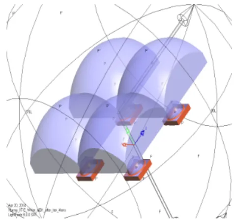
2.3 Optimized design of 2×2 second lens of fly-eye lens type
As a single LED cannot provide enough brightness at displaying objects, we used four LEDs in a 2 × 2 arrangement and located a CCD at the position of 2.5 m away from the lamps to simulate the optical performance of MR-16 lamps with such a light source.
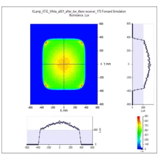
After the simulation of the angular distribution of luminous intensity of 40°, which corresponds to a half field angle of 20°, the illuminance distribution at CCD is obtained as shown in the upper-left graph in Fig. 6.
Here, the color represent the degree of brightness at CCD according to the scale in the bottom-right corner, such that the brighter areas are in red while the darker areas are in blue. The graph in upper-right of Fig. 6 shows the illuminance distribution for the y-axis at X
= 0 and the graph in bottom-left shows the illuminance distribution for the x-axis at Y = 0. As we can see from Fig. 6, the center has slightly higher illuminance;
however, the uniformity ratio, which indicates uniformity of illuminance, is almost constant. Fig. 7 shows simulation results of the angular distribution of luminous intensity at the angular distribution of 40°, which corresponds to the half field angle of 20°.
Fig. 5. Optimized design of optical system of LED lamp with angular distribution of 40° from the horizontal line
Fig. 6. Simulated illuminance distribution of LED lamp with angular distribution of luminous intensity of 40°
Fig. 7. Simulated relative luminous intensity of LED lamp with angular distribution of luminous intensity of 40°
Similarly, the angular distributions of luminous intensity of 20°, 30°, and 60° are simulated and the results are listed, along with those for 40°, in Table 1.
From Table 1, the angular distributions of luminous intensity are within ±3° of the target values of 20°, 30°, 40°, and 60°.
Table 1. Final simulation results of the angular distributions of luminous intensity of 20°, 30°, 40°, and 60°
Specifications of Designed Angular Distributions of
Luminous Intensity
20° 30° 40° 60°
Angular Distributions of
Luminous Intensity 19.6° 32.6° 40.5° 61.7°
3. Fabrication and assembly of second lens for MR-16 lamp
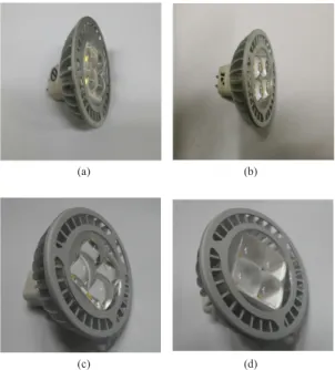
Figure 8 shows photographs of injection molded second lenses of 2 × 2 fly-eye lens type for MR-16 lamps with angular distributions of luminous intensity of (a) 20°, (b) 30°, (c) 40°, and (d) 60°. The molds for these second lenses were fabricated by using the optical variables of the simulated second lens in Section 2. Here, PMMA is used and the gate balance is optimized to design and fabricate a mold that can inject the planer-aspheric convex element of a 2 × 2 fly-eye lens for a total injection time of 140 s or less without distortion.
(a) (b)
(c) (d)
Fig. 8. Photos of injection molded second lens of fly-eye lens type for MR-16 lamps with angular distributions of luminous intensity of (a) 20°, (b) 30°, (c) 40°, and (d) 60°
After designing and fabricating LED electric circuits to fit the second lenses, injected as in Fig. 8, the MR-16 lamps are assembled into each aluminum socket together with a heat sink for cooling, a PCB for the second lens, a LED chip, and a driving circuit to complete the final MR-16 lamp series. Fig. 9 shows photographs of assembled MR-16 lamps with second lens of 2 × 2 fly-eye lens type with the fabricated angular distributions of luminous intensity of (a) 20°, (b) 30°, (c) 40°, and (d) 60°
(a) (b)
(c) (d)
Fig. 9. Photos of assembled MR-16 lamps with angular distributions of luminous intensity of (a) 20°, (b) 30°, (c) 40°, and (d) 60°
4. Performance measurement and analysis of MR-16 lamp
We measured the light transmittance, angular distribution of luminous intensity, luminous efficiency, total luminous flux, and illuminance uniformity of the fabricated MR-16 lamp series in Figs. 9 (a)—(d). Light transmittance is a value obtained by comparing two measurements of total luminous flux, with and without the second lens, using a 2 m integrating sphere.
Therefore, the transmittance of the optical system is
determined by the material of the secondary lens. The transmission referred to in Table 2 is the transmittance of the lens material PMMA. For the angular distribution of luminous intensity, luminous efficiency, and total luminous flux, a goniometer (WITHLIGHT, OPI-370, South Korea) is used to measure ±90° in the left-right direction and ±90° in the up-down direction.
For a spreading angle of illuminance uniformity of 81%, we performed the measurements by defining it as a spreading angle with the same illuminance uniformity of 81% as the Rayleigh's criterion for the illuminance distribution data from measuring the angular distribution of luminous intensity [12]. A yellow tail is visually determined from the color distribution of illuminance shown on a screen 20 m away from the MR-16 lamps.
Table 2. Various performance evaluations of fabricated MR-16 lamps with angular distributions of luminous intensity of 20°, 30°, 40°, and 60°
Specifications of Designed Angular Distributions of Luminous Intensity
20° 30° 40° 60°
Transmittance 92.0%
Angular Distributions of
Luminous Intensity 22.4° 31.1° 37.3° 59.9°
Luminous Efficiency(lm/W) 76.5 75.2 72.0 77.8
Total Luminous Flux(lm) 391 387 380 387
Spreading Angles with Illuminance Uniformity of 81%
3° 15° 22° 49°
The experimental data of angular distributions of luminous intensity, luminous efficiency, total luminous flux, and spreading angle with illuminance uniformity of 81% for the fabricated MR-16 lamp series with designed angular distributions of luminous intensity are listed in Table 2. Graphs of the measured angular distributions of luminous intensity are shown in Fig.
10. As we can see in Table 2, light transmittance is above 90% for every angular distribution of luminous intensity. The angular distributions of luminous intensity for 20° and 30° are measured slightly greater in the range of ±3°, while for 40° and 60° are slightly
less in the range of ±5°. For both luminous efficiency and total luminous flux, we obtained better outcomes compared with market products. Unlike the angular distributions of luminous intensity, 20°, 30°, 40°, and 60°, the illuminance uniformities are measured as 3°, 15°, 22°, and 49°. In other words, illuminance appears uniform within the measured angles and decreases near the angular distributions of luminous intensity.
(a) (b)
(c) (d)
Fig. 10. Measured graphs of angular distributions of luminous intensity graphs for MR-16 lamps with angular distributions of luminous intensity of (a) 20°, (b) 30°, (c) 40°, and (d) 60°
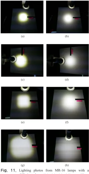
In every case, a yellow tail occurred as shown in Fig. 11 (a), (c), (e), and (g), because the second lenses are designed in aspheric lens form with great refracting power in order to achieve narrow angular distribution of luminous intensity, high luminous efficiency, and high total luminous flux. We placed a diffusion sheet between a LED and the second lens to resolve this issue and the yellow tail disappeared as in Fig. 11 (b), (d), (f), and (h). Installing a diffusion sheet, however, slightly increased the angular distribution of luminous intensity and decreased the total luminous flux, which are assumed to be resolvable by redesigning a portion of lenses and increasing the LED output. From photographs with and without a diffusion sheet in Fig.
11, we could verify the existence of a yellow tail. The actual measurements of angular distribution of luminous intensity, luminous efficiency, and total luminous flux of the MR-16 lamp series with a
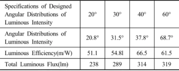
diffusion sheet for each designed angular distribution of luminous intensity are listed in Table 3. From the table, we can see that the angular distributions of luminous intensity of 20°, 30°, and 40° are not much different from the designed values but that of 60° is significantly different. This result indicates that redesigning based on the simulation results, including the effect of a diffusion plate, will be necessary in the future.
(a) (b)
(c) (d)
(e) (f)
(g) (h)
Fig. 11. Lighting photos from MR-16 lamps with a diffusion sheet ((a), (c), (c), (g)) or without ((b), (d), (f), (h))
Table 3. Various performance evaluations of MR-16 lamps with a diffusion sheet
Specifications of Designed Angular Distributions of Luminous Intensity
20° 30° 40° 60°
Angular Distributions of
Luminous Intensity 20.8° 31.5° 37.8° 68.7°
Luminous Efficiency(m/W) 51.1 54.8l 66.5 61.5
Total Luminous Flux(lm) 238 289 314 319
5. Conclusions
We designed, fabricated, and evaluated a second lens for the MR-16 lamp series by using the paraxial ray tracing equation in this paper. Based on the paraxial ray tracing, we made one side of the lighting lenses flat as an initial design value. Since the quantity of light from a single LED lens is insufficient, we combined four LED lenses to make the suitable second lens of 2 × 2 fly-eye type. Then, we used an illumination design program to trace rays and found acceptable illuminance distributions and angular distributions of luminous intensity.
Next, we requested a mold manufacturer to make a prototype of the designed second lens, injection molded the product with PMMA, and made a heat sink and LED circuit to fabricate the MR-16 lamp with a new type of second lens.
The angular distributions of luminous intensity of the fabricated MR-16 of 20° and 30° are measured slightly greater in the range of ±3°, while of 40° and 60° are slightly less in the range of ±5°. The overall differences of the angular distribution of luminous intensity between the design program and the lens molded out from the core mold is less than or equal to
±3°, which means there is almost no performance difference of the second lens between the design program and the fabricated lenses. The light transmittance for 20°, 30°, 40°, and 60° were found to be greater than that of the design values, that is 93.6%, 95.2%, 90%, and 90%, respectively. The illuminance uniformities, unlike the angular distributions of
luminous intensity, are measured 3°, 15°, 22°, and 49°, respectively. The spreading angle with uniform illuminance distribution for the angular distribution of luminous intensity of 20° was as low as 3°. The angular distributions of luminous intensity measured after inserting a diffusion sheet are 20.8°, 31.5°, 37.8°, and 68.7°; the new type of lenses adjoining a diffusion sheet and the second lens will be designed in the future.
In conclusion, we found out that arranging four homogeneous lenses in 2 × 2 fly-eye form would facilitate the design and fabrication of the second lens and the angular distribution of luminous intensity and uniform illuminance distribution would be readily achievable. In addition, it can be assumed that this method has potential commercial value since no cover is needed for MR-16 lamps.
References
[1] Z. Zhenrong, H. Xiang, and L. Xu, "Freeform surface lens for LED uniform illumination", Appl. Opt. 48, pp.
6627-6634, 2009.
DOI: https://doi.org/10.1364/AO.48.006627
[2] D. Malacara and Z. Malacara, Handbook of Optical Design 2th ed., Chapter 9, Marcel Dekker Inc., New York, USA, 2004.
[3] D. Y. Lee, C. H Ko, C. W. Yi, “Compare the efficiency of the reflector and LED secondary lens”, Proceedings of KIIEE Annual Conference (Hoseo University, Korea), p. 60, Nov. 2014.
[4] J. H Kim, M. S. Jung, S. W. Kim, “Aspherical Lens Design of LED surface source”, Proceedings of the Optical Society of Korea Conference (Polytechnic University, Korea), pp. 299-300, Feb. 2007.
[5] K. W. Park, J. Y. Joo, “The Optical Design of Illumination System for LED Stage Lighting Projectors”, Proceedings of KIIEE Annual Conference (Korea), pp.
5-6, May 2014.
[6] S. C. Yoo, K. S. Yoo, D. H. Hyun, “A Study on Aspheric Optics Research for Improving the Luminous Efficiency of the LED MR16”, Journal of the Korean Society of Manufacturing Technology Engineers, pp.
480-487, 2013.
[7] J. H. Park, B. G. Moon, J. H. Yu, “Design of Optical System for LED Lamp using MR16”, Journal of the Korea Academia-Industrial cooperation Society, vol. 13, no. 10, pp. 4725-4732, 2012.
DOI: http://dx.doi.org/10.5762/KAIS.2012.13.10.4725
[8] W. J. Smith, Modern Optical Engineering Third Edition, Chapter 2, SPIE press·Mcgraw-Hill, USA, 2001.
[9] J. H. Jo, “Lamp System with a Single Second-lens Newly Designed by Using the Least Square Method for 4 LEDs”, Proc. SPIE 9131, 91311F, 2014.
DOI: https://doi.org/10.1117/12.2051642
[10] W. J. Smith, Modern Lens Design Second Edition, Chapter. 2, Mcgraw-Hill professional engineering SPIE press, USA, 2005.
[11] E. Hecht, Optics 4th ed., Chap. 9, Addison-Wesley, USA, 2001.
Kyung-duk Chu [Regular member]
•Mar. 2014 ∼ Feb. 2016 : Hannam Univ. Dept. of Photonics and Sensors, MS
•Jul. 2017 ∼ current : Commax Co. Ltd, Senior researcher
<Research Interests>
Optical System Design
Jae Myung Ryu [Regular member]
•Mar. 2004 ~ Feb. 2013 Samsung Electornics Co., LTD., Senior Engineer
•Feb. 2013 ∼ current : Kumoh National Institute of Technology.
Dept. of Opt. Eng., Professor
<Research Interests>
Optical Design, Geometrical Optics
Chun-Gang Hong [Regular member]
•Mar. 1997 ∼ current : Kang Dong Tech Co. Ltd, President
<Research Interests>
Plastic Injection Mold, LED Illumination Component
Youn Hong Jeong [Regular member]
•Mar. 2015 ∼ current : Kookje Univ. Dept. of Optometry, Assistant Professor
<Research Interests>
Optical Science, Optometry
Jae Heung Jo [Regular member]
•Mar. 1987 ∼ Feb. 1992 : Korea Research Institute of Standards and Science; KRISS, Senior researcher
•Mar. 1992 ∼ current : Hannam Univ. Dept. of Photonics and Sensors, Professor
<Research Interests>
Optical Metrology, Optical System Design