http://dx.doi.org/10.5369/JSST.2014.23.3.149 pISSN 1225-5475/eISSN 2093-7563
An Analysis of 2D Positional Accuracy of Human Bodies Detection Using the Movement of Mono-UWB Radar
Mohammad Ahangar Kiasari
+, Seung You Na, and Jin Young Kim
Abstract
This paper considers the ability of counting and positioning multi-targets by using a mobile UWB radar device. After a background subtraction process, distinguishing between clutters and human body signals, the position of targets will be computed using weighted Gaussian mixture methods. While computer vision offers many advantages, it has limited performance in poor visibility conditions (e.g., at night, haze, fog or smoke). UWB radar can provide a complementary technology for detecting and tracking humans, particularly in poor visibility or through-wall conditions. As we know, for 2D measurement, one method is the use of at least two receiver antennas.
Another method is the use of one mobile radar receiver. This paper tried to investigate the position detection of the stationary human body using the movement of one UWB radar module.
Keywords: Background subtraction algorithm, Gaussian mixture method, Human motion detection, Mono-UWB radar module
1. INTRODUCTION
The IR-UWB is a technology of ultra wide band impulse signal to detect targets by transmitting and receiving the impulse signal.
Computer vision has some limitations in poor visibility condition at night, in haze, or fog and smoky areas, while UWB radar has particularly acceptable ability in poor visibility or through-wall condition and also has little been affected by dust and moisture.
However, the complex scattering behaviour of UWB waveforms poses additional signal processing problems such as removing noise, background subtraction, detecting position and tracking.
Singular value decomposition (SVD) [1] and Kernel density estimation (KDE) are some specific methods for removing clutters. SVD method is not adaptive for complex areas and KDE is time-consuming for real time applications [3]. In this paper, Adaptive Background Subtraction based on exponential averaging has been used [2]. This method has robust performance and low complexity and also has strong capability in complex and changeable backgrounds. 1D localization is the next important
task. The returned UWB radar signal of human body consists of multipath-components presents each part of the human bodies [4].
The Clean Algorithm (CA) can be applied for separating these components and computing Time of Arrival (TOA) [5-7]. In order to compute TOA for multiple targets, Maximum Likelihood (ML) of Gaussian Mixture Model (GMM) has been applied [2]. This paper used the Novelda radar module which has one transmitter and one receiver antenna.
The UWB radar of this paper is working in 4.8 GHz. Federal Communication Commission (FCC) regulates the power of radar from 3.1 to 10.6 GHz in −41.3 dBrn/MHz. The performance of UWB radar is not outstanding as 24 GHz short range radar sensor.
One way to obtain Two-dimensional coordinates of the human body is the installation of two or more receiving antennas around the objects. These ways have financial costs. As the module has only one receiving antenna, the best way to obtain a Two- dimensional coordinate map is the sweeping of the UWB beam over the area of interest.
Target localization and tracking has been already investigated for one dimensional area by one sender and one receiver radar module [14,15]. In [9-11] single target localization by using one sender and multiple receivers has been investigated. Some other articles focused on two dimension areas by multiple radar modules [12].
The coordinates of the targets could not be calculated by one radar module that can only measure a radial distance from converting time-of-arrival (TOA) [13]. On the other hand, using School of Electronic and Computer Engineering, Chonnam National
University, 77 Yongbong-ro, Buk-gu, Gwangju 500-757, Korea
+
Corresponding author: [email protected] (Received: Mar. 3, 2014, Accepted: May. 22, 2014)
This is an Open Access article distributed under the terms of the Creative Commons Attribution Non-Commercial License (http://creativecommons.org/
licenses/bync/3.0) which permits unrestricted non-commercial use, distribution,
and reproduction in any medium, provided the original work is properly cited.
multiple radar modules can increase the costs sharply. In addition, in some emergency application such as destroyed buildings and rough grounds, installation of multiple statistic radar modules could be difficult and time consuming. Therefore one moving radar module can be suitable and also a cheapest way for detecting the coordination of targets. This paper tried to use one moving UWB radar module to compute the coordination of multiple targets. Low ability for counting the moving human is the disadvantage of this method [8]. In multiple target cases, unreal (ghost) targets will be appearing and make some difficulties for detection of the real positions [16]. This paper proposed one sufficient algorithm based on fuzzy K-means clustering for distinguishing between real and unreal targets.
The rest of this paper is organized as follows. Section 2 outlines Removing Noise and Direct Waves between TX-RX, followed by Background Subtraction Algorithm in Section 2.2. Section 2.3 discusses about the Position Detection. The experimental results are introduced in Section 3. Finally, Section 4 concludes the paper.
2. POSITION ESTIMATION
In this section, we investigate removing noise and direct waves between TX-RX, background subtraction and position detection.
2.1 Removing Noise and Direct Waves between TX-RX Removing noise is the first step of processing of received data from radar module. Fig. 1 shows the time domain of one frame of receiving signals from the environment by the radar antenna.
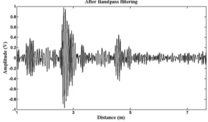
Reflected waves from targets have been located in limited middle frequency interval. Other components of raw signal will be related to noise and direct waves between TX-RX. Therefore, the noise and direct waves can be removed by one suitable band-pass
filter. In an instance, Fig. 2 illustrates the output of this band-pass filter. This figure shows the reflected wave from the environment that it includes two human targets
2.2 Background Subtraction
There are several methods for background subtraction such as KDE and SVD. The problem of these methods is that they need large number of previous frames for background definition. Since in this paper, we are utilizing mobile UWB radar module, one background subtraction method with suitable updating ability is needed. The Background subtraction method presented in [1] has a sufficient and fast algorithm for removing clutters. The foundational theory of this method is based on exponential averaging. One memory buffer is defined for holding n initial frame of environment without any moving target. As we know these frames contain clutters and noise. Therefore the noise level can be achieved by using these initial frames. Fig. 3 illustrates the main structure of this algorithm.
y(k) is the input and x(k) is the output and desired background.
K is a constant that has been defined to control the speed of updating background, (0 < K < 1). This algorithm has good ability for detecting the little motions of stationary human body. These motions are coming from breathing, heart beating and etc. In this case, radar module has been moved from one location to another one and radar module will be paused for a few seconds at each location. This pause is necessary for detecting the human body.
Fig. 1. One raw frame.
Fig. 2. One frame after band-pass filtering.
Fig. 3. The diagram of background subtraction filter.
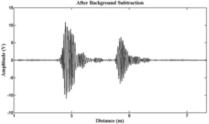
Fig. 4 shows the output of background subtraction algorithm for two human targets.
2.3 Position Detection
The UWB radar signal which reflected from a human body includes multiple path components, as the impinging UWB electromagnetic wave reflected from different human body parts at different times with various amplitudes (depending on the distance of the body part to radar, and the size and material of the reflecting part). Thus, the returned UWB radar signals v (t) can be approximated by (1):
(1)
a
iand n
irespectively represent the amplitude and time-of arrival of component of the receiving signal and p(t) is elementary
waveform (template waveform).
Using clean algorithm, the reflected wave from each person must be disintegrated to some source waveform with different amplitudes. Also, by using clean algorithm, the position accuracy of two closed targets could be enhanced. Fig. 5(a) shows the template waveform. Fig. 5(b) and Fig. 5(c) show the detection of two human bodies before and after CA.
2.3.1 Gaussian mixture method
For computing the position of moving objects and detecting the new current target the expectation maximum of the weighted Gaussian mixture method can be used. This method also helps us to distinguish much closed targets. Usually the maximum amplitude of the reflected wave presents the position of human trunk contains abdomen and Chest. It means that each component of reflected wave has different value to illustrate the human position. Thus, for increasing accuracy of human position I defined a weight for each point of reflected waves.
According to (1), it seems that a
ican do this task well. But there is one serious problem. The amplitude of receiving waves has decreased tendency from close to far distance. For solving this problem, this paper proposed that the radar range might be separated to n small area virtually. In these small areas, we can assume that the reflected human body`s signal has same voltage level approximately. Thus, in these small areas, a
iwould be a suitable coefficient to apply by GMM formulas. n relates to the radar range and the resolution. Steps 1 to 6 define the GMM algorithm:
Step 1: Initialization of the mean and standard deviation values of each Gaussian functions which are presenting the target.
Step 2: Computing the Gaussian mixture functions and Expectation maximum for each cluster.
Step 3: Updating the Gaussian mixture functions by using the output data of the clean algorithm for one frame.
(2)
(3) Where is the prior probability function of the cluster , p is the posterior function, c is the number of clusters.
Equation below will be used for the weighted Gaussian mixture method:
(4) v t ( ) a
ip t ( – n
i)
i 1= L
∑
=
P w (
jx
k) p x (
kw
j)P w ( )
jp x (
kw
i)P w ( )
i ci 1=
∑ ---
=
P w ( )
jc j=1
∑ = 1
P ˆ w
j( ) w
j( )
μˆ
j( ) i
P w (
jx
k)x
k Nk=1
∑
P w (
jx
k)
N k=1
--- ∑
= Fig. 4. One frame after background subtraction filtering.
Fig. 5. The results before and after clean algorithm (CA). Template
waveform (a), before CA (b), after CA (c).
(5)
Where N is the number of points which have been shown in Fig. 5(c). and are the new mean and standard deviation of the cluster at iteration.
Step 4: Iteration criterion: If ( >threshold T1) go to step 3.
Step 5: Final will represents the position of target.
Also this value is the initial position of the target in next frame.
Step 6: Considering the new moving target/targets. In this step, we need to consider new targets. I assume that there are C moving targets, therefore we have:
(6) i presents the number of clusters and is the summation of probabilities of for each cluster. The missed points can be identified by considering the values of . if there are missed point in step 6, we should increase the number of clusters and go back to step 3.
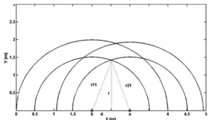
Finally, this group of means can present all the targets. Until now, the radial distances of the targets have been obtained by using one UWB radar module. The problem is that one radar module is not enough to determine the two-dimensional coordinate of targets. According to Fig. 6, for solving this problem, radar module should be moved to other positions to capture new frames from different sides. By using the measurements at positions , the dimension of measurement can be increased to 2-dimention.
2.3.2 Target existence algorithm
According to the Fig. 6, at situation#1, radar has detected k targets. Therefore there is the position array R
1=
. And also can be computed
similarly. Therefore there are n arrays with different lengths. The temporary positions of moving radar is shown in Fig. 6:
Position array at situation#1 = Position array at situation#2 =
Position array at situation#3 = (7)
m is the number of targets. By using the position arrays at situation #1 and #2 and equations (8), the probable target positions can be computed.
, , (8)
Parameters d, , are defined in Fig. 7. D is the distance between two temporary positions of radar module. x and y are the coordinate of target, a and b are the first and second positions of moving radar module. Also, we should follow this method for other pairs of the position arrays ( and , and ).
2.3.3 Ghost (unreal target) effect:
The IR-UWB Radars give distance information to some target without identifying the target. Therefore, in multi-target cases, there are some real targets and some unreal (ghost). Let to consider one example. There are two targets at (500 cm 200 cm), (400 cm 300 cm) and also first and second temporary position of the radar module are at (600 cm 0 cm) and (400 cm 0 cm) respectively. The Fig. 8 shows the ghost effect clearly. One radar detects two targets by introducing two distances. But in this figure, there are two real targets and two ghosts. Obviously by increasing the number of targets, the number of ghosts will increase.
By carrying the radar module to other temporary positions, the positions of real targets will be approximately fixed. While, the ghosts have variable positions. Fig. 9 illustrates this fact.
εˆ
j( ) i
P w (
jx
k) x (
k– μˆ
g( ) i ) x (
k– μˆ
g( ) i )
tN k=1
∑
P w (
jx
k)
N k=1
--- ∑
=
μˆ
j( ) i εˆ
j( ) i
j
thi
thμ
ji 1+– μ
jiμˆ
j( ) i j
thj
thγ
k cP
i 1=
( ) i
( w
ix
k)
∑
=
γ
kx
kγ
kpos1 pos2 , , , … posn
r
11, r
12, , … r
1k[ ] R
2, , … R
nr
11, r
12, , … r
1m[ ]
r
21, r
22, , … r
2m[ ]
r
n1, r
n2, , … r
nm[ ]
d ( ( r
112– r
212) D +
2) --- 2D
= x = b + d y = ( r
112– d
2)
2r
11r
21R
2R
3R
1R
3Fig. 6. The present the temporary. position of moving radar.
pos1 pos2 , , , … posn
Fig. 7. Computing the position of targets using two position arrays
R
1and R
2.
By using this fact, this paper proposed a method to recognize the real position. In well separated target cases, computing the position of the ghosts and the targets is not hard job, but in closed target cases, we need to apply some sufficient method to compute the local maximum of probability function which is presented in Fig. 10.
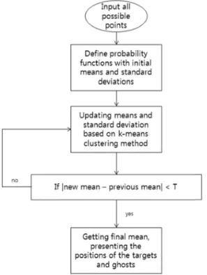
The algorithm which is used to compute the position of ghosts and targets is based on Fuzzy k-means clustering (FKMC). Fig. 12 shows the algorithm of finding the position of the targets and the ghosts. Firstly, some 2D Gaussian functions with initial means and standard deviations have been defined. This initial means include all the possible points which are shown in Fig. 10.
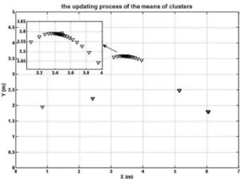
According to FKMC method, this initial means will be updated until all the means of the clusters converge to final positions. Fig.
11 shows the process of the updating means. And now, there are
some clusters with final means that present the position of targets and ghosts. Likewise, at real target positions, the concentration of points is more than other places. According to this fact, the formula (9) is utilized to evaluate each cluster.
(9)
m is the number of all detected point, j is the number of clusters, V is the value function of the clusters, GF is the final Gaussian function of each cluster and presents the position of point.
Therefore, the clusters which have highest value (V) will present the position of real targets. This algorithm is presented in Fig. 13.
By the way, the mean of each cluster could be affected by the other clusters around it`s nearby. So for removing this effect, the new means can be computed by the members of each cluster separately. Fig. 14 shows the points are involved for computing
V j ( ) GF pos i ( ( ) )
i=1 m
∑
=
pos i ( ) ith
Fig. 8. Probability functions of targets and ghosts.
Fig. 9. Figures a, b, c and d are the probability functions of targets and ghosts during 4 measurements. According to Fig. (6):
pos1= [300 0], pos2= [600 0] in (a), pos1= [300 0], pos2=
[500 0] in (b), pos1= [400 0], pos2= [600 0] in (c), pos1=
[500 0], pos2= [600 0] in (d).
Fig. 10. This initial means includes all possible points. Solid cir- cular dots present the real positions of the targets.
Fig. 11. The convergence process of the means.
the final means for each cluster. This means, there will be two groups of points and each group includes three points. The means of each group of points presents the final target position. The final result of this all process is illustrated by Fig. 14.
3. RESULTS AND DISCUSSIONS
In this section, some experimental results are presented. The
initial position of antenna is (1.5 m, 0 m) and then antenna will be replaced to second ([2.5, 0]) and third position ([3.5, 0]) respectively. At each position, the antenna was kept fixed for 10 Fig. 12. The algorithm of finding the positions of the targets and
ghosts, based on Fuzzy k-means clustering. T is a thresh- old.
Fig. 13. The algorithm of finding the real positions of the targets.
Fig. 14. The selected points for improving the positions of the tar- gets.
Fig. 15. The final target positions.
Fig. 16. The temporary positions of one radar module.
seconds. The map of environment and temporary positions of radar modules are shown in Fig. 16:
The pos1, pos2 and pos3 present the temporary position of the moving mono-UWB radar. The initial position of radar module is pos1. The radar module has been moved 1 meter to be located at next position. In each location, radar module will be fixed
about 10 seconds to collect enough samples. In this case, there are two clusters which are related to the targets. By one pair of radar module we can compute the coordination of each target.
For example, Fig. 17 shows the all possible point which are obtained by collecting data from temporary positions pos1, pos2 and pos3.
Using the algorithm presented in Fig. 12 and Fig. 13, the real target positions will be achieved. These results are shown in Fig. 18.
The average error function is defined by:
(10)
In Tables 1 and 2, ‘wrong detection’ presents the detection of wrong cluster (unreal target) as a real target. Clearly, if we would increase the distance between two positions of radar antenna, we will have better results, but on the other hand the undesirable ghost effect will be decreased.
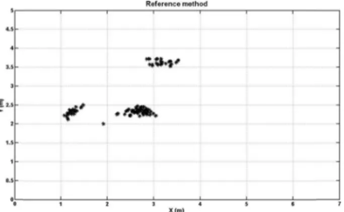
Fig. 19 shows the means of chosen points of each cluster while the Fig. 18 directly presents the means of each cluster.
And also, in this paper, another method has been applied which Average Error 1
50 ---
50( P
x– p
xi)
2+ ( P
y– p
yi)
2i=1
( )