638 http://dx.doi.org/10.9713/kcer.2015.53.5.638
PISSN 0304-128X, EISSN 2233-9558
Porous Electrodes with Lower Impedance for Vanadium Redox Flow Batteries
Su Mi Park and Haekyoung Kim†
School of Materials Science & Engineering, Yeungnam University, 280 Daehak-Ro, Gyeongsan, Gyeongbuk 38541, Korea (Received 25 June 2015; Received in revised form 20 July 2015; accepted 1 August 2015)
Abstract − Vanadium redox flow batteries (VRFBs) have been investigated for their potential utility as large energy storage systems due to their advantageous performances in terms of long cycle life, high energy efficiency, low cost, and flexible design. Carbon materials are typically used as electrodes in redox reactions and as a liquid electrolyte support.
The activities, surface areas, and surface morphologies of porous carbon materials must be optimized to increase the redox flow battery performance. Here, to reduce the resistance in VRFBs, surface-modified carbon felt electrodes were fabricated, and their structural, morphological, and chemical properties were characterized. The surface-modified carbon felt electrode improved the cycling energy efficiencies in the VRFBs, from 65% to 73%, due to the improved wettability with electrolyte. From the results of impedances analysis with proposed fitting model, the electrolyte-coupled polariza- tion in VRFB dramatically decreased upon modification of carbon felt electrode surface. It is also demonstrated that the compressibility of carbon felt electrodes was important to the VRFB polarization, which are concerned with mass trans- fer polarization. The impedance analysis will be helpful for obtaining better and longer-lived VRFB performances.
Key words: Vanadium Redox Flow Battery, Surface Modification, Carbon Felt, Impedance, Efficiencies
1. Introduction
Energy conversion technologies, in which renewable energy sources are converted to electrical energy, have been developed in response to climate change. Such technologies require energy storage systems to enable flexible usage. Energy storage systems require a high charge capacity, long cycle life, rapid response time, and low cost. Redox flow batteries (RFBs) are rechargeable storage systems in which an electrolyte containing two dissolved chemical components is sup- plied to a redox reaction. RFBs are advantageous in that the liquid electrolyte tanks are separable and the longevity is nearly unlimited compared with conventional rechargeable batteries. RFBs, however, deliver relatively low power levels and require complicated operation technologies. Vanadium redox flow batteries (VRFBs) were devel- oped and commercialized to exploit the use of a single metal ion spe- cies in both the anodic and cathodic electrolyte, thereby reducing contamination and capacity depletion. The electrochemical half- reactions of a VRFB are as follows.
positive electrode = VO2+ + H2O VO2++ 2H+ + e- negative electrode = V3+ + e- V2+
VRFBs use vanadium ions dissolved in aqueous sulfuric acid, and carbon materials are used as electrodes, current collector, and electrolyte supports. Ion exchange membranes are positioned between the anodic and cathodic carbon electrodes to form both the separators
and ion transport path [1,2]. The performances of VRFBs depend on the electrodes and separators, and the activities of electrodes may be turned to increase the performance and promote the V+4/V+5 and V+2/V+3 redox reactions at the electrode surface [3-5].
VRFB performances may be improved through the use of a car- bon felt with a good electronic conductivity, a high electrochemical activity, and good stability. The electrochemical activity may be increased by increasing the carbon electrode surface area and wet- ting the carbon felt with the electrolyte. Carbon felt, however, tend to be highly hydrophobic, leading to poor reaction kinetics between the electrolyte and the redox ion couples [6-9]. The activities of the car- bonaceous electrodes surfaces may be increased by treating the elec- trodes under a variety of conditions [10-12]. Incorporating additional treatments into the electrode preparation processes can notably enhance the electrochemical activity of a carbon felt by changing its surface chemistry. The relationship between the surface properties and the electrochemical performance of a carbon felt electrode have not previously been clarified. The electrochemical events within a VRFB that rely on the physicochemical surface properties of a carbon felt must be investigated. For example, charge transfer at the electrode, the electrolyte coupled reactions, and mass diffusion reactions in electrolyte at the electrode may rely on the materials properties and operation conditions within a VRFB. VRFBs are technically similar to both fuel cells and to batteries. Many studies have examined the properties of electrochemical devices using electrochemical imped- ance spectroscopy (EIS), which characterize the correlations between the parameters (materials properties, processes, operation conditions, etc.) and electrochemical performances [13,14]. Few studies have specifically addressed RFBs [15-17]. Studies that examined RFBs used an equivalent circuit composed of two resistance and constant
†To whom correspondence should be addressed.
E-mail: [email protected]
This is an Open-Access article distributed under the terms of the Creative Com- mons Attribution Non-Commercial License (http://creativecommons.org/licenses/by- nc/3.0) which permits unrestricted non-commercial use, distribution, and reproduc- tion in any medium, provided the original work is properly cited.
phase element of capacitance in their analysis [15]. Furthermore detailed studies of VRFBs may guide the development of high-performance devices.
To this end, the effects of surface modifications on structural and electrochemical properties of a carbon felt electrode were examined.
The electrochemical performances were analyzed using EIS to char- acterize the elements of a proposed equivalent circuit as a function of the operation conditions and cell structure.
2. Experiments
Commercial carbon felt (NEWELL, Korea) was used as the elec- trode (5.4 cm × 6.0 cm × 0.3 cm in size) in this work. The surface of the carbon felt was oxidized by heating at 450 oC for 5 h under an air atmosphere. The morphology of the felts was characterized by col- lecting optical spectroscopy images (Bx 51, Olympus, Japan) and scanning electron spectroscopy images (SEM, S-4100, Hitachi) of the bare carbon felt (CF No HT) and the heat-treated carbon felt (CF 450-5). The chemical properties of the surfaces were characterized using X-ray Photoelectron Spectroscopy (XPS, K-Alpha, Thermo scientific) analysis. The wettability of the electrolyte was character- ized by measuring the wetting angle formed by an electrolyte droplet on the surface of the CF No HT or CF 450-5 felts. The electrical con- ductivities were measured using a WEIS system (Wonatech, Korea).
The VRFB performances of the carbon felt electrodes were evalu- ated using the flow cell shown in Fig. 1. The performance test included a flow cell, two peristaltic pumps, two electrolyte reser- voirs and Viton® tubing. Each reservoir included 40 mL of the elec- trolyte, and each electrolyte was circulated at 18, 36, and 54 cc·min-1. The starting electrolyte solution was 1.8 M VOSO4 electrolyte in 3M H2SO4. The anolyte and catholyte were prepared by charging the starting electrolyte to 1.8 V at 50 mA·cm-2 using the flow cell. Nafion 115 membrane was used as a separator. The untreated carbon felts (CF No HT) and heat-treated carbon felts (CF 450-5) were used as the electrodes, and the compressibility effects of electrode were char- acterized by assembling and testing two and three of carbon felts.
The VRFB cell prepared with two of CF No HT was labeled as CF2 No HT; the cell prepared with three CF No HT electrodes was labeled CF3 No HT; and the cell prepared with two CF 450-5 electrodes was
labeled CF2 450-5. The performances were evaluated by charging to 1.8 V at 50 mA·cm-2 and discharging to 0.8 V with 25, 50, 75 and 100 mA·cm-2. The VRFB cycle performances were measured by charging to 1.8 V at 50 mA·cm-2 and discharging to 0.8 V at 50 mA·cm-2. The impedance measurements were carried out using a WEIS sys- tem (Wonatech, Korea) over the frequency range from 100 kHz to 0.1 Hz under an applied AC voltage amplitude of 100 mV.
3. Results and Discussion
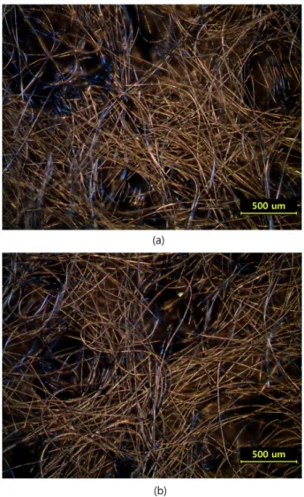
The optical images of the CF No HT and CF 450-5 are shown in Fig. 2, which reveals that the carbon fibers formed three-dimen- sional hollow structures and the open spaces were randomly shaped.
The optical images did not readily distinguish between the morpho- logical differences; however, the SEM images shown in Fig. 3 revealed that the CF 450-5 surface was oxidized during heat treat- ment to increase the surface area. The wettability of the carbon felt electrode is shown in Figure 4. As the electrolyte was dropped on the surface of the CF No HT felt, the electrolyte formed a wetting angle of 145o; however, the electrolyte droplet applied to the CF 450-5 felt spread immediately onto the surface of carbon felt. The wettability
Fig. 1. Schematic diagram of VRFB. Fig. 2. Optical microscopic images of (a) CF No HT and (b) CF 450-5.
of the carbon felt improved as a result of the surface modification process, thereby improving the electrolyte supply in the VRFB. The electrical conductivity, however, decreased from 96.1 to 77.43 S·cm-1 after introducing the surface modification.
XPS studies verified the surface chemical states of the CF No HT and CF 450-5 felts. Fig. 5 shows the XPS spectra of the C and O ele- ments obtained from the CF No HT and CF 450-5 felts. The XPS spectra were analyzed using a de-convolution fitting method of obtained C 1s and O 1s spectra. The O 1s peak was fit using three peaks over the range of 531-535 eV. The peak around 533 eV was attributed to the phenolic (C-O) groups, and the peak around 531 eV could be assigned to the carboxylic or carbonyl (C=O and/or C-O-C) groups.
Adsorbed water and some chemically absorbed oxygen may have contributed to the additional peak around 535 eV [18]. As shown in Fig. 5, the phenolic groups (C-O) around 533 eV and the peaks attributed to adsorbed water and chemically adsorbed oxygen around 535 eV were negligible in the spectrum obtained from the bare car- bon felt, CF No HT. The bare carbon felt displayed very hydropho- bic properties; however, CF 450-5 included an increase in the peak intensity around 535 eV, which improved the wettability. After heat treatment, the peak intensities corresponding to the C-O peak (O 1s-A)
and C=O peak increased. The relative peak intensity of the phenolic (C-O) groups dramatically increased; however, the peak intensities of the carboxylic or carbonyl (C=O and/or C-O-C) groups only slightly increased. Heat treatment formed additional phenolic (C-O) groups and carboxylic or carbonyl groups (C=O) on the surface of the carbon felt, which increased the surface wettability. The carbon felt surface could be readily modified by evolving CO and/or CO2 under an air atmosphere at high temperatures. The relative molar ratio of carbon and oxygen could be estimated from each peak based on the areal ratio between the C 1s and O 1s peaks. As shown in Fig.
5(c), more functional groups formed after heat treatment. The carbon felt could be readily oxidized during a heat-drive surface modification process, and carbon-oxygen functional groups, including carboxylic or carbonyl groups (C=O) and phenolic groups (C-O), were observed on the surface in greater numbers compared to the bare carbon felt, CF No HT. The relative ratio of the C-O to C=O groups increased as the surface modifications present on the carbon felt were incorpo- rated. The carbon-oxygen functional groups affected the wettability due to improvements in the hydrophilicity, which improved the elec- trochemical event relating to electrolyte coupled polarization.
The electrochemical properties relating to the surface properties Fig. 3. Scanning electron microscopy images of (a) CF No HT and
(b) CF 450-5. Fig. 4. Wettability of electrolyte on the surface of electrode.
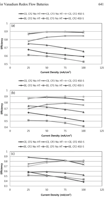
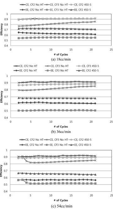
and the electrode compressibility were investigated by measuring the performances of VRFBs prepared with various carbon felt elec- trodes. Fig. 6 plots the efficiencies of VRFBs prepared with the CF2 No HT, CF3 No HT, and CF2 450-5 electrodes under discharging currents of 25, 50, 75 and 100 mA·cm-2 after charging at 50 mA·cm-2. Fig. 7 shows the cyclic efficiencies of the VRFBs prepared with the CF2 No HT, CF3 No HT, and CF2 450-5 electrodes at each flow rate. Fig. 8 shows the performances of the charge-discharge charac-
teristic as a function of the current density. The CF2 450-5 VRFB dis- played a 90 % columbic efficiency and a 73% of energy efficiency at 18cc·min-1. As the flow rate increased, the efficiency decreased, demonstrating that the performances depended on the operation con- ditions, including the flow rate and discharging current. The cyclic columbic efficiencies of the VRFBs prepared with CF2 No HT or CF2 450-5 were comparable; however, the energy efficiencies in CF2 450-5 improved. As the surface was modified via heat treatment, the cyclic energy efficiency performances of the VRFBs increased from 65% to 73%. The VRFB prepared with CF2 450-5 exhibited the highest efficiency measured in all case except at a flow rate of 54 cc·min-1, with discharging at a low current. The VRFB prepared with CF2 No HT exhibited higher columbic efficiencies and lower energy efficiencies than the VRFB prepared with CF2 450-5 at 54 cc·min-1. The higher flow rate induced wettability improvement and the Fig. 5. O 1s spectra obtained by XPS before and after the surface
modifications; (a) bare carbon felt, (b) mild oxidation at 450oC for 5 h under air atmosphere and (c) ratio of func- tional group.
Fig. 6. Efficiencies of VRFB at (a) 18 cc/min, (b) 36 cc/min, and (c) 54 cc/min of electrolyte flow rates respectively (CE; colum- bic efficiency, EE; energy efficiency).
higher electrical conductivity in the CF2 No HT felt provided a higher columbic efficiency; however, the charging/discharging charac- teristics illustrated in Fig. 8 revealed that the voltage during discharg- ing in the CF2 450-5 VRFB was much higher than that in the CF2 No HT VRFB. The better performances as a result of the improved electrode wettability may reduce cross-over of the vanadium ions through membranes. This effect is related to the electro-osmotic drag effects. Poor VRFB performances are accompanied by the easy transfer of unreacted vanadium ions across the membrane, which may reduce the energy efficiency of the device. The results shown in Fig. 6-8 reveal that the VRFB performances improved as the surface of the carbon felt electrodes were modified, leading to higher sur- face areas and improved electrolyte wetting properties.
The effects of the electrode surface modification were investi- gated using impedance analysis with an equivalent circuit as shown in Fig. 9. The measured impedances were fitted using the proposed equivalent circuit. The VRFBs include the polarization of ohmic, charge transfer, and mass transfer, as the electrolytes flow. VRFBs are technically similar to both fuel cells and to batteries. Several elec- trochemical events occur within a VRFB during operation. Ohmic polarization results from the resistance of the membrane, liquid elec- trolyte, and the electrode between two bipolar plates. The electrolyte flow through the porous felt electrodes causes mass transfer polariza- tion. Charge transfer polarization at the anode and cathode electrodes may result from electrode activity, electrolyte-coupled reaction (reac- tion that depend on the electrolyte wetting on the electrode surface), and charge transfer within the liquid electrolyte. In this study, the equivalent circuit with five RQ (resistance and constant phase ele- ment) impedance elements connected in series (an inductor, resistor, and five elements) was proposed. Each of the proposed equivalent circuit elements associated with separate electrochemical events in the VRFB. The appropriate impedance model isolated the mass dif- fusion and charge transfer contributions to the polarization [13-15]
from the structural and morphological properties of the carbon felt assembly.
The fitting results shown in Fig. 10 revealed the each element val- ues of VRFBs prepared with CF2 No HT, CF3 No HT, and CF2 450-5 under a flow rate 36 cc·min-1 and without a current load (OCV). The fitted results are quite well matched with measured data; however, the fit results for the CF2 450-5 VRFB did not agree well the curve in the high frequency range, possibly due to the inductance of wire interfer- ence [19]. The total resistances of the VRFB prepared with the CF2 450-5 were much lower, 0.27 Ω, than the values obtained from a VRFB prepared with the CF2 NO HT electrode (1.62 Ω). As shown in Figure 10, VRFB prepared with the CF2 450-5 exhibited the much lower total resistance value, regardless of the flow rate.
Fig. 7. Cyclic Efficiencies of VRFB at (a) 18 cc/min, (b) 36 cc/min, and (c) 54 cc/min of electrolyte flow rates respectively.
Fig. 8. Charge-discharge curves for VRFBs. Fig. 9. Equivalent Circuit.
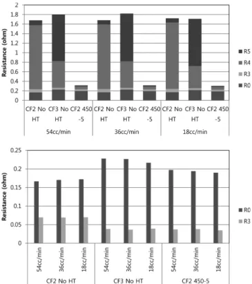
The fitting results revealed that two of the resistances, R1 and R2, were equal to zero, indicating that the R1 and R2 elements could be removed, and the equivalent circuit for VRFB could be simplified to a series of three elements. Charge transfer within the anodic and cathodic electrolytes, R1 and R2 elements, could be ignored due to fast ionic transfer in the liquid electrolyte. Fig. 11 and 12 revealed that R0 and R3 varied slightly among the VRFBs, and R4 and R5 changed dramatically. The R0s measured in each VRFB were similar in value under all flow rates. The value of R0 measured in the CF2 450-5 VRFB was slightly higher than the corresponding value mea- sured in the CF2 No HT VRFB due to an increase in the resistance upon oxidation of the carbon felt. R0 measured in the CF3 No HT VRFB reached the highest values measured due to the high resis- tance of lower electrolyte wetting in carbon felts. Although highly compressed carbon felts may increase the electrical path, ionic elec- trolyte filling in these carbon felts was reduced and the polarization was increased. Here, the ohmic resistance in the VRFBs was com- posed of contributions by the membrane, carbon felt electrode, and electrolytes adsorbed onto the carbon felt surface. The values of R3 in each VRFB were similar under flow rates, as shown in Fig. 11.
The values of R3 differed only slightly with the felt type. The CF3 No HT and CF2 450-5 electrodes displayed slightly lower values of R3 compared to the pristine carbon felt, possibly due to the carbon felt activity resistance, which increased during the surface modifica- tion process or due to compaction of the carbon felt structures.
The values of R4 and R5 were examined as a function of the phys- ical properties of the felts. CF2 and CF3 indicate the electrode com- pressibility, where CF3 indicates a denser electrode that produced a
Fig. 10. Bode plots of VRFBs prepared with (a) CF2 No HT, (b) CF3 No HT, and (c) CF2 450-5.
Fig. 11. Results of impedance analysis with flow rates under open cir- cuit voltage of VRFBs.
greater number of electrical contacts between the carbon felt and the current collection plates. A comparison of the results obtained from the No HT and 450-5 felts revealed the effects of the electrode surface area and the coupled reactions on the electrolyte wettability. Here, the compressibilities of the electrodes in CF2 and CF3 were controlled, and the CF3 No HT VRFB formed a more compressed denser elec- trode assembly. The R4 values obtained from the CF3 No HT VRFB was lower than that obtained from the CF2 No HT VRFB. The value of R5 obtained from the CF3 No HT VRFB was higher than that obtained from the CF2 No HT VRFB. R4 appeared to reflect the dependence of the electrolyte-coupled reactions on the surface area, and the trends in R4 agreed with the results obtained from the CF2 450-5 VRFB. The values of R5 were dramatically higher in the CF3 No HT VRFB. The diffusion of electrolyte may be retarded due to the compressed morphologies, which increased the R5 values.
The CF2 450-5 VRFB yielded quite low R4 and R5 values, which were inferred to reflect the main factors that reduced the total resistance.
The relationship between the carbon felt surface properties and the electrolyte was explored by characterizing the resistance changes resulting from oxidation of the carbon felt surface via heat treatment.
The electrochemical reaction relating to the carbon felt surface and electrolyte was the electrolyte-coupled reaction shown in Fig. 12(b).
Surface modification significantly reduced the R4 values, indicating
that R4 related to the electrochemical events that were affected by the carbon felt surface properties. The results obtained from three types of electrodes revealed that R4 was related to an electrochemi- cal reaction coupled with the electrolyte wettability on the electrode surface, and R5 was related to the electrochemical reactions involv- ing mass diffusion within the electrode.
In this study, the VRFB operation parameters were varied to inves- tigate the physical events underlying the impedance responses, and a five-element model was used to describe the electrochemical events.
The electrolyte-coupled reaction and mass transfer within the VRFBs reduced polarization. The physical meaning of each element in this work may inform the optimization of materials and processes for use in VRFBs. The degradation mechanisms may also be analyzed in terms of the elements in the proposed equivalent circuit.
4. Conclusions
In this study, the carbon felts electrodes were modified via heat treatment to improve the electrolyte wettability of the felt surfaces.
The VRFB prepared using the surface-modified carbon felts displayed a 10% higher energy efficiency. The electrochemical events within the VRFBs were modeled and verified with the proposed fitted model.
The ohmic resistance is the sum of the membrane resistance, elec- trode resistance and electrolyte resistance in the electrodes. The elec- trical polarization of the carbon felt electrode was verified. The fitting model revealed that the electrolyte-coupled polarization most strongly influenced the total resistance in the VRFBs. The model will be help- ful for analyzing the performances of VRFBs, improving the perfor- mances, and extending the device lifetime.
Acknowledgements
This work was supported by the Ministry of Knowledge Econ- omy, Republic of Korea (10043787).
References
1. Song, Q. S., Aravindaraj, G. K., Sultana, H. and Chan, S. L. I.,
“Performance Improvement of Pasted Nickel Electrodes with Multi- wall Carbon Nanotubes for Rechargeable Nickel Batteries,”
Electrochim. Acta, 53, 1890-1896(2007).
2. Su, F., Zhao, X. S., Wang, Y. and Lee, J. Y., “Bridging Mesoporous Carbon Particles with Carbon Nanotubes,” Micropor. Mesopor.
Mater., 98, 323-329(2007).
3. Kaneko, H., Nozaki, K., Wada, Y., Aoki, T., Negishi, A. and Kamimoto, M., “Vanadium Redox Reactions and Carbon Elec- trodes for Vanadium Redox Flow Battery,” Electrochim. Acta., 36, 1191-1196(1991).
4. Kim, K. J., Kim, Y., Kim, J. and Park, M., “The Effects of Sur- face Modification on Carbon Felt Electrodes for Use in Vana- dium Redox Flow Batteries,” Materials Chemistry and Physics 131, 547-553(2011).
5. Jeong, H. and Jeong, S. M., “Electrochemical Properties of Graphene- Fig. 12. Results of impedance analysis (a) The effects of discharging
current in the CF2 No HT VRFB and (b) The effects of sur- face modification (CF2 No HT and CF2 450-5) under open circuit voltage.
vanadium Oxide Composite Prepared by Electro-deposition for Electrochemical Capacitors,” Korean Chem. Eng. Res., 53(2), 131- 136(2015).
6. Trainham, J. A. and Newman, J., “A comparison Between Flow- through and Flow-by Porous Electrodes for Redox Energy Stor- age,” Electrochim. Acta, 26, 455-469(1981).
7. Haddadi-Asl, V., Kazacos, M. and Skyllas-Kazacos, M., “Carbon- polymer Composite Electrodes for Redox Cells,” J. Appl. Polym.
Sci., 57, 1455-1466(1995).
8. Zhu, H. Q., Zhang, Y. M., Yue, L., Li, W. S., Li, G. L., Shu, D.
and Chen, H. Y., “Graphite-carbon Nanotube Composite Electrodes for All Vanadium Redox Flow Battery,” J. Power Sources, 184, 637-640(2008).
9. Trotter, H., Phillips, R., Ni, B., Hu, Y., Sinnott, S. B., Mikulski, P. T. and Harrison, J. A., “Effect of Filling on the Compressibility of Carbon Nanotubes: Predictions from Molecular Dynamics Simulations,” J. Nanosci. Nanotechnol., 5, 536-541(2005).
10. Sun, B. and Skyllas-Kazacos, M., “Chemical Modification of Graph- ite Electrode Materials for Vanadium Redox Flow Battery Applica- tion Part II. Acid Treatments,” Electrochim. Acta, 37, 2459-2465 (1992).
11. Yue, L., Li, W., Sun, F., Zhao, L. and Xing, L., “Highly Hydrox- ylated Carbon Fibres as Electrode Materials of All-vanadium Redox Flow Battery,” Carbon, 48, 3079-3090(2010).
12. Han, P., Wang, H., Liu, Z., Chen, X., Ma, W., Yao, J., Zhu, Y. and Cui, G., “Graphene Oxide Nanoplatelets as Excellent Electro- chemical Active Materials for VO2+/VO2+ and V2+/V3+ Redox
Couples for a Vanadium Redox Flow Battery,” Carbon, 49, 693- 700(2011).
13. Dunyushkina, L. A., Lu, Y. and Adler, S. B., “Microelectrode Array for Isolation of Electrode Polarization on Planar Solid Electro- lytes,” J. Electrochem. Soc., 152, A1668-1676(2005).
14. Barfod, R., Mogensen, M., Klemensø, T., Hagen, A., Liu, Y. L.
and Hendriksen, P. V., “Detailed Characterization of Anode-Sup- ported SOFCs by Impedance Spectroscopy,” J. Electrochem. Soc., 154(4), B371-378(2007).
15. Noack, J., Vorhauser, L., Pinkwart, K. and Tuebke, J., “Aging Stud- ies of Vanadium Redox Flow Batteries,” ECS Transactions, 33, 3-9(2011).
16. Xue, F., Wang, Y., Wang, W. and Wang, X., “Investigation on the Electrode Process of the Mn(II)/Mn(III) Couple in Redox Flow Battery,” Electrochim. Acta, 53, 6636-6642(2008).
17. Peng, S., Wang, N., Wu, X., Liu, S., Fang, D., Liu, Y. and Huang, K., “Vanadium Species in CH3SO3H and H2SO4 Mixed Acid as the Supporting Electrolyte for Vanadium Redox Flow Battery,”
Int. J. Electrochem. Sci., 7, 643-649(2012).
18. Xie, Y. and Sherwood, P. M. A., “X-ray Photoelectron Spectro- scopic Studies of Carbon Fiber Surfaces. Part 10. Valence-band Stud- ies Interpreted by X-.alpha. Calculations and the Differences Between PAN- and Pitch-based Fibers,” Chem. Mater., 1, 427-432 (1989).
19. Barsoukov, E. and Macdonald, J. R., “Impedance Spectroscopy The- ory, Experiment, and Applications,” Wiley(2005).