FIT OF FIXTURE/ABUTMENT/SCREW
INTERFACES OF INTERNAL CONNECTION IMPLANT SYSTEM
Jin-Sup Kim, D.D.S., Hee-Jung Kim, D.D.S., M.S.D.,
Chae-Heon Chung, D.D.S., M.S.D., Ph.D., Dae-Hwa Baek*, M.S.D., Ph.D.
Dept. of Prosthodontics, College of Dentistry, Chosun University, Korea
*Dept. of Regional Samll & medium Business Administration, Gwangju, Korea
Statement of problem.Accurate fit between the implant components is important because the misfit of the implant components results in frequent screw loosening, irreversible screw fracture, plaque accumulation, poor soft tissue reaction, and destruction of osseointegration.
Purpose.This study is to evaluate the machining accuracy and consistency of the implant fix- ture/abutment/screw interfaces of the internal connection system by using a Stereoscopic Zoom microscope and FE-SEM(field emission scanning electron microscope)
Materials and methods.The implant systems selected in this study were internal connection type implants from AVANA(Osstem�), Bioplant(Cowell-Medi�), Dio(DIO�), Neoplant(Neobiot- ech�), Implantium(Dentium�)systems. Each group was acquired 2 fixtures at random. Two piece type abutment and one piece type abutment for use with each implant system were acquired.
Screw were respectively used to hold a two piece type abutment to a implant fixture.
The implant fixtures were perpendiculary mounted in acrylic resin block. Each two piece abut- ment was secured to the implant fixture by screw and one piece abutment also secured to the implant fixture. Abutment/fixture assembly were mounted in liquid unsaturated polyester.
All samples were cross-sectioned with grinder-polisher unit. Finally all specimens were analysed the fit between implant fixture/abutment/screw interfaces
Results and conclusions.
1. Implant fixture/abutment/screw connection interfaces of internal connection systems made in Korea were in good condition.
2. The results of the above study showed that materials and mechanical properties and qual- ity of milling differed depending on their manufacturing companies.
Key Words
Internal connection implant system, Stereoscopic Zoom microscope, Field Emission Scanning Electron microscope(FE-SEM)
J Korean Acad Prosthodont : Volume 43, Number 3, 2005
T
he use of dental implant has become a suc- cessful procedure for the treatment of complete, partial edentulism, and single-tooth replacement in both the anterior and posterior regions of the mouth. Dental implant prosthesis is exposed to variable occlusal forces. The joint components of implant system are considered to be maintained under these variable loads. The geometry is important because it is one of the primary deter- minants of joint strength, joint stability and rota- tional stability and locational stability. Byrne et, al.1reported that passive fit between the implant components was very important. Binon2,3report- ed that accurate fit between the implant com- ponents was important because the misfit of the implant components result in frequent screw loosening, irreversible screw fracture, plaque accumulation, poor soft tissue reaction, and destruction of osseointegration.From the mechanical aspect, Sones4reported that the prevention of the abutment screw fracture began with ensuring a passive framework fit.
Sakaguchi et, al.5reported that the implant fixture and abutment with unstable joint interface result in unfair stress at the component joint screw.
Boggan et, al.6reported that precision of the fit between the opposing contact interfaces could min- imize the harmful load at abutment screw.
From the biological aspect, Quirynen et, al.7 stated that in regard to the similarities of the soft tissue attachment and microbial colonization between natural teeth and implant, the relation- ship between ill-fitting margins and bacterial irritation could be a potential clinical problem such as soft tissue inflamation, peri-implantitis with implant-supported restorations. Besimo et, al.8and Gross et, al.9supported above statement that the microleakage between the interface of the osseoin- tegrated implant and abutment usually existed, thereby resulting in soft tissue inflammation and
bad ordor. These situations differed depending on each system.
The external hexagonal design guided by Bra�- nemark system has been broadly utilized, but so many reports have showed biomechanical and clin- ical complications. Screw loosening and joint opening are primarily complications. Although application of controlled torque and altered screw designs have been significantly improved performance, the joint problem have not been elim- inated entirely. To overcome some of the inher- ent design limitations in the external hexagonal connection, the internal connection system have been developed and broadly presented. The internal connection system has prosthetic advan- tages compared with external connection sys- tem. The advantages,3,10-14are as follows. 1) reduced vertical height platform for restorative component, 2) distribution of lateral loading within the implant and shielded abutment screw 3) long internal wall engagements that create a stiff, unified body that resists joint opening and bend- ing stress and the wall buffers vibration and provides increased resistance to screw loosening, 4) the potential ability for microbial seal, 5) it is easy, even for the inexperienced operator, to seat com- ponents on the fixture and with confidence, espe- cially in the posterior part of the mouth.
Implant manufacture in Korea was started with AVANA system (Osstem�) in 1996. But the clinical results and informations for these implant systems are less than those for advanced import- ed implant system. Recently, home-made implant systems occupy half of the market in Korea. 7 or 8 manufactures are well known in Korea.
Each home-made implant manufactures empha- size the advantage and scientific superiority of their product supported by their own studies. Because most of their studies have focused on the osseoin- tegrated state of the fixture surface, there is lack of information about the prosthetic problems,
joint connection and stability.
The purpose of this study is to evaluate the machining accuracy and consistency of the implant fixture/abutment/screw interfaces of the internal connection system by using a stere- oscopy and field emission scanning electron microscope(FE-SEM).
MATERIALS AND METHODS 1. Materials
1) Implant fixture
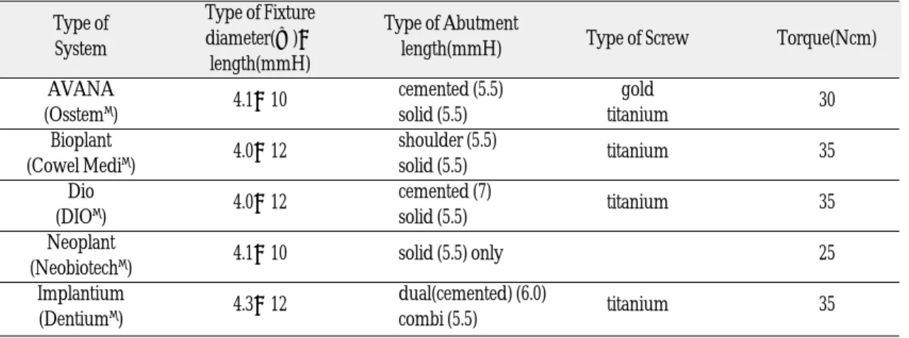
The implant fixtures selected in this study were internal connection type implants from AVANA Standrad fixture(�4.1×10 mmH; Osstem�), Bioplant Standard fixture(�4.0×12 mmH; Cowell Medi�), Dio Standard fixture(�4.0×12 mmH;
DIO�), Neoplant Standard fixture(�4.1×10 mmH; Neobiotech�), Implantium Standard fix- ture(�4.3×12 mmH; Dentium�). All fixture made by Korean manufactures. The fixtures were chosen at random, each group was acquired 2 fixtures. Total 20 implant fixtures of 5 implant system were selected.
2) Abutment
Two piece(cemented) type abutment and one piece(solid) type abutment for use with each implant system were acquired. The abutments were regarded as a standard type and selected with the manufacture recommendations. Respectively AVANA cemented abutment(4.8×5.5 mmH), AVANA solid abument(5.5 mmH), Bioplant Shoulder (cemented) abutment(5.5 mmH), Bioplant solid abutment(5.5 mmH), Dio cemented abut- ment(4.8×7 mmH), Dio solid abutment(5.5 mmH), Implantium dual(cemented) abutment(6.0), Implantium combi(solid) abutment(6.0×5.5 mmH), Neoplant solid abutment(5.5 mmH) were selected. Especially, Neoplant system had only a solid abutment. The abutments were chosen at ran- dom, each group was acquired 2 abutments.
3) Screw
Screw were respectively used to hold a two piece type abutment to a implant fixture. AVANA system had gold alloy screw and titanium screw.
Other systems had only titanium screw. But Noeplant system didn’t have any screw because this system had only one piece type abutment.
Table I. Kinds of implant system in this study Type of Type of Fixture
Type of Abutment
System diameter(�)×
length(mmH) Type of Screw Torque(Ncm)
length(mmH) AVANA
4.1×10 cemented (5.5) gold
(Osstem�) solid (5.5) titanium 30
Bioplant
4.0×12 shoulder (5.5)
titanium 35
(Cowel Medi�) solid (5.5)
Dio 4.0×12 cemented (7)
titanium 35
(DIO�) solid (5.5)
Neoplant
4.1×10 solid (5.5) only 25
(Neobiotech�) Implantium
4.3×12 dual(cemented) (6.0)
titanium 35
(Dentium�) combi (5.5)
2. Methods
1) Implant fixture mounting in resin block The implant fixtures were perpendiculary mounted in polymethyl methacrylate autopoly- merizing acrylic resin block(Orthodontic resin, Densply international Inc. USA)
2) Connection of each abutment to implant Each two piece abutment was secured to the implant fixture by screw and one piece abut- ment also secured to the implant fixture with recommended torque value using manufacture's recommended torque controller(Fig. 1). The abut- ment screw and one piece type abutment were retightened after 24 hours.
3) Abutment/fixture assembly mounting in polyester
Abutment/fixture assembly were mounted in liquid unsaturated polyester. Each one was embedded completely. The mounting media (Epovia, Cray Valley Inc.) was a 2-part system made up of a resin base and activator. The two components were mixed together and poured and allowed to cure completely during overnight.
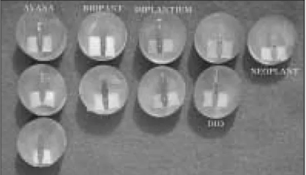
4) Cross section and polishing of all samples All samples were cross sectioned with grinder- polisher unit(OMNILAP 2000 SBT Inc)(Fig. 2, 3). The initial grinding was performed with 200 grit silicon carbide paper. Polishing was contin- ued with 600, 1000, 1200 grid silicone carbide paper. All specimens were cleaned with a liquid soap and water in an ultrasonic cleaner during 10 minutes. Finally, all specimens were steam-spray cleaned by Aquaclean3 (Degussa Dental) and dried carefully.
5) Analysis of fit between implant fixture/abut- ment/screw interfaces
Optical microscope(Steroscopic Zoom Micros- cope, Germany, Zeiss Inc, Model:SV-11) and FE- SEM(field emission scanning electron micro- scope, Netherland, Phillips co., Medel: XL 30 SFEG) were used to evaluate fit of all samples.
Fig. 1.Torque devices
Fig. 2.Grinder polisher unit (OMNILAP 2000 SBT Inc)
Fig. 3. Specimens which were cross-sectioned and polished
RESULTS
The Fit of AVANA System (Fig. 4, 5, 6)
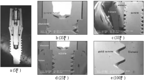
1. The fit between the implant fixture/abut- ment/screw interfaces in the AVANA-1 piece system (Fig. 4)
1) The fit between the implant fixture/abutment interface(Fig. 4-a,b)
The interface showed very close and broad surface contact. approximately, all abut- ment surface was contacted with internal wall of fixture.
2) The fit between the screw/implant fixture interface(Fig. 4-a,c,d)
The interface showed upper surface con- tact but that was not close. Large gap remained at lower part of the root terminal.
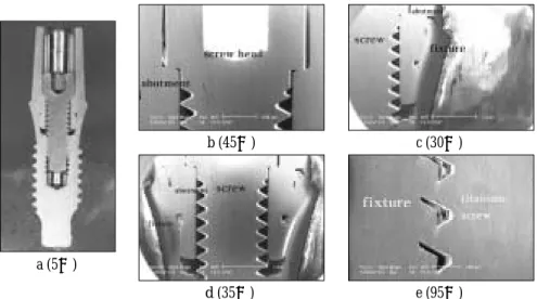
2. The fit between the implant fixture/abut- ment/screw interfaces in the AVANA-2 piece, gold screw-system (Fig. 5)
1) The fit between the abutment/screw inter- face(Fig. 5-a,b,c,d)
The interface showed close contact at the low- er part of screw head. But variable gap existed except this area.
2) The fit between the implant fixture/abutment interface(Fig. 5-a,c,d)
The upper half surface showed close contact.
But variable gap existed except this area.
3) The fit between the screw/implant fixture interface(Fig. 5-e)
The interface showed uniform close con- tact at upper side and fair state.
3. The fit between the implant fixture/abut- ment/screw interfaces in the AVANA-2 piece type, titanium screw-system (Fig. 6)
1) The fit between the abutment/screw inter- face(Fig. 6-a,b,c,d)
The interface showed close contact at the low- er part of screw head. But variable gap existed except this area.
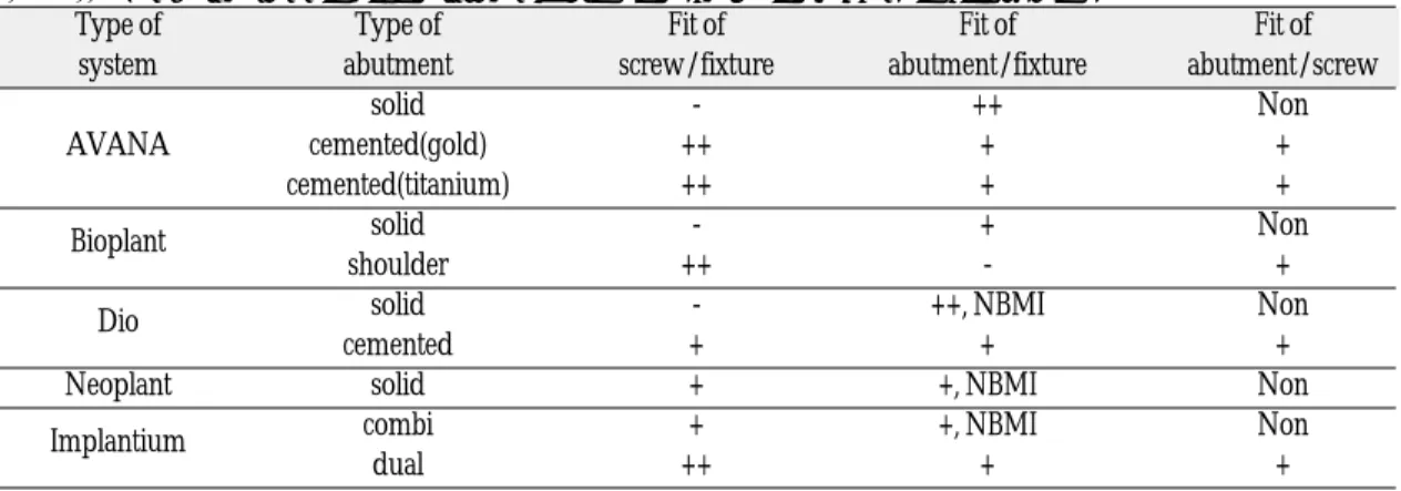
Table II. The Fit of the implant fixture/abutment/screw interfaces in all systems.
Type of Type of Fit of Fit of Fit of
system abutment screw/fixture abutment/fixture abutment/screw
solid - ++ Non
AVANA cemented(gold) ++ + +
cemented(titanium) ++ + +
Bioplant solid - + Non
shoulder ++ - +
Dio solid - ++, NBMI Non
cemented + + +
Neoplant solid + +, NBMI Non
Implantium combi + +, NBMI Non
dual ++ + +
Note
Non ; Not exited
NBMI ; Not Bilateral Mirror Image ++ ; very closed or good condition + ; To 50% closed or fair condition - ; not closed or bad condition
2) The fit between the implant fixture/abutment interface(Fig. 6-a,c,d)
The upper half surface showed close contact.
But variable gap existed except this area.
3) The fit between the screw/implant fixture interface(Fig. 6-e)
The interface showed uniform close con- tact at upper side and fair state.
4) As compared with a gold screw, the interface of the titanium screw was similar to that
of the gold screw under recommended torque.
The Fit of Bioplant System (Fig. 7, 8)
1. The fit between the implant fixture/abut- ment/screw interfaces in the Bioplant-1 piece- system (Fig. 7)
1) The fit between the implant fixture/abutment interface(Fig. 7-a,b)
Fig. 4. Optical cross-section micrograph (a) and SEM (b,c,d) of joint connection in AVANA(1 piece) implant system.
b (32×)
a (5×) c (45×) d (100×)
Fig. 5. Optical cross-section micrograph (a) and SEM (b, c, d, e) of joint connection in AVANA (2 piece-gold screw) implant system.
b (35×)
a (5×)
c (35×)
d (25×) e (100×)
The interface showed close contact at upper third and lower narrow area. Variable gap was existed. Approximately, 50%-surface contact existed.
2) The fit between the screw/implant fixture interface(Fig. 7-a,c,d)
The interface showed superior surface con- tact which was not close. Large gap remained at lower part of the root terminal.
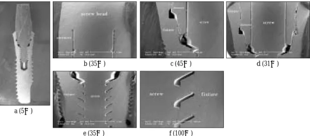
2. The fit between the implant fixture/abut- ment/screw interfaces in the Bioplant-2 piece- system (Fig. 8)
The Bioplant internal 2 piece type had a unique design compared with other systems in this study.
1) The fit between the abutment/screw inter- face(Fig. 8-a,b,c,d)
The interface showed close contact at low- er part of screw head. But variable gap Fig. 7. Optical cross-section micrograph (a) and SEM (b,c,d) of joint connection in Bioplant(1 piece) implant system.
b (30×)
a (5×) c (35×) d (100×)
Fig. 6. Optical cross-section micrograph (a) and SEM (b, c, d, e) of joint connection in AVANA (2 piece-titanium screw) implant system.
b (45×)
a (5×)
c (30×)
d (35×) e (95×)
existed except this area.
2) The fit between the implant fixture/abutment interface(Fig. 8-a,c,d)
Variable gap was existed in joint interface.
The state of interface was not fair.
3) The fit between the screw/implant fixture interface(Fig. 8-e,f)
The interface showed uniform close con- tact at upper side and fair state.
The Fit of Dio System (Fig. 9, 10)
1. The fit between the implant fixture/abut- ment/screw interfaces in the Dio implant-1 piece-system (Fig. 9)
1) The fit between the implant fixture/abutment interface(Fig. 9-a,b,c)
The interface showed very close and broad surface contact. Approximately, all abut-
Fig. 8. Optical cross-section micrograph (a) and SEM (b, c, d e, f) of joint connection in Bioplant (2 piece) implant system.
b (35×)
a (5×)
c (45×)
e (35×) f (100×)
d (31×)
Fig. 9. Optical cross-section micrograph (a) and SEM (b, c, d, e) of joint connection in Dio (1 piece) implant system.
b (32×)
a (5×)
c (35×)
d (50×) e (100×)
ment surface was contact with internal wall of fixture.
2) The fit between the screw/implant fixture interface(Fig. 9-a,d,e)
The interface showed at upper surface con- tact which was not close. Large gap remained at lower part of the root terminal.
3) Bilateral gap at lower joint interface was not equal.(Fig. 9-a,c)
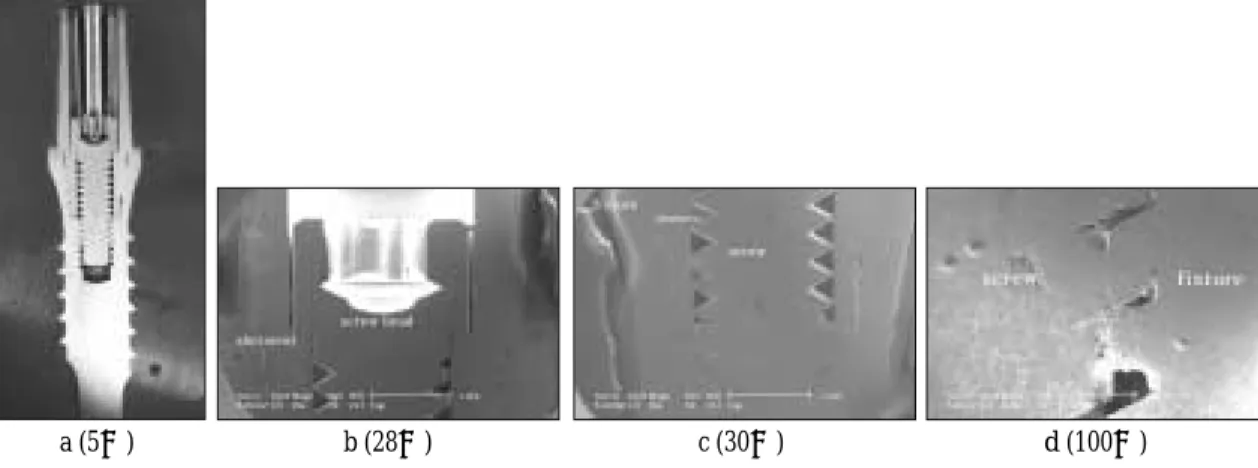
2. The fit between implant the fixture/abut- ment/screw interfaces in the Dio implant-2 piece-system (Fig. 10)
1) The fit between the abutment/screw inter- face(Fig. 10-a,b,c)
The interface showed close contact at low- er part of screw head. And remained area showed fair joint interface.
2) The fit between the implant fixture/abutment interface(Fig. 10-a,c)
The interface showed small gap and joint interface was fair.
3) The fit between the screw/implant fixture interface(Fig. 10-a,c,d)
The interface showed uniform close con- tact at upper side and fair state.
The Fit of Neoplant System (Fig. 11)
1. The fit between the implant fixture/abut- ment/screw interfaces in the Neoplant-1 piece- system (Fig. 11)
Neoplant system had only 1 piece type abut- ment.
1) The fit between the implant fixture/abutment interface(Fig. 11-a,b,c)
The interface showed close contact at upper third and lower narrow area. approximately, 50%-surface contact existed.
2) The fit between the screw/implant fixture interface(Fig. 11-a,c,d)
The interface showed uniform close con- tact at upper side and fair stat. Large gap remained at lower part of the root terminal.
3) Bilateral gap at middle abutment joint inter- face was not equal.(Fig. 11-a,b)
The Fit of Implantium System (Fig. 12,13)
1. The fit between the implant fixture/abut- ment/screw interfaces in the Implantium-1 piece-system (Fig. 12)
1) The fit between the implant fixture/abutment
Fig. 10. Optical cross-section micrograph (a) and SEM (b, c, d) of joint connection in Dio (2 piece) implant system.
b (28×)
a (5×) c (30×) d (100×)
interface(Fig. 12-a,b)
The interface showed very close and good surface contact. And smallest gap existed compared with other systems in this study.
2) The fit between the screw/implant fixture interface(Fig. 12-c,d)
The interface showed uniform close con- tact at upper side and fair state.
3) Bilateral gap at middle abutment joint inter- face was not equal.(Fig. 12-a,b)
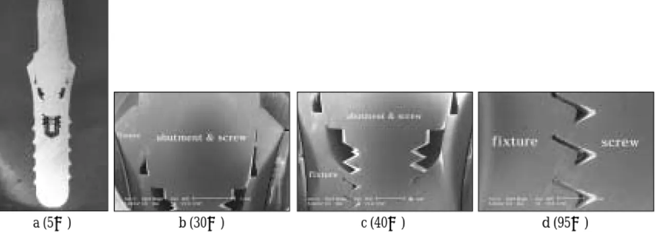
2. The fit between the implant fixture/abut- ment/screw interfaces in the Implantium-2 piece-system (Fig. 13)
1) The fit between the abutment/screw inter- face(Fig. 13-a,b,c)
The interface showed good fit.
2) The fit between the implant fixture/abutment interface(Fig. 13-c,d)
The interface showed good condition at upper and lower third. And small gap exist- ed at middle third.
Fig. 12. Optical cross-section micrograph (a) and SEM (b, c, d) of joint connection in Implantium (1 piece) implant system.
b (30×)
a (5×) c (40×) d (100×)
Fig. 11. Optical cross-section micrograph (a) and SEM (b, c, d) of joint connection in Neoplant (1 piece) implant system.
b (30×)
a (5×) c (40×) d (95×)
3) The fit between the screw/implant fixture interface(Fig. 13-d,e)
The interface showed uniform close con- tact at upper side and fair state.
DISCUSSION
In internal connection of home-made implant sys- tems, the component joint interfaces were in good condition. And the results of the above study showed that materials and mechanical properties and quality of milling differed depend- ing on their manufacturing companies. Binon3 reported that while the products by each manu- factured company had a good degree of precision and accuracy, each system was revealed a system's difference between them in accuracy of inter- components.
The Fit of the abutment/screw interface The abutment/screw interfaces existed in two piece type connection. Joint connection state in all systems was in good condition at lower border of
screw head. But variable gap exited in another area except this area. Persson et, al.15reported that presence of bacteria was the result in a contam- ination of the fixture and abutment components during the 1st and/or 2nd stage of implant instal- lation, a transmission of microorganisms from the oral environment during function subsequent to bridge installation. Ericsson et, al.16reported that the colonization of bacteria inside the implant sys- tem and the penetration of bacteria or their prod- ucts via the microgap-between the fixture and the abutment-might constitute a risk for soft tissue inflammation and loss of supporting bone. Like this reason, despite the fact that the microgap inevitably exists in all system, it is better to strive to reduce the possibility of having microgap.
The Fit of the abutment/implant fixture inter- face
In this study, Only Implantium system had 11 degree morse taper and other systems had 8 degree morse taper. Sutter et, al.14proposed an 8 degree taper connection, referred to in the liter- Fig. 13. Optical cross-section micrograph (a) and SEM (b, c, d, e) of joint connection in
Implantium (2 piece) implant system.
b (32×)
a (5×)
c (35×)
d (50×) e (100×)
ature as the ITI Morse taper, between implant and abutment as an optimal combination of pre- dictable vertical positioning and self locking characteristics.
Generally, two piece type connection was supe- rior to one piece type connection in this study.
Because fixtures of all systems were synOcta implant fixture. SynOcta fixture had index at implant level and positioning notch for pros- thetic convenience. Although one piece type abutment also used this fixture. Two piece type abutment was developed privite use at synOcta fixture. So joint interface between this fixture and original one piece abutment had reduced total joint interface to 31 % compared with that between original one piece abutment and origi- nal fixture. Squier et, al.13reported that reduced connected surface didn’t have an influence on screw joint stability. This reduction was that one piece abutment was partially connection with inner surface of synOcta fixture. For this rea- son, Dio, Implantium, Neoplant system didn’t have bilateral mirror image in geometric condi- tion. If original fixture used in this study, the result had reverse effects. Among the products of several companies, Especially AVANA, Dio, Implantium systems had broad and very close con- nection in one piece type joint interface.
The Fit of the implant fixture/screw interface Generally, two piece type connection was supe- rior to one piece type connection. This reason is that one piece type connection gains joint stabil- ity from friction force at morse taper and preload by screw. Most of this stability is gained friction force at morse taper. Preload by screw doesn’t mainly take part in joint stability. But in two piece connection, most of joint stability is gained from the preload by screw, when it is connect- ed.10-14,17,18For this reason, if one piece system is acquired the more accuracy at lower screw/fix-
ture joint interface, the more stability is gained.
Although two piece type was superior to one piece type, Neoplant and Implantium system showed good quality at lower part of the screw/fix- ture interface.
In the process of making test specimens, the loss of preload or loss of integrity between components might occur. The joints of the structural com- ponents might be loosened due to a loss of the pre- load during procedure of the grinder-polisher. This phenomenon, which had been observed in a few experiments, was confirmed to be a failure of specimens. This was more obvious in a lower grid carbide paper, but this was lesser observed in the higher grid carbide paper.
The loss of preload might also occur during the ultrasonic cleaning process aimed for probation of the structural joints. This loss had occurred in some test specimens and it was considered that the longer the cleaning was the higher the rate of loss was. In order to minimize the occurrence of the above these errors, grind-polisher was care- fully used throughout multi grid levels, and The procedure of ultrasonic cleaning was shortened and the steam-spray was used for long time.
In addition, the specimens were probed with a optical scanning microscope. The test specimens used in the experiment were only those that had been found in good condition in the implant fix- ture/abutment joint patterns in case of the one piece types which had invariably a sensitive joint area, and the screw/fixture joint patterns in case of the two piece types. However, it was dif- ficult to conclude that the above potential prob- lems were completely avoided in an experiment.
This experiment was a pre-test for the accept- ability assessment of home-made internal implant system after and under the load. The above errors may act as a big obstacle to alter the pre-set preload of the specimen during the process of mak- ing specimens, thereby seriously effecting the
conclusion of such an experiment.
Therefore, in a future additional experiment, the development of a different method of making test specimens is needed.
CONCLUSIONS
The data obtained from the implant fixture/abut- ment/screw interfaces using Stereoscopic Zoom microscope and FE-SEM supported the following conclusions:
1. Implant fixture/abutment/screw connection interfaces of internal connection systems made in Korea were in good condition.
1) The abutment/screw interface was that joint connection in all systems were in good condition at lower border of the screw head.
2) The abutment/fixture interface was that generally, two piece type connection was superior to one piece type connection in this study.
3) The screw/fixture interface was that gen- erally, two piece type connection was supe- rior to one piece type connection in this study.
2. The results of the above study showed that materials and mechanical properties and qual- ity of milling differed depending on their manufacturing companies.
Conclusively although mechanical geometry was different, each system showed good con- nection interfaces. But it was difficult to come to a conclusion from these facts. Because the spec- imens of each type were just two and it was inevitable to have potential errors in experiment.
Although joint interfaces were in good condi- tion in this study, more study related to load distribution in contact interfaces and change of joint stability and fit by long term load is needed.
REFERENCES
1. Bynre D, Houston F, Cleary R, Claffey N. The fit of cast and premachined implant abutments. J Prosthet Dent 1998;80:184-92.
2. Binon P. Evaluation of maching Accuracy and Consistency of Selected Implant, Standard Abutments and Laboratory Analog. Int J Prosthodont 1995;8:162-78.
3. Binon P. Implants and components :Entering the new millennium. Int J Oral Maxillofac Implants 2000;5:76-94.
4. Sones AD. Complication with osseointegrated implants. J Prosthet Dent 1989;62:81-585.
5. Sakaguchi RL, Borgersen SE. Nonlinear finite el- ement contact analysis of dental implant compo- nents. Int J Oral Maxillofac Implants 1993;8:655-61.
6. Boggan R, Strong J, Misch C. Influence of hex geometry and prosthetic table width on static and fatigue strength of dental implants. J Prosthet Dent 1999;82:436-40.
7. Quirynen M, Bollen CML, Eyssen H, Van Steenberghe D. Microvial penetration along the im- plant components of the Branemark system. An in vitro study. Clin Oral Implants Res 1994;5:239- 44.
8. Besimo CE, Guindy JS, Lewetag D, Meyer J.
Prevention of bacterial leakage into and from pre- fabricated screw-retained crown on implants in vit- ro. Int J Oral Maxillofac Implants 1999;14:654-60.
9. Gross M, Abramovich I, Weiss EI. Microleakage at the abutment implant interface of osseointergrat- ed implants. Int J Oral Maxiollfac Implants 1999;14:94-100.
10. Beat R. Mechanics of the implant-abutment con- nection: An 8-degree taper compared to a butt joint connection. Int J Oral Maxillofac Implants 2000;15:519-26.
11. Norton MR. An in vitro evaluation of the strength of an internal conical interface compared to a butt joint interface in implant design. Clin Oral Implants Res 1997;8:290-8.
12. Norton MR. An in vitro evaluation of the strength of a 1-piece and 2-piece conical abutment joint in implant design. Clin Oral Implants Res 2000;11:458-64.
13. Squier RS, Psoter WJ, Taylor TD. Removable torques of conical, tapered implant abutments:
the effects of anodization and reduction of surface area. Int J Oral Maxillofac Implants 2002;17:24-7.
14. Sutter F, Weber HP, Sorensen J, Belser U. The new restorative concept of the ITI dental implant system: design and engineering. Int J Periodontics
& Restorative Dentistry 1993;13:409-31.
15. Persson LG. Bacterial colonization on internal surfaces of Branemark system implant compo- nents. Clin Oral Implants Res 1996;7:90-5.
16. Ericsson I, Persson LG, Berglundh T, Marinello CP, Lindhe J, Klinge B. Different types of inflammatory reactions in periimplant soft tissues. J Clin Periodont 1995;22:255-61.
17. Merz BR, Hunenbart S, Belser UC. Mechanics of the implant connection: an 8-degree taper compared to a butt joint connection. Int J Oral Maxillofac Implants 2000;15:519-26.
18. Schulte J, Coffey J. Comparison of screw retention of nine abutment systems: A pilot study. Implant Dent 1997;6:28-31.
19. Akca K, Cehreli MC, Iplikcioglu H. Evaluation of the mechanical characteristics of the implant abut- ment complex of a reduced diameter morse taper implant; a non-linear finite element stress analy- sis. Clinical Oral Implants Research 2003;14:444-55.
20. Behneke A, Behneke N, d’Hoedt B. The longitu- dinal clincal effectiveness of ITI solid screw implants in partially edenturous patients: a 5-year follow up report. Int J Oral Maxillofac Implants 2000;15:633- 45.
21. Binon P, Brunski P, Gulbransen H. The role of screws in implant systems. Int J Oral Maxillofac Implants 1994;9:48-62.
22. Binon P, McHugh M. The effect of eliminating implant/abutment rotational misfit on screw joint stability. Int J Prosthodont 1996;9:511-9.
23. Breeding L, Dixon D. Torque required to loosen sin- gle-tooth implant abutment screws before and after simulated function. Int J Prosthodont 1993;6:435-9.
24. Brunski JE, Hipp JE. In the forces on endosteal im- plant; A mesurement system and biomechanical con- sideration. J Prosthet Dent 1984;51:82-90.
25. Burguette RL, Johns MR, King TB, Patterson EA.
Tightening characteristic for screwed joint in os- seointergrated dental implant. J Prosthet Dent 1994;71:592-9.
26. Carr AB, Brunski JB, Hurley E. The effect of finishing and polishing techniques in implant cylinder pre- load; 9th Annual Meeting of the Academy of Osseointergration(Abstract). Int J Oral Maxiollfac Implants 1995;10:123-4.
27. Charles JG, Joseph YKK, Kitichai R. Clinical com- plications of osseintegrated implants. J Prosthet Dent 1999;81:537-52.
28. Cibirka R, Nelson S. Examination of the im- plantabutment interface after fatigue testing. J Prosthet Dent 2001;85:268-75.
29. Dixon D, Breeding L, Sadler P, Mckay M.
Comparison of screw loosening, rotation, and de- flection among three implant designs. J Prosthet Dent 1995;74:270-8.
30. Ekfeldt A. Clinical evaluation of single-tooth restorations supported by osseointergrated im-
plants: A retrospective study. Int J Oral Maxiollfac Implants 1994;9:179-83.
31. Haack JE, Sakaguchi RL, Sun T, Coffey JP.
Elongation and preload stress in dental implant abutment screws. Int J Oral Maxillofac Implants 1995;10:529-36.
32. Jeong YT, Chung CH, Lee HT. Screw joint stabil- ity according to abutment screw materials. J Korean Acad prosthodont 2002;40:275-86.
33. John K. Schulte, James Coffey. Comparison of screw retention of nine abutment systems:A pilot study. Implnat Dent. 1997;6:28-31.
34. Kim NH, Chung CH, Son MK, Back DH. A study on the fit of the implant-abutment-screw interface.
J Korean Acad Prosthodont 2003;41:503-18.
35. Khraisat A, Stegaroiu R, Nomura S, Miyaka WO.
Fatigue resistance of two implant/abutment joint designs. J Prosthet Dent 2002;88:604-10.
36. Laney W, Jemt T, Harris D. Osseointegrated im- plants for single-tooth replacement: Progress report from a multicenter prospective study after 3years.
Int J Oral Maxillofac Implants 1994;9:49-54.
37. Levine RA, et al. A multicenture retrospective analysis of ITI implant system used for single- tooth replacement: Preliminary results at six or more months of loading. Int J Oral Maxillofac Implants 1997;12:237-42.
38. Martin WC, Woody RD, Miller BM, Miller AW.
Implant abutment screw rotations and preloads for four different screw materials and surfaces. J Prosthet Dent 2001;86:24-32.
39. McGlumphy E, Holloway J. Implant screw me- chanics. Dental clinic of north America 1998;42:71- 89.
40. Norton MR. Assessment of cold welding proper- ties of internal conical interface two commercial- ly available implant system. J Prosthet Dent 1999;81:159-66.
41. Norton MR. In vitro evaluation of the strength of the conical implant-to-abutment joint in two com- mercially available implant systems. J Prosthet Dent 2000;83:567-71.
42. Rangert B, Langer B. Bending overload and implant fracture: a retrospective clinical analysis. Int J Oral Maxillofac Implants 1995;10:326-34.
43. Schwrz MS. Mechanical complications of dental im- plants. Clinical Oral Implants Res 2000;1:156-8.
Reprint request to:
CHAE-HEONCHUNG D.D.S., M.S.D., Ph.D.
DEPARTMENT OF PROSTHODONTICS,COLLEGE OFDENTISTRY, CHOSUNUNIVERSITY,
421, SEOSUK-DONG,DONG-GU, GWANGJU, 501-825, KOREA [email protected]