1. INTRODUCTION
Recently, research on Intelligent Transportation System (ITS) and autonomous driving technologies are being actively performed all over the world. ITS refers to a system that combines artificial intelligence to traditional transportation systems to provide information and is controlled according to the circumstances to provide convenience to the users. The next-generation ITS requires a positioning performance that can distinguish lanes to provide advanced services, which is being researched and developed through satellite navigation
Performance Analysis of GPS/BDS Integrated Precise Positioning System Considering Visibility in Urban Environments
Jae Hee Noh
1, Sun Yong Lee
2, Deok Won Lim
3, Sang Jeong Lee
1†1
Department of Electronics Engineering, Chungnam National University, Daejeon 34134, Korea
2
Navcours Co., Ltd., Daejeon 34014, Korea
3
Satellite Navigation Team, Korea Aerospace Research Institute, Daejeon 34133, Korea
ABSTRACT
In recent years, Intelligent Transport Systems (ITS) and Autonomous Vehicle Technology have actively studied around the world. In order to achieve the purpose of Advanced Driver Assistance System (ADAS) and Autonomous Vehicle Technology, it must be obtained accurate and reliable positioning. However, the problem of positioning in the urban area is a low position accuracy caused by the reduction of the number of visible satellites due to high buildings. In this paper, we analyzed the availability of precise positioning system in urban area are using GPS/BDS integrated system. For this study, GPS and BDS satellite signals were collected using two low-cost receivers in the open sky and a designed software based platform for precise positioning performance analysis. And we analyzed the precise positioning performance by changing the mask angle considering the urban area. From the results, it can be confirmed that the performance of precise positioning of GPS only and BDS only decrease in the environment where mask angle is 40° to 45°, however, GPS/BDS integrated system maintains high performance of precise positioning.
Keywords: ITS, GPS, BDS, precise positioning, urban
positioning technologies. In order to achieve the objectives of ITS and autonomous driving technologies, precise control is required as well as accurate and reliable vehicle position information (Kang et al. 2013). Currently, land transportation requires a position accuracy of less than 50 cm (2DRMS), which is the level of distinguishing lanes, so research on precise positioning is being actively carried out to provide accurate position data for land transport at home and abroad (Son et al. 2013). However, the most significant problem when performing accurate positioning in urban canyon is the degradation of positioning performance due to the lack of visible satellites.
Studies on precise positioning using multiple satellite navigation systems are necessary because it is difficult to secure enough visible satellites when performing precise positioning using a single navigation system in urban canyon. Prior to the open service of BDS, most of the studies on positioning were focused on using GPS/GLONASS for navigation. However, GLONASS uses Frequency Division Received Oct 11, 2018 Revised Dec 22, 2018 Accepted Dec 27, 2018
†
Corresponding Author E-mail: [email protected]
Tel: +82-42-825-3991 Fax: +82-42-823-5436
Jae Hee Noh https://orcid.org/0000-0002-6314-738X
Sun Yong Lee https://orcid.org/0000-0003-4278-4109
Deok Won Lim https://orcid.org/0000-0002-5154-8063
Sang Jeon Lee https://orcid.org/0000-0002-9400-5157
or mitigate the ICB because it is difficult to determine the ICB by a simple frequency ratio since the carrier phase measurement ICB magnified from the frequency number exceeds the length of one wavelength (Wanninger &
Wallstab-Freitag 2007, Yamada et al. 2010). In addition to the ICB problem, in terms of GLONASS measurements in the double-differentiated measurement model, the ambiguity is estimated as a real number rather than an integer (Pratt et al.
1997). On the contrary, BDS adopts the same CDMA method as GPS and provides the parameters necessary for calculating the satellite positions, which makes it easier to implement multiple satellite navigation systems than GLONASS. Since BDS began open service, positioning studies using GPS/BDS have been actively performed in the Asia-Pacific region as it became possible to secure enough available BDS satellites (Teunissen et al. 2014, Zhao et al. 2014, Chen et al. 2016).
In order to analyze the availability of precise positioning using BDS in urban areas, this study analyzed the precise positioning performance of GPS-only, BDS-only, and an integrated GPS/BDS system while increasing the mask angle.
For this purpose, Chapter 2 examines the operational status and characteristics of BDS and describes the integrated GPS/
BDS precise positioning technique. In Chapter 3, we analyzed the precise positioning results while changing the mask angle in order to analyze the change in availability due to the limited number of visible satellites in urban environments.
As a result, we confirmed that using an integrated GPS/BDS system in high mask angles improves the precise positioning availability and accuracy.
2. GPS/BDS PRECISE POSITIONING
2.1 BDS Operation Status & Signal Structure
BDS is a satellite navigation system developed and operated by China, which consists of 3 development stages.
In phase 1, 3 geostationary orbit (GEO) satellites were used to provide services in the area of 70°E - 140°E longitude and 5°N - 55°N latitude. The next phase, Beidou-2, is a regional satellite navigation system consisting of 35 satellites, which is currently being developed to improve
the position accuracy. Beidou-2 satellites consist of GEO satellites, medium earth orbit (MEO) satellites, and incline geosynchronous orbit (IGSO) satellites. A total of 15 satellites are currently in operation to provide services in the Asia-Pacific region. Table 1 summarizes the BDS satellites currently in operation. The position accuracy of areas with Beidou-2 service was optimized from 10 m to 6 m. Beidou-3, the final stage of development, is currently under research and development with the goal of providing services across the globe by operating 35 satellites by 2020 (Lu 2018, International GNSS Service 2018).
Beidou-2 satellites provide B1, B2, and B3 signals, with respective carrier frequencies of 1561.098 MHz, 1207.140 MHz, and 1269.520 MHz. All 3 signals use I and Q channels, in which I channel signals are for public service for civilian use while Q channel signals are for military use. The Interface Control Document (ICD) for B1I and B2I signals were released in 2012 and the ICD for B3I signals will be released in 2018 for public use. Beidou-3 satellites will provide a total of 5 signals, including B1C, B2a, and B2b signals as well as B1I and B3I signals. Currently, the ICD beta version for B1C and B2a has been released (Lu 2018, European Space Agency 2018). Fig. 1 shows the allocation of BDS frequencies up to date.
2.2 GPS/BDS Precise Positioning Technique
Precise positioning is a relative positioning technique that uses both code measurements and carrier phase measurements. In terms of using only code measurements, an accuracy of up to several meters can be obtained, whereas using carrier phase measurements allows precise position estimations with an accuracy of several centimeters. The double differenced code measurements and carrier phase measurements for each system can be expressed as in Eqs.
8 9 10 11 12 13 14 15
Beidou IGSO5 Beidou G5 Beidou M3 Beidou M4 Beidou M6 Beidou G6 Beidou IGSO6
Beidou G7
C10 C05 C11 C12 C14 C02 C13 C17
IGSO
GEO
MEO
MEO
MEO
GEO
IGSO
GEO
(1-4). The double differenced GPS code measurement:
, , ( ),
ij ij ij
ur GPS ur GPS P GPS ur
P ρ ε
∇∆ = ∇∆ + ∇∆ (1)
where ε
p(GPS),uris the measurement noise, ρ is the geometric distance between the satellite and the receiver. u and r refer to the user and reference station reception, respectively, and i and j are the i-th and j-th satellites, respectively. The double differenced BDS code measurement:
, , ( ),
ij ij ij
ur BDS ur BDS P BDS ur
P ρ ε
∇∆ = ∇∆ + ∇∆ (2)
where ε
p(BDS),uris the measurement noise in the BDS code measurement. The double differenced GPS carrier phase measurement:
(3)
where ε
ϕ(GPS),uris the measurement noise in the GPS carrier phase measurement, λ is the length of one wavelength of GPS L1 signal carrier phase measurement, and N refers to the integer ambiguity in the GPS carrier phase measurement.
The double differenced BDS carrier phase measurement:
(4) where ε
ϕ(BDS),uris the measurement noise in the BDS carrier phase measurement, λ is the length of one wavelength of BDS B1 signal carrier phase measurement, and N refers to the integer ambiguity in the BDS carrier phase measurement (Teunissen & Montenbruck 2017).
The conceptual structure that linearizes the double difference measurements in the Short-baseline can be defined as in Eq. (5).
PR
0
PRCP CP
y B b
y y B A a
ε ε
= = +
(5)
where y is defined as y = [y
1,PRy
2,PR… y
n,PRy
1,CPy
2,CP… y
n,CP]
T, PR is the code measurement, and CP is the carrier phase measurement. b is a 3-dimensional position vector, a is a double difference integer ambiguity vector, and B and A represent coefficient matrices of b and a, respectively. Eq. (6) is the result of expressing the linearized double difference observation equation for one satellite system in Eq. (5) for the integrated GPS/BDS system.
, , , ,
( ) 0 0
( ) 0
( ) 0 0
( ) 0
GPS PR GPS
GPS CP
GPS GPS
GPS BDS PR
BDS BDS
BDS CP
BDS BDS
B t B t A b
y a
B t a
B t A
ε ε ε ε
= +
(6)
When GPS and BDS are integrated, the 3-dimensional position vector includes both the GPS and BDS clock error terms, which can be expressed as in Eq. (7). Where δt
GPSis the GPS receiver clock error term and δt
BDSis the BDS receiver clock error term.
[
GPS BDS]
b= x y z δt δt
(7)
Using the measurement residual y calculated from the linearized equation, the position is estimated by the weighted least squares method at each point. The weighted least squares method equation can be defined as in Eq. (8).
( )
1ˆ T T
x= H WH −H W y⋅
(8)
where W represents a weight matrix consisting of
covariances, the weighted least squares method calculates
with higher weights as the accuracy of the measurements
is higher, which leads to more precise position estimations
than the least squares method (Teunissen & Montenbruck
2017). The integer ambiguity ǎ is calculated by using the
integer ambiguity â, position solution b̂, and the respective
covariance matrices Q
âand Q
b̂, obtained by applying the least
Fig. 1. The frequency bands of BDS.
solution and float solution, respectively, and ǎ â are the integer ambiguity components of the integer solution and float solution, respectively. Q
b̂âis the covariance matrix for the base component of the float solution and the integer ambiguity component. The float ambiguity â is converted into a new integer ambiguity ẑ by using the Z matrix to convert the covariance matrix Q
âinto a new covariance matrix (de Jonge & Tiberius 1996, de Jonge et al. 1996). The conversion equation:
ˆ
ˆ T
z a
Q =Z Q Z
(10)
where the Z matrix is a matrix that converts the integer ambiguity space, in which a 1:1 integer conversion relationship holds, and all elements of the Z matrix should be integers and the determinant should be 1. The integer ambiguity ǎ is a value that minimizes the conditions in Eq.
(11), and the integer ambiguity search that minimizes the search conditions in Eq. (11) is performed on the grid points in an ellipse consisting of n-dimensional integer ambiguities defined from the variance-covariance matrix of integer ambiguities.
ˆ1
ˆ 2
mina a a− Qa− with a Z∈ n
(11)
Once the integer ambiguity is resolved in the area converted to Z, the original integer ambiguity is calculated through Eq. (12) and the integer solution is estimated through Eq. (10) (de Jonge & Tiberius 1996, de Jonge et al. 1996).
( )
T 1a= Z − z
(12)
3. AVAILABILITY ANALYSIS IN AN URBAN ENVIRONMENT
3.1 Experimental Configuration
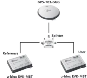
In order to analyze the precise positioning performance for GPS-only, BDS-only, and the integrated GPS/ DS system, this study established a zero-baseline environment in an open area to collect signals and design a platform to analyze
the precise positioning performance. Fig. 2 shows the environment for collecting signals, in which GPS L1 and BDS B1 signals were collected for 24 hours (September 8, 2018, 21:30 (UTC+09:00) - September 9, 2018, 21:30 (UTC+09:00)) using NovAtel GPS-703-GGG antennas and 2 u-blox EVK- M8T. The signals were acquired in an open area, and the location of the receiver was 36.364° longitude and 127.345°
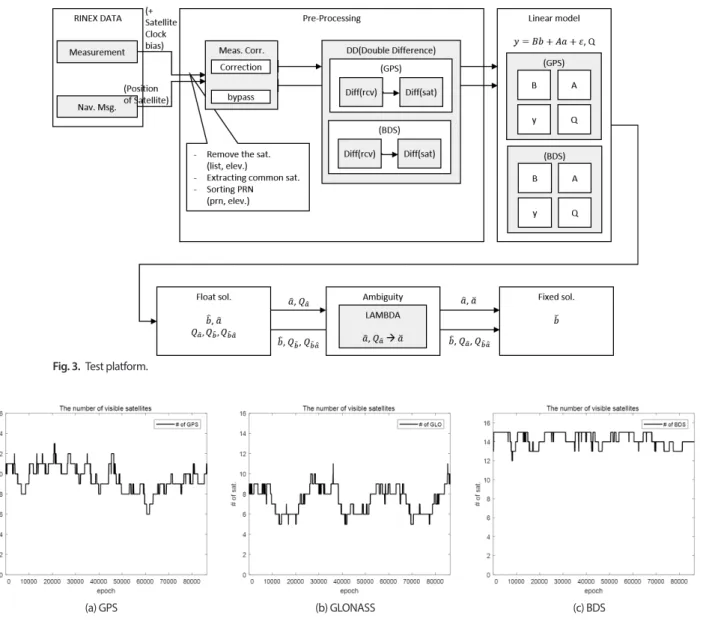
latitude. Fig. 3 is a block diagram of the platform designed for precise positioning analysis, where the linearization model is implemented by using the double differenced code and carrier phase measurements obtained in the preprocessing phase, to estimate the fixed solution, float solution, and integer ambiguity. In order to assume an environment where GNSS signals are blocked due to the high-rise buildings in an urban area, the platform was designed to block satellites below the mask angle.
3.2 The Results of Observing Visible Satellites
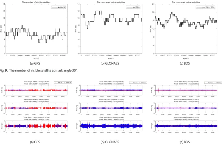
Prior to analyzing the precise positioning performance, the number of visible GPS, GLONASS, and BDS satellites that can be observed in Korea for 24 hours were analyzed. The signals were acquired from September 8, 2018, 21:30 (UTC+09:00) to September 9, 2018, 21:30 (UTC+09:00) and the mask angle was 5°. The visible satellites that can be observed for 24 hours derived from the GPS L1, GLONASS L1, and BDS B1 signals collected from the open area are summarized in Fig. 4 by each satellite navigation system. Here, the x-axis refers to the time and the y-axis is the number of visible satellites.
According to the results, an average of 9 GPS satellites and 7 GLONASS satellites could be observed for 24 hours. A total of 14 BDS satellites could be observed in 24 hours, which is the most among the 3 satellite navigation systems.
Fig. 2. Test setup.
3.3 Precise Positioning Performance According to the Mask Angle
Figs. 5-8 summarize the changes in the number of visible GPS and BDS satellites and the precise positioning results when the mask angle is below 20°. In an environment with a mask angle below 20°, both GPS and BDS can acquire enough visible satellites, so the float solutions of the integrated GPS/
BDS precise positioning as well as the GPS-only or BDS- only precise positioning can be estimated within 1 m for 24 hours. Where the x-axis is the time, and the y-axis refers to the 2DRMS. In terms of performing precise positioning by GPS-only, it was possible to estimate the fixed solution within 1 cm for 24 hours at a 99.8% probability in an environment with a mask angle of 10° and at a 95.97% probability in an environment with a mask angle of 20°. In terms of BDS-only, it
was possible to estimate the fixed solution within 1 cm for 24 hours at a 99.5% probability in an environment with a mask angle of 10° and at a 99.71% probability in an environment with a mask angle of 20°. In terms of the integrated GPS/
BDS precise positioning, it was possible to estimate the fixed solution within 1 cm for 24 hours at a 99.85% probability in an environment with a mask angle of 10° and at a 99.89%
probability in an environment with a mask angle of 20°.
In an environment where the mask angle was 30°, the performance of estimating the float solution and fixed solution was deteriorated due to the reduced number of visible GPS satellites. However, since BDS could acquire more visible satellites than GPS, it was possible to estimate the float solution within 1 m for 24 hours when performing BDS-only precise positioning in addition to the integrated GPS/BDS system. In terms of performing precise positioning Fig. 3. Test platform.
Fig. 4. The number of visible satellites of GPS, GLONASS and BDS for 24 hours.
(a) GPS (b) GLONASS (c) BDS
Fig. 5. The number of visible satellite at mask angle 10°.
(a) GPS only (b) BDS only (c) GPS/BDS
Fig. 6. The number of visible satellite at mask angle 20°.
(a) GPS only (b) BDS only (c) GPS/BDS
Fig. 7. Result of positioning at mask angle 10°.
(a) GPS only (b) BDS only (c) GPS/BDS
Fig. 8. Result of positioning at mask angle 20°.
(a) GPS only (b) BDS only (c) GPS/BDS
by GPS-only in an environment with a mask angle of 30°, it was possible to estimate the fixed solution within 1 cm for 24 hours at a 77.31% probability. In terms of BDS alone, it was possible to estimate the fixed solution within 1 cm for 24 hours at a 98.86% probability. In terms of integrated GPS/
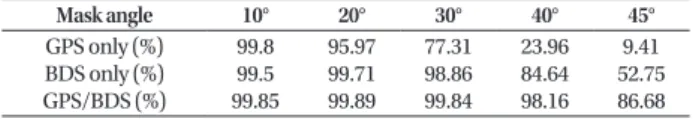
BDS precise positioning, it was possible to estimate the fixed solution within 1 cm for 24 hours at a 99.84% probability. The changes in the number of visible satellites and the precise positioning results in an environment with a mask angle of 30° are shown in Figs. 9 and 10, respectively. Where the x-axis is the time and the y-axis refers to the 2DRMS.
In an environment where the mask angle was 40°, the performance of estimating the float solution and fixed solution was deteriorated due to the reduced number of visible GPS and BDS satellites. However, since the integrated GPS/BDS system could acquire more visible satellites than the single satellite navigation systems, it was possible to estimate the float solution within 1 m for 24 hours. In terms of performing precise positioning by GPS-only in an environment with a mask angle of 40°, it was possible to estimate the fixed solution within 1 cm for 24 hours at a 23.96% probability, which indicates that it is difficult to estimate the precise position of centimeters using GPS only in an environment with a mask angle of 40° or higher.
In terms of BDS-only, it was possible to estimate the fixed solution within 1 cm for 24 hours at an 84.64% probability.
In terms of integrated GPS/BDS precise positioning, it was possible to estimate the fixed solution within 1 cm for 24 hours at a 98.16% probability. The changes in the number of visible satellites and the precise positioning results in an environment with a mask angle of 40° are shown in Figs. 11 and 12, respectively. Where the x-axis is the time and the y-axis refers to the 2DRMS.
In an environment where the mask angle was 45°, the performance of estimating the float solution and fixed solution was deteriorated or could not be estimated due to the lack of visible satellites. In terms of the integrated GPS/BDS system, the total number of observable satellites increased, but the performance of estimating the float solution and fixed solution decreased due to sections where not enough satellites were available for precise positioning.
In terms of performing precise positioning by GPS alone in an environment with a mask angle of 45°, the probability of estimating the fixed solution within 1 cm for 24 hours was 9.41%. This shows that precise positioning using GPS-only is impossible in an environment with a mask angle of 45° or higher. In terms of BDS-only, the probability of estimating the fixed solution within 1 cm for 24 hours was 52.75%, which Fig. 9. The number of visible satellite at mask angle 30°.
(a) GPS (b) GLONASS (c) BDS
Fig. 10. Result of positioning at mask angle 30°.
(a) GPS (b) GLONASS (c) BDS
Fig. 11. The number of visible satellite at mask angle 40°.
(a) GPS (b) GLONASS (c) BDS
Fig. 13. The number of visible satellite at mask angle 45°.
(a) GPS (b) GLONASS (c) BDS
Fig. 12. Result of positioning at mask angle 40°.
(a) GPS (b) GLONASS (c) BDS
Fig. 14. Result of positioning at mask angle 40°.
(a) GPS (b) GLONASS (c) BDS
shows that it is difficult to perform precise positioning with BDS-only in an environment with a mask angle of 45° or higher. However, in terms of integrated GPS/BDS precise positioning, the probability of estimating the fixed solution within 1 cm for 24 hours was 86.68%. This shows that it is possible to estimate the fixed solution at the cm level for most of the time, except for cases where the integrated GPS/BDS system has less than 7 visible satellites. The changes in the number of visible satellites and the precise positioning results in an environment with a mask angle of 45° or higher are shown in Figs. 13 and 14, respectively. Where the x-axis is the time and the y-axis refers to the 2DRMS.
Table 2 summarizes the probabilities of the GPS-only, BDS-only, and integrated GPS/BDS systems having a position accuracy within 1 cm for 24 hours according to changes in the mask angle. When using the integrated GPS/BDS system, the probability of obtaining a position accuracy within 1 cm for 24 hours in 86.68% until the mask angle is 45°, and when performing GPS-only and BDS-only precise positioning, the performance of estimating the precise position is degraded when the mask angle exceeds 40°.
4. CONCLUSION
In order to analyze the possibility of using BDS in urban canyon, this study assumed an environment similar to urban canyon by using the mask angle, and used the GPS L1 and BDS B1 signals to analyze the change of visible GPS and BDS satellites and the precise positioning performance according to the increase of the mask angle. In terms of performing precise positioning using a single satellite navigation system when the mask angle is 40° or higher, the estimating performance deteriorated or the navigation became impossible due to the reduced number of visible satellites. However, the integrated GPS/BDS system showed a high precise positioning performance due to the increase in the total number of visible satellites even in an environment with a mask angle of 40°, the success rate of estimating the fixed solution at cm level was about 86.68% even in an environment with a mask angle of 45°. Through this study, it was confirmed that it is highly possible to perform precise positioning within 1 cm even at high mask angle when using the integrated GPS/BDS system compared to using the GPS-
only or BDS-only.
The results of this study showed that it is worth using BDS along with GPS for research on the positioning of land transportation and autonomous driving technologies.
However, research on vehicle driving tests are required in actual urban canyon in future since there are influences of signal delay and interference problems including multi-path as well as GNSS signal blocking by high-rise buildings in actual urban canyon.
ACKNOWLEDGMENTS
This research was supported by a grant (18TLRP-C113269- 03) from Transportation & Logistics Research Program funded by Ministry of Land, Infrastructure and Transport of Korean government.
AUTHOR CONTRIBUTIONS
The Manuscript with several authors, a short paragraph specifying their individual contributions must be provided.
The following statements should be used “conceptualization, S. Y. and J. H.; methodology, S. Y.; software, J. H.; validation, J. H., S. Y. and D. W.; formal analysis, J.H.; investigation, J.H.; resources, J. H.; data curation, J. H.; writing-original draft preparation, J. H.; writing-review and editing, D. W.;
visualization, J. H.; supervision, S. J.; project administration, S. Y.; funding acquisition, S .J.”. Authorship must be limited to those who have contributed substantially to the work reported.
CONFLICTS OF INTEREST
Authors must identify and declare any personal circumstances or interest that may be perceived as inappropriately influencing the representation or interpretation of reported research results. Declare conflicts of interest or state “The authors declare no conflict of interest.”
REFERENCES
Chen, J., Wang, J., Zhang, Y., Yang, S., Chen, Q., et al. 2016, Modeling and Assessment of GPS/BDS Combined Precise Point Positioning, Sensors, 16, 1151-1163.
https://doi.org/10.3390/s16071151 Table 2. Results of precise positioning of different systems with different
mask angles.
Mask angle 10° 20° 30° 40° 45°