Journal of the Korean Institute of Electrical and Electronic Material Engineers, Vol. 23, No. 1, p. 6, January 2010.
6
23-1-2
논 문
UV 처리된 유리기판위에 RF-스퍼터된 PTFE 박막들의 발수 특성
Hydrophobic Properties on RF-sputtered PTFE Films coated on UV-treated Glass Substrates
손진운1, 윤현오2, 배 강2, 손선영2, 김화민2,a
(Jinwoon Son1, Hyon-O Youn2, Kang Bae2, Sunyoung Sohn2, and Hwa-Min Kim2,a)
Abstract
Surface properties of polytetrafluoroethylene(PTFE) films fabricated by rf-magnetron sputtering system with UV surface treatment were investigated to increase water contact angle for their hydrophobic property. We found that the surface morphology and water contact angles of PTFE film modified as a function of the UV treatment times using UV-irradiation were influenced. The water contact angle of PTFE film with optimized UV treatment time for 15 minute showed a high hydrophobicity compared with the film without any surface treatment. We thought that it was due to the energy change of PTFE surface with an adhesion improvement to the glass surface as a smoothing a rough surface with needle-shape and/or the enhancement of an interface property as a removing some defects on the surface like a cleaning effect.
Key Words : RF-magnetron sputtering, PTFE, Hydrophobicity, Water contact angle, UV treatment
1. 서 론
1)폴리테트라플루오로에틸렌(polytetrafluoroethylene, PTFE)은 탄소와 불소로 이루어진 고분자로서 높 은 기계적 강도와 열적 안정성 및 낮은 유전상수 를 가져 절연 특성이 뛰어나고, 화학적 물질에도 안정한 특성을 가지므로 다양한 분야에서 PTFE에 대한 연구가 활발히 진행되어지고 있다. 뿐만아니 라 sputter, e-beam evaporation과 같은 물리적 증 착법 또는 chemical vapor deposition(CVD)와 같 은 화학적 방법에 의해 제작된 PTFE는 발수특성 을 가진다. 일반적으로 물에 대한 접촉각이 90도 이상의 경우를 발수성(소수성), 110도-150도면 고
1. 울산대학교 전기전자정보시스템공학부 2. 대구가톨릭대학교 전자공학과 (경북 경산시 하양읍 금락1리 330) a. Corresponding Author : [email protected] 접수일자 : 2009. 10. 14
1차 심사 : 2009. 11. 23 심사완료 : 2009. 12. 4
발수성, 150도 이상이면 초발수성으로 여긴다. 특 히, 초발수성은 자가 세정, 비접착성, 물 부식 방지
등의 특성을 가지고 있어서 미세유체 소자
(microfluidic device), 직물 산업(textile industry), 결빙 방지품(anti-icing application)과 같은 공업 분야에 응용 가능한 소재로써 큰 관심을 받고 있 다. 그러나 PTFE의 낮은 표면 에너지 때문에 금 속 전극과의 접착 특성이 좋지 못하므로 전처리 공정이 필요하며, 화학적 그래프팅, 플라즈마 처리, 이온빔 조사, UV 조사 등의 표면 개질법들이 주로 사용되고 있다. 일반적으로 화학적인 방식에 비해 UV 처리와 같은 물리적 방식에 의한 표면 개질은 깨끗한 공정과 대면적 처리가 가능하며 환경적인 문제에도 안정하다. 또한 초발수 특성을 나타내기 위해서는 나노 사이즈의 표면 거칠기와 낮은 표면 에너지를 가져야 한다.
본 연구에서는 UV 조사(irradiation)를 이용하여 다양한 시간으로 표면 처리된 유리 기판위에 고주 파 마그네트론 스퍼터링(rf-magnetron sputtering) 장치를 이용하여 매우 낮은 표면 에너지 18∼20
전기전자재료학회논문지, 제23권 제1호, 2010년 1월
7 dynes/cm를 가지는 PTFE 박막들의 광학적 및 구 조적 특성과 접촉각 변화를 측정하였다.
2. 실 험
본 실험에서 사용되는 스퍼터링 타겟은 PTFE Powder(F7 type, Solvay)를 2시간의 볼밀과정을 거친후에 300oC에서 소성과 11톤의 압착 과정을 통하여 타겟을 고형화 하였다. 제작된 PTFE 타겟 을 이용하여 RF-magnetron sputtering 장치에 의 해 Ar 분위기에서 소다라임 유리 기판 위에 제작 된 PTFE 박막은 2x10⁻³ Torr의 진공도에서 RF 50 W의 인가전압으로 박막의 두께는 450 nm로 증착하였으며, 자외선(ultraviolet, UV)을 이용하여 표면처리 시간에 따른 PTFE 박막 표면의 발수 특 성을 분석하였다. 제작된 박막의 표면 구조를 분석 하기 위해서 Tecsco사의 원자 힘 현미경(atomic force microscope, AFM)을 이용한 이미지 분석을 하였고, 물에 대한 발수 특성을 측정하기 위해서는 Kruss 사의 접촉각 측정장치(Contact angle Analyzer) 를 이용하였으며, ULVAC-PHI 사의 X-선 광전자 분광기(X-ray photoelectron spectroscopy, XPS)를 이용하여 제작된 PTFE 박막들의 성분 분석을 하 였다. UV 처리 시간에 따른 PTFE 박막 표면의 변화 양상을 관찰하기 위해 Jeol 사의 전계방사형 주사전자현미경(field emission scanning electron microscopy, FE-SEM)으로 측정 하였다. 또한 박 막의 광학적 특성은 자외 및 가시선 분광분석법 (UV-Visible Spectrophotometer(UV-Vis. Shimadzu Co.)를 사용하여 200-800 nm의 파장영역에서 광 투과도를 측정하였다. PTFE 박막의 두께는 박막 두께측정장치(ɑ-step, VEECO Co.)을 사용하여 측 정하였다.
3. 결과 및 고찰
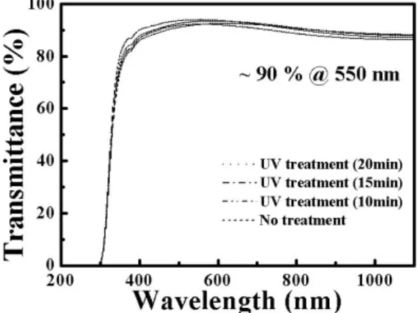
그림 1은 유리 기판위에 UV 처리시간 변화에 따른 PTFE 박막들의 투과도를 나타낸 것이다.
UV 처리 시간이 10분에서 20분으로 증가함에 따 라 PTFE 박막의 투과율은 가시광 영역에서 평균 85% 이상의 투과율을 보이고 있다. 본 실험에서 제작된 PTFE 박막들은 높은 광투과 특성을 요구 하는 디스플레이에 적용하기에 매우 적합하다.
그림 2는 rf-magnetron sputtering에 의해 제작된 PTFE 박막에서 유리 기판위에 UV 표면처리 시간 에 따른 물에 대한 접촉각 변화를 나타낸 그래프 이다. 아무런 처리를 하지 않은 박막은 약 101도의
그림 1. UV 처리시간에 따라 표면 개질된 유리위 에 제작된 PTFE 박막들의 투과율.
Fig. 1. Transmittance of PTFE films deposited on surface modified glasses as a function of UV-treatment times.
그림 2. UV 처리시간에 따라 표면 개질된 유리 위에 제작된 PTFE 박막들의 접촉각 변화.
Fig. 2. Change of water contact angle on PTFE films deposited on surface modified glasses as a function of UV-treatment times.
접촉각을 가지며, UV 표면 처리된 유리 기판위에 제작된 박막들은 접촉각이 증가된 소수성이 향상 된 특성을 보이고 있다. 특히, 15분 동안 UV 처리 된 기판위에 형성된 PTFE 박막에서 가장 높은 접 촉각을 나타내는 원인은 그림 3의 다양한 UV 처리 시간을 갖는 유리 기판위에 제작된 PTFE 박막들 의 SEM 이미지로부터 설명될 수 있다.
J. of KIEEME(in Korean), Vol. 23, No. 1, January 2010.
8 그림 3. UV-조사를 이용해 다양한 표면 처리 시
간을 갖고 개질된 유리기판위에 제작된 PTFE 박막들의 SEM 이미지.
Fig. 3. SEM images of PTFE films deposited on glass substrate modified with various surface treatment times using UV-irradiation.
그림 3(a)에서 아무런 표면 처리를 하지 않은 유리 기판위에 형성된 PTFE 박막은 표면에 큰 돌 기들이 보이는 반면에 그림 3(b)-(d)에서와 같이 UV 조사를 이용해 표면 처리된 PTFE 박막들은 큰 돌기들이 사라지고 수십-수 나노 크기의 작은 돌기들을 갖는 것을 확인하였다. PTFE 박막 표면 에서 발수 현상을 향상시키기 위한 가장 중요한 요인은 표면의 미세구조에 갇힌 공기의 역할로써 박막 표면이 나노 사이즈의 표면 거칠기를 가져야 한다. 특히, 그림 3(c)에서와 같이 15분 동안 UV 처리된 박막의 표면은 일정한 패턴을 갖는 형상을 하고 있으므로 그림 2에서 물에 대한 접촉각이 가 장 높게 나타났다고 사료된다.
그림 4는 rf-마그네트론 스퍼터링 방법에 의해 제작된 PTFE 박막에서 AFM 측정결과 아무런 표 면처리를 하지 않은 박막 표면과 UV 조사에 의해 표면 처리된 박막의 표면 형상들을 비교한 것이다.
제작된 박막의 두께는 450 nm로 고정하였으며, 그 림 4(a)의 아무런 표면처리 하지 않은 박막의 표면 거칠기(root mean square, RMS)가 1.127 nm인 것 에 비해 그림 4(b)에서 UV 처리된 PTFE 박막의 RMS 값은 0.739 nm로 감소된 결과를 보인다. 또
(a) (b)
그림 4. (a) 아무런 표면처리를 하지 않은 유리 기판과 (b) 15 분동안 UV 표면 처리된 유리 기판위에 제작된 PTFE 박막들의 AFM 이미지.
Fig. 4. AFM images of PTFE films deposited on glass substrates (a) without any surface treatment and (b) with UV surface treatment for 15 min.
한, UV 처리하지 않은 기판위에 형성된 PTFE 박 막의 표면은 침상 모양의 거친 표면을 갖는다. 이 러한 거친 표면을 갖는 박막은 넓은 접착 면적에 의해 접착력이 향상 될 수는 있으나 그 위에 금속 막과 같은 물질들을 증착할 경우 낮은 반사도와 높은 비저항을 야기한다. 반면, UV 표면 처리된 기판위에 형성된 PTFE의 특성은 표면 개질된 평 탄한 형상을 갖는다. 이는 UV 처리가 기판 표면의 불순물 제거 및 화학적 변화로 인해 기판과 PTFE 박막 사이의 계면 특성을 향상시켰기 때문으로 사 료된다.
4. 결 론
본 연구는 PTFE 타겟을 이용하여 rf- magnetron sputtering 장치에 의해 제작된 박막에 서 UV 조사(irradiation)에 의해 표면이 개질된 유 리 기판이 박막의 소수성에 끼치는 영향에 대해 분석하였다. 450 nm의 동일한 두께의 조건에서 PTFE 박막들은 가시광 영역에서 평균 85% 이상 의 높은 광투과율을 가지는 반면에 UV 표면처리 되지 않은 박막의 접촉각이 101도인 것에 비해 15 분 동안 UV 처리된 기판위에 형성된 PTFE 박막 은 113도의 향상된 고발수성을 가진다. 이는 최적 화된 UV 처리 시간에 의해 표면 처리된 유리 기 판은 표면의 불순물 제거 및 화학적 변화로 인해 기판과 PTFE 박막 사이의 계면 특성을 향상시킬
전기전자재료학회논문지, 제23권 제1호, 2010년 1월
9 뿐만 아니라 그 위에 형성되는 PTFE 박막 표면의 미세구조를 변화시켜 일정한 패턴을 갖는 형상을 가짐으로써 발수 특성을 향상 시켰다고 사료된다.
따라서 적절한 표면을 갖는 기판을 사용할 경우, 스퍼터링 방법에 의해 제작된 PTFE 박막으로부터 접촉각이 150도 이상인 초발수 특성도 기대할 수 있을 것으로 기대된다.
감사의 글
본 연구는 대구가톨릭대학교 교내 연구비 지원에 의한 것임.
참고 문헌
[1] P. Smith and P. J. Lemstra, "Ultra-high- strength polyethylene filaments by solution spinning/drawing", J. Mater. Sci., Vol. 15, p.
505, 1980.
[2] P. J. Rae and E. N. Brown, "The properties of poly(tetrafluoroethylene) (PTFE) in tension", Polymer, Vol. 46, p. 8128, 2005.
[3] 김익준, 이선영, 문성인, “ELC용 Carbon- PTFE 전극의 제조 및 전기화학적 특성”, 전 기전자재료학회논문지, 18권, 9호, p. 833, 2005.
[4] P. Machetta, M. Lazzarino, S. Carrato, C.
Schmidt, G. Canil, V. Kapeliouchko, T. Poggio, and A. Sanguineti, "PTFE nanoemulsions as ultralow-k dielectric materials", Mater. Sci.
Semicond. Process, Vol. 5, p. 285, 2003.
[5] L. Ylianttila and J. Schreder, "Temperature effects of PTFE diffusers", Opt. Mater., Vol. 27, p. 1811, 2005.
[6] Y. W. Yang, C. W. Chen, Y. Z. Wu, and Y.
C. Chen, "High performance circuit boards
based on mesoporous silica filled PTFE composite materials", Elec. Sol.‐Stat. Lett., Vol. 8, p. 1, 2005.
[7] C. J. Rong and T. Wakida, "Studies on the surface free energy and surface structure of PTFE film treated with low temperature plasma", J. Appl. Polym. Sci., Vol. 63, p.
1733, 1997.
[8] Y. Okuda, F. Hayashi, H. Sakurai, and M.
Shiotani, "A spectroscopic study on defluorination of poly(tetrafluoroethylene) by alkyllithium/electron-donating solvents", J.
Appl. Polym. Sci., Vol. 94, p. 923, 2004.
[9] D. J. Wilsion, R. L. Williams, and R. C.
Pond, “Plasma modification of PTFE surfaces”, Surf. Inter. Anal., Vol. 31, p. 385, 2001.
[10] C. Z. Liu, J. Q. Wu, L.Q. Ren, J. Tong, J.
Q. Li, N. Cui, N. M. D. Brown, and B. J.
Meenan, "Comparative study on the effect of RF and DBD plasma treatment on PTFE surface modification", Mater. Chem. Phys., Vol. 85, p. 340, 2004.
[11] L. Guzman, B. Y. Man, A. Miotello, M.
Adami, and P. M. Ossi, "Ion beam induced enhanced adhesion of Au films deposited on polytetrafluoroethylene", Thin Solid Films, Vol. 420-421, p. 565, 2002.
[12] Y. Haruyama, T. Ideta, H. Ishigaki, K.
Kanda, and S. Matsui, "X-ray photoelectron spectroscopy study of synchrotron radiation irradiation of a polytetrafluoroethylene surface", Jpn. J. Appl. Phys., Vol. 42, p. 1722, 2003.
[13] 권순일, 양계준, 송우창, 임동건, “SF6, C4F8, O2 가스변화에 따른 실리콘 식각율과 식각 형태 개선”, 전기전자재료학회논문지, 21권, 4 호, p. 305, 2008.