A Study on Application of Finite Element Method to the Impact test for the Safety of the Splash Guard of a CNC Machine Tool
Tae Won Kima, Jin Woo Choia*
CNC 공작기계 스프레쉬 가드의 안전성을 위한 충격 시험에 대한 유한요소법 적용에 관한 연구
김태원a, 최진우a*
a Research Center, Hyundai WIA, 8F #462-18, Samdong, Uiwang, Gyeonggido, 437-815, Republic of Korea
ARTICLE INFO ABSTRACT
Article history: This study addresses theissue of safety of the splash guard of a computer numerical control (CNC) machine tool at the design stage. As an impact test for evaluating safety requirements such as strength under the safety regulation is an expensive and iterative task, it is necessary to develop a new method to minimize the task of the impact test for development of the machine tool. In this study, explicit finite element method was adopted forreplacement of the impact test of the splash guard of a machine tool at the design stage. A finite element model was developed for implementing the impact test on an actual vertical CNC lathe and then produced the analysis including plastic strain and deformation to enable the safety of its splash guard to be determined. The analysis results demonstrated that the finite element method can be applied to safety evaluation for design of the splash guard of a CNC machine tool.
Received 20 June 2013 Revised 25 August 2013 Accepted 4 October 2013
Keywords:
Safety regulation Machine tool safety Impact test Splash guard
Explicit finite element method
* Corresponding author. Tel.: +82-31-596-1233 Fax: +82-31-596-1299
E-mail address: [email protected] (Jin Woo, Choi).
1. Introduction
A user of a machine tool with CNC (computer numerical control) is exposed to mechanical, electrical, and chemical hazards[1]. The user’s exposure to the hazards such as a revolving workpiece, a high voltage of electric motor, or coolant mist may cause a great injury. Prevention of the exposure requires protection devices including coolant mist suction device.
Regulations have been issued to protect users of machine tools from these hazards.
A guard is used to prevent chips generated from machining or coolant to be splashed by enclosing the working space of a machine tool. The splash guard shall protect users from a piece broken off high revolving parts such as a workpiece. The revolving workpiece clamped by the chuck of a lathe spindle can be disjoined from the chuck and then thrown to the user if the clamping force is insufficient to restrain the centrifugal force of the workpiece. This case may occur by a user’s mistake.
The disjoined object may have a large kinetic energy to cause a physical damage such as bone fracture in its collision with
(a) Test equipment
(b) Shape of the projectile Fig. 1 Simplification of the impact test a human being. A splash guard needs to be strong enough to
sustain disjoined objects.
It is necessary to consider some factors in designing a splash guard. The factors include technical performance such as strength, manufacturing, and cost. It is mostly made of sheet metal. If the thickness of the sheet is increased to improve the strength against disjoined objects, it leads an increase in weight and material cost as well. It hinders also manufacturability by increasing bending stiffness. An optimal design of a splash guard needs to be made for strength and other criteria.
A European Standard (ES) defines the safety of the splash guard of a small numerically controlled machine tool[2]. The guard should protect its user from the danger of a disjoined object. The standard defines an impact test to evaluate the safety strength of a splash guard. The impact test should be performed to produce the safety evaluation report for a small turning center and then, the turning center can be exported with the safety report. The impact energy is determined according to the size of the machine tool. It is necessary to design the splash guard to satisfy the safety regulation.
A method needs to be developed to evaluate the safety strength of a splash guard at the design stage. The actual impact test takes much time and cost and, in addition, requires an actual test object. It is difficult to manufacture actual test objects of all design candidates. These reasons may disable the actual impact test to be used for the safety evaluation at the design stage. Accordingly, it is necessary to develop a new method to replace or minimize the task of the impact test.
Much research has been carried out on many fields of machine tools such as motors, cutting, feeding systems, thermal deformation[3-6]. However, little research has been performed on safety issues[7]. In this study, research was carried out on the issue of the safety of a splash guard and focused on identification of a new method to be used for evaluation of the safety strength at the design stage.
In this study, finite element method was adapted as a new method for the impact test. It was applied to a small turning center (CNC lathe). A finite element (FE) model was developed for analysis of the safety strength of the splash guard of the machine tool. The result from the finite element analysis (FEA) was used to evaluate the safety strength at the design stage.
2. Impact test for the safety evaluation
The ES defines the procedure of the actual impact test and the assessment criteria[2]. It also defines the equipment and the test details including the size of the projectile. Fig. 1 shows the impact test of the ES. It is composed of a gas chamber, a projectile, a barrel, and a test object shown in Fig. 1(a). The chamber filled of high pressurized air shoots the projectile through the barrel to the test object, which is, in this study, the splash guard of a small turning center. The size and the velocity of the projectile at the far end of the barrel are defined according to the size of the turning center, especially, the diameter of its chuck and its rotational speed[2]. The projectile has a sharp shape at the head which hits the test object at the speed defined.
The safety criteria are defined for the impact test. Posterior to the projectile impact, examination is carried out to identify any damage to the test object, the splash guard in this study.
The damage can be classified generally into the three mechanical failures of buckling, crack, and loosening. The satisfaction to the test especially for a small turning center requires neither through-crack including penetration at the impact site of the splash guard nor loosening from its support. For instance, when
(a) A vertical turning center
(b) A splash guard of the machine tool Fig. 2 A machine tool and its splash guard
the projectile collides with the front door of a splash guard, the door should not either have any through-crack at the collision site or be loosened from its guide way in order to pass the impact test.
3. Machine tool and its splash guard
Fig. 2 shows a vertical turning center[8] and its splash guard for this study. It has a chuck of the diameter, 381 mm, and a jaw of the mass, 2.2 kg with the rotational speed of 2000 RPM. The front door has two rollers on the rail fastened to the splash guard. The hook bracket of the door was designed to be hooked to the rail.
The glass compound is composed of a reinforced glass of 5.0 mm thickness and a polycarbonate sheet of 9.5 mm to absorb the impact energy. The glass compound secures a sufficient strength against the impact. However, the door was designed to be made of a single sheet of 2.3 mm panel of cold rolled
carbon steel (KS D 3512: SCP1). Especially, the door was evaluated with the impact test in this study.
Details of the impact test were determined based on the diameter of the chuck and its tangential velocity. They determined the projectile size, speed, and, therefore, the impact energy. Using Equation (1) where N is the rotational speed of 2000 RPM and r is the chuck radius of 190.5 mm in this study, the velocity is calculated into 39.7 m/s for the machine tool.
60
2 N r
Vtg= π× ×
(1)
The velocity of, approximately, 40 m/s leads to selection of 50 mm for the diameter (D) of the projectile shown in Fig.
1 (b), 30 mm for the rectangle width (a), 2.5 kg for its mass, and 50 m/s for the impact velocity at the ES. The length (L) of the projectile is determined to be 171 mm due to the mass.
Therefore, the impact energy was determined into 3125 J with the velocity of 50 m/s and the mass of 2.5 kg using Equation (2).
2 V2
E =m× (2)
4. Application of finite element method
In this study, a new method was used to replace the impact test. It was explicit finite element method (FEM) using the commercial FEM tool, ABAQUS/Explicit. This method has been widely used for evaluation of crash or stamping with high speed dynamic material behavior[9-11]. Comparisons were made between the result of collision simulations by the FEM tool and their corresponding experimental result and then led to a good agreement in terms of energy absorption and post- deformation between them[9-13].
Equation (3) and (4) express implicit FEM and explicit FEM, respectively. The explicit FEM is based on acceleration while the implicit one is on displacement. One great difference between
Fig. 3 Finite element model for the impact test
Table 1 Property of the materials used for FEA Material
Property
Elastic
modulus (GPa) Poisson's ratio Density (kg/m3)
SCP1 210 0.29 7.81×10³
Ploycarbonate 2.3 0.37 1.2×10³
Reinforced glass 7.5 0.25 1.48×10³
Structural steel 206 0.29 7.81×10³
Fig. 4 Plastic stress-strain curve of KS D 3512 the implicit and explicit FEMs is force convergence. The explicit
one does not require convergence for force equilibrium at each time step with multiple iterations and thus it does not fail especially to solve local large deformation problems[14] such as impact or crash[12,13].
{F} = [K]{u} (3)
{F} = [M]{a} (4)
4.1. Development of a finite element model
The impact test was implemented into development of a finite element model shown in Fig. 3. The panels of the splash guard and the door were constructed of shell elements and other parts such as brackets and the projectile were of solid elements.
The element size was generally 10 mm as the splash guard is considerably large. It led to 139 divisions in length, 65 in width, and 183 in height, respectively. The number of element divisions is considered to be appropriate to describe the deformation of the splash guard under impact. However, a fine mesh is generated at the impact area to express the large deformation with a great strain. The element size was 5 mm.
Accordingly, the whole FE model had 142,284 elements including solid elements and 101,534 nodes in total.
The projectile was located between the glass and the splash guard due to a high possibility that the projectile would loosen the door from the splash guard or penetrate the door panel.
It was touched to the door panel, as shown in Fig. 3, with the initial velocity of 50 m/s defined by the ES.
The splash guard is practically fixed to the bed and thus was constrained in all six degrees of freedom at the bottom in the FE model. It is a partial model of the total splash guard and thus was symmetrically constrained at both sides with X translation constrained.
Table 1 presents the materials and their properties used for the components and thus for FEA. The splash guard is made of cold rolled carbon steel (KS D 3512: SCP1) and the glass compound is of the polycarbonate and the reinforced glass.
Other structural components such as brackets are of the structural steel with the material properties in Table 1.
Fig. 4 shows the plastic stress-strain curve of cold rolled carbon steel (KS D 3512: SCP1) obtained with tensile tests[15]. It was used for the explicit finite element analysis (FEA). Its ultimate tensile strength is 390 MPa at the plastic strain of 0.26 as shown in Fig. 4. As the impact point is not on the glass but on the door panel, the glass compound would not plastically deformed and, therefore, it is not necessary to obtain the plastic strain of the materials of the glass compound for the FEA.
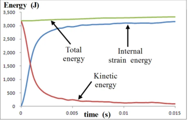
Fig. 5 Variation in the impact energy
(a) Principal plastic strain
(b) Deformation by the impact
Fig. 6 Strain and deformation of the splash guard 4.2 Result of the finite element analysis
Analysis was carried out based on the FE model. The time increment for the FEA was 0.00075 second and the total analysis time was 0.015 second. The computation of the FEA took 6 hours and 30 minutes in the workstation computer of 12 CPUs of 3.06 GHz and 34 GB RAM. The computation time can be reduced if the total number of the finite elements is reduced with a large element size for the domain except the collision site of interest. The domain may include the splash guard and the glass.
Fig. 5 shows the variation in the energies with respect to time. The kinetic energy includes the kinetic energy of the projectile and that of the door panel. The internal strain energy is the sum of the energy to deform finite elements. The total energy in Fig. 5 is that of the total analytical system which is the FE model including the projectile in this study.
It is the sum of the kinetic and strain energies and nearly constant because it is the total system energy. The kinetic energy is dramatically decreased while the strain energy is increased.
This is because the kinetic energy is converted into the strain energy as finite elements are deformed either elastically or plastically.
Fig. 6 shows the maximum principal strain and the deformation of the splash guard and the door. They can be used to determine the probability of the crack initiation and the loosening of the door. The greatest principal strain is 0.287 and therefore exceeds the ultimate tensile strain of 0.26 shown in Fig. 4. Accordingly, a crack is likely to be initiated but not to grow large enough
for the projectile to penetrate it because the strain is much localized. A further FEA, say, for crack growth, needs to be carried out if the quantity of penetration is required to be identified.
The gap between the door and the splash guard is initiated and grows up to 25 mm. However, the door, especially the inserted part into the guard, remains contacted with the guard as shown in the section view of Fig. 6 (b). The contact stiffness prevents the door from being loosened. Therefore, it can be concluded from the FEA that the door is safe from both the through-crack and loosening of the ES regulations.
The impact area of the door is similar to the front of the projectile in shape and size as shown in Fig. 6 (a) and (b).
The four vertexes of the projectile front made the four vertexes
at the impact area yielding a great strain at each vertex. The projectile pushed the impact area approximately 27 mm forward from the panel of the door shown in Fig. 6 (b). The high velocity of the projectile rapidly deformed the impact area before its kinetic energy was propagated into the neighboring area. This is a characteristic of impact such as abrupt object collision[9-13].
An actual experiment of the impact test needs to be performed to be compared with the FEA for its verification and validation even though it is predicted from Ref. 9~13 that they will lead to a good agreement because of a relatively simple collision.
The experiment will be used to verify replacement of the actual impact test with the explicit FEA and thus it can negate manufacturing of the actual splash guard with great time and cost.
5. Conclusion
This study addresses the issue on evaluation of the safety of the splash guard of a machine tool at the design stage. It is necessary to develop a new method to replace the impact test, for the safety issue, whose procedure is defined, especially, by the European Standard.
In this study, explicit finite element method was adapted to replacement of the impact test of a machine tool at the design stage. The impact test was implemented into the finite element model developed in this study. The FEA result, such as plastic strain and deformation, helped to evaluate the strength of the door against a through crack and loosening.
The FE model was applied to a actual vertical turning center and led to the following conclusions.
1) The kinetic energy of the projectile of the impact test was absorbed into the splash guard as strain energy (internal energy). The total energy which is the sum of the kinetic and strain energies remained nearly constant following energy conservation.
2) The strain and the deformation of the door of the splash guard were usable to determination of through-crack and
loosening as the criteria of its safety.
3) An actual experiment of the impact test needs to be carried out for verification and validation of the FE simulation. The experiment may be able to determine replacement of the actual test with the FEA leading to a great reduction in time and cost.
References
[1] Worker's compensation board of British Columbia 2006, Safeguarding Machinery and Equipment; General Requirements, Worker's compensation board of British Columbia (http://www.worksafebc.com).
[2] EN12415 2002, Safety of machine tools - Small numerically controlled machines and turning centres, European Committee for Standardization.
[3] Jeong, Y. H., Min, B. K., Cho, D. W., Lee S. J., 2010, Motor Current Prediction of a Machine Tool Feed Drive Using a Component-Based Simulation Model, IJPEM, 11:4 597-606.
[4] Choi, J. W., 2012, Mechatronic analysis for feeding a structure of a machine tool using multi-body dynamics, KSMTE, 21:5 691-696.
[5] Lee, C. H., Choi, J. W., 2013, Evaluation of Thermal Characteristics of a Direct-Connection Spindle Using Finite Element Co-Analysis, KSMTE, 22:2 228-234.
[6] Kim, T. W., Choi, J. W., 2013, Evaluation of Thermal Characteristics for a Feeding Axis of Machine Tools Using Finite Element Analysis, KSMTE, 22:3 380-387.
[7] HEMA, 2011, Machine Safety Window; Impact Test, HEMA,, Germany (http://www.hema-schutz.de) [8] Hyundai WIA, 2011, LV500R;Vertical Turning Center
(Catalog), Hyundai WIA, South Korea (www.wiamachine.
co.kr).
[9] Lee, C. H., Choi, J. W., 1987, Crash Simulation of Bumpers, Computers & Structures, 26:5 741-747.
[10] Iqbal, M. A., Rai, S., Sadique, M. R., Bhargava, P., 2012, Numerical Simulation of Aircraft Crash on Nuclear Containment Structure, Computers & Structures, 243 321-335.
[11] Azaouzia, M., Lebaalb, N., Rauchsa, G., Belouettara, S., 2012, Optimal design of multi-step stamping tools based on response surface method, Simulation Modeling
Practice and Theory, 24 1-14.
[12] Wiśniewski, K., Kołakowski, P. 2003, The effect of selected parameters on ship collision results by dynamic FE simulations Finite Elements in Analysis and Design, 39:10 985–1006.
[13] Dirschmid, F., Hooputra, H., Mader, H.U., Werner, H.
2005, Migration of Crash Simulation Software at BMW
ABAQUS Users’ Conference
[14] ABAQUS, 2012, ABAQUS Manual: Version 6.12, Dassault Systems.
[15] Hyundai WIA, 2011, Tensile test of the cold rolled carbon steel (KS D 3512: SCP1) in sheet (Internal Material Test Report), Hyundai WIA, South Korea.
![Fig. 2 shows a vertical turning center [8] and its splash guard for this study. It has a chuck of the diameter, 381 mm, and a jaw of the mass, 2.2 kg with the rotational speed of 2000 RPM](https://thumb-ap.123doks.com/thumbv2/123dokinfo/5115980.576183/3.892.120.378.139.607/shows-vertical-turning-center-splash-guard-diameter-rotational.webp)