- 150 -
유압펌프시스템의 직접 순시 토오크 제어
Jianing Liang, 이동희, 안진우 경성대학교
Direct Instantaneous Torque Control of Hydraulic Oil Pump System
Jianing Liang, Dong-Hee Lee, Jin-Woo, Ahn Kyungsung University
Abstract — In hydraulic oil pump system, pressure has a linear relationship with output torque of motor. Torque control of pump drive can easily output stable pressure, and it can retain required pressure at minimum speed to save power consumption. Switched reluctance motor(SRM) has many advantages such as low cost and low inertia. It can generate high torque at low speed. But inherent high torque ripple of SRM influences performance of pressure control in hydraulic oil system.
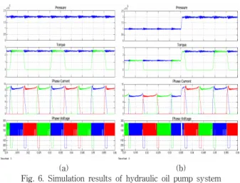
This paper presents direct instantaneous torque control(DITC) of hydraulic oil pump system. DITC method can reduce inherent torque ripple of SRM, and output smoothing torque to load. So the proposed hydraulic oil pump system can support smooth pressure and fast dynamic power supply to the hydraulic pump system. At last the proposed hydraulic oil pump system is verified by computer simulation and experimental results.
1. Introduction
A hydraulic pump system is very widely used in building machinery, brake system of vehicles and automatic control system of industrial applications[1]. In a conventional hydraulic pump system, induction motor is much used due to the cost and simplicity of the motor driving. But it has more power consumption at pressure retained. Recently, saving power consumption and high performance motor drive for hydraulic pump system is much interested in hydraulic pump system[2].
Switched Reluctance Motors(SRM) is investigated for wide industrial applications due to the mechanical strength and cost advantages. Comparing with conventional hydraulic pump system, SRM has a widely variable speed range which can save power consumption at pressure maintenance. And it can generate high torque at low speed, which obtains fast dynamic pressure response as pump system required.
This paper presents direct instantaneous torque control(DITC) of hydraulic oil pump system. DITC method can reduce inherent torque ripple of SRM, and output smoothing torque to load. Since pressure has a linear relationship with output torque of motor, the proposed hydraulic oil pump system can stable pressure and fast dynamic power supply to the hydraulic pump. At last the proposed hydraulic oil pump system is verified by computer simulation and experiment results.
2. Proposed DITC of SRM in hydraulic oil pump system
2.1. Basic concept of hydraulic pump
For hydraulic pump system with SR drive, the maximum torque and rated speed are obtained from the mechanical specifications of hydraulic pump. The maximum flux of hydraulic pump is determined by volume efficiency and pump speed as follows:
max m p
Q = n v ⋅ (1) where, Qmax is maximum output flux,
nm is pump speed,
VP is pump capacity [cm
3/min].
And the pressure of oil is determined with the assumption of constant output flux and no loss of hydraulic pump as follows:
Pp= T v
m/
p (2) where
Pp is oil-pressure [MPa], T
mis pump torque [Nm].
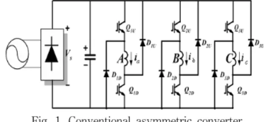
2.2. Conventional asymmetric converter for SR drive The conventional asymmetric converter can provide independent control of each phase and phase overlap, which is essential condition for DITC operation. The conventional asymmetric converter and its operating modes are shown in Fig. 1 and Fig. 2.
Fig. 1. Conventional asymmetric converter
The asymmetric converter has three modes, which are defined as magnetization mode, freewheeling mode and demagnetization mode.
The magnetization mode is defined as state 1 shown in Fig. 2(a).
The freewheeling mode is defined as state 0 shown in Fig. 2(b). The demagnetization mode is defined as state -1 shown in Fig. 2(c).
(a) (b) (c)
Fig. 2. Operation modes of asymmetric converter (a) Magnetization mode (b) Freewheeling mode (c) Demagnetization mode
2.3. Proposed DITC method for SR drive
In order to eliminate a torque ripple, DITC method is introduced.
Fixed frequency PWM is popular in a motor control. But fixed frequency of PWM brings a fixed switching loss, which reduces efficiency of drive system. Hysteresis control generates variable frequency of PWM, so frequency of power switches can be reduced.
By the given hysteresis control rules, appropriate torque of each phase can be produced and constant total torque can be obtained. In this method, the phase inductance has been divided into 3 regions shown as Fig. 3.
Fig. 3. Principle of 3 regions DITC method
2007년도 대한전기학회 하계학술대회 논문집 2007. 7. 18 - 20
- 151 -
The regions depend on the geometrical structure and load. The boundaries of 3 regions are θ
onB, θ
1B, θ
2Band θ
onCin Fig. 3. θ
onBand θ
onCare turn-on angle of phase B and phase C, respectively.
The θ
1Bis a rotor position which is the inflexion of inductance in phase B. And θ
2Bis mid point of inductance in phase A. Total length of those regions is 120 electrical degrees in 3 phases SRM.
Assuming the outgoing phase is phase A and incoming phase is phase B in Fig. 3. When the first region 3 is over, the outgoing phase will be replaced by phase B in next 3 regions.
In order to carry out the principle of 3 regions DITC method, hysteresis controller and hysteresis rules are used in control system.
The two different control schemes will be assigned to 3 regions.
DITC scheme of conventional converter is shown in Fig. 4. In order to reduce switching frequency, every action just opens or closes only one switch at a time. It can reduce frequency of the switches. In DITC scheme of asymmetric converter, region 1 and region 2 have same control scheme shown in Fig. 4(a). Combinatorial states of (-1, 1), (0, 0), (0, 1) and (1, 1) are selected into this control scheme.
Torque error is importance input parameter in proposed DITC method. If torque error satisfies the condition of rising or falling rule, actual state will turn to next combinatorial state. Jumping state is not accepted in this hysteresis control. As a similar, control scheme in region 3 is shown in Fig. 4(b).
Phase A (1,1)
(-1,0) 1
(0,1)
(0,0)
-1
Phase B SA
SB
Tref-Test 0(0)
Vdc(1)
-Vdc(-1) Phase B Phase A
Tref-Test 0(0)
Vdc(1)
-Vdc(-1) 0
-err err
0
-err err
Err>0
Err>err Err<0
Err>err Err<0
Err<-err
(a)
Phase A (-1,1)
(-1,0) 1 Phase B
(-1,-1)
SA
SB
Tref-Test 0(0)
Vdc(1)
-Vdc(-1)
Tref-Test 0(0)
Vdc(1)
-Vdc(-1)
Phase B Phase A
0
-err err
0
-err err
Err>0Err>err Err<-errErr<0
(b)
Fig.4. DITC scheme of conventional converter (a) control scheme 1 (b)control scheme 2 Control diagram of DITC SRM hydraulic oil pump system is shown in Fig. 5. Because of DITC of SRM, hydraulic oil pump system can output smooth pressure and fast dynamic flux response.
Test
CT Swiching
Table +
-
*
Tref
Torque Estimation
θ Encoder Torque Estimation
Hysteresis Controller
Converter SRM
IA
IB
IC
Pump
Tank
(- 1, 0) (1 ,1 )
1 ( 0, 1 )
(0 ,0 )
-1 E rr >0
Er r >e rr Er r <0
Err>errErr<0
E r r< - e rr
(- 1, 1 )
1
( -1 , -1 ) Err>0Err>errErr<-errErr<0
Actuator PI
*
Pref + -
Preal
Valve Solenoid
Valve