Sensorless Speed Control of Induction Motor by Direct Torque Control with Numerical Model
Kyoung-Kuk Yoon1․Sung-Hwan Kim†
(Received April 27, 2012; Revised June 14, 2012; Accepted August 27, 2012)
Abstract: Various control algorithms have been proposed for the speed-sensorless control for an induction motor. These control schemes are mainly based on the speed feedback with the flux and speed estimations.
This paper proposes another method for the speed-sensorless control for an induction motor. The proposed scheme is based on the torque and flux compensation without speed estimations, in which the same controlled stator voltage is applied to both the induction motor and the numerical model so that the differences between torques and fluxes of the model and the induction motor may be compelled to give access to zero. The results of experiment show the effectiveness of the scheme.
Key w ords: Numerical model, induction motor, direct torque control, speed-sensorless control.
†Corresponding Author (Division of Marine System Engineering, Korea Maritime University, E-mail: [email protected], Tel: 051)410-4265)
1 Director of research institute of SEANET, E-mail: [email protected] Tel: 010-5541-0424
1. Introduction
The variable-speed drive of an induction motor is usually attained by the application of a speed sensor. However, there are many problems in case of using speed sensor. The sensor requires a mounting space on the motor, reduces the reliability, and increases cost of the drive system. Therefore various speed sensorless control algorithms have been proposed for the elimination of sensors[1-5].
The scheme by numerical model is on the basis of compensating current difference between the induction motor and its numerical model, in which the identical stator voltage is supplied for both the actual motor and the model so that the gaps between stator currents of the two can be forced to decay to zero as time proceeds. Consequently, the rotor speed approaches to the model speed, namely, setting value and the system can control motor speed precisely[6-10].
And the Direct Torque Control (DTC) controls torque and flux by restricting the flux and torque
errors within respective hysteresis bands, and motor torque and flux are controlled by the stator voltage space vector using optimum inverter switching table[11, 12].
This paper proposes another sensorless speed control scheme of an induction motor by DTC with numerical model, which requires neither shaft encoder, speed estimator, transformation of reference frame nor PI controllers.
(a)
(b)
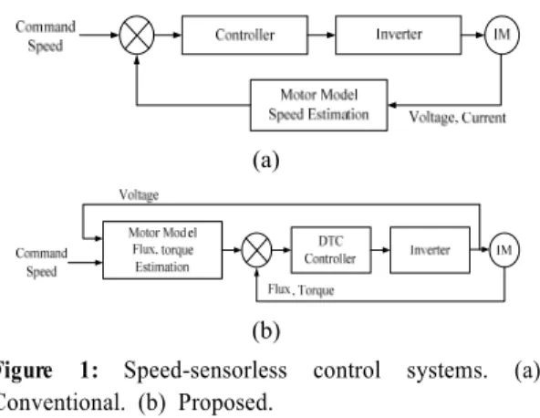
Figure 1: Speed-sensorless control systems. (a) Conventional. (b) Proposed.
Figure 1 (a) and (b) show the block diagrams of the conventional and proposed systems. The performance of the proposed scheme is verified through experiment.
2. Principles of the Proposed Scheme
2.1 Sensorless Control by the Numerical Model[1]
The voltage equation of an induction motor in the stationary reference frame variables is given by (1).
(1) where is rotor angular speed and is the differential operator.
Using matrix inversion, the voltage equation (1) can be rearranged into a current equation as follows.
(2) where,
According to equation (2), an induction motor can be regarded as a multi-variable inputs/outputs system as shown in Figure 2. In this system the input variables are the stator voltages and are modulated through the electrical and mechanical parameters, and the output variables are the stator currents and rotor speed.
Figure 2: Input and output variables of induction motor
Here, let's assume a numerical model represented by equation (2). Figure 3 shows a model where the input and output variables are newly established.
The subscript denotes the variable of the model, and is the command rotor speed of the model.
Figure 3: Input and output variables of numerical model
From the induction motor of Figure 2 and the numerical model of Figure 3, the following inference is possible. If both the stator currents of the motor and model are forced to be the same in case where both the stator voltages are the same, the motor speed becomes the same as the model speed which is the speed command. In other words, if and in case of
and , then . But because above electrical quantities are alternating values, for controlling speed by making currents of the motor and its model approach, the transformation to the synchronously rotating reference frames is requisite.
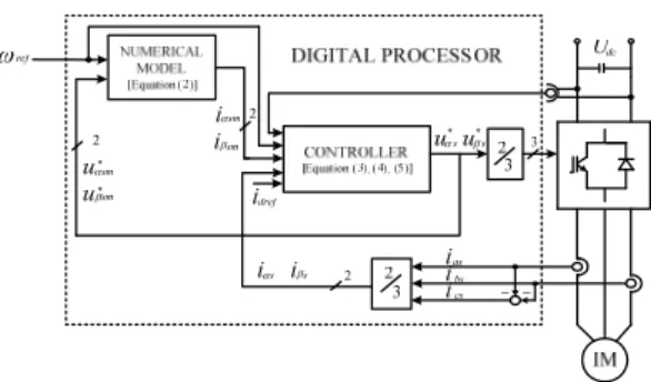
Figure 4 shows the overall block diagram of this sensorless control scheme.
For the realization of the above the control quantity of the -axis stator voltage, and -axis stator voltage for the constant flux control may be obtained by the aid of indirect field-orientation algorithm as follows:
Figure 4: Block diagram of the overall system
(3)
where, , , and are the gains.
cos sin
sin cos
(4)
(5)
where is the time constant of rotor, is command current for constant flux and
is the angle of the -axis of the synchronously rotating reference frame.
and are also the voltages applied to the motor, and is also the field angle used for the transformation between the motor voltages and currents in the stationary and synchronously rotating reference frame.
2.2 Direct Torque Control[2]
The electromagnetic torque developed by an induction motor can be expressed in a number of ways, one of which is equation (6).
sin (6)
where is the number of pole pairs, is the total leakage inductance, is the angle between the stator flux vector and rotor flux vector , often known as torque angle and , are the magnitudes and . This equation indicates that
can be directly controlled by .
The main variable to be controlled in the DTC scheme is the stator flux vector and relates the stator voltage vector as follows.
(7)
The equation shows that the derivative of reacts instantly to changes in . The stator voltage
, which is the inverter output voltage, can be controlled by the reference vector in the space vector modulation. Since is synthesized by the stationary voltage vectors of the inverter, a proper selection of the stationary vectors can make the magnitude and angle of adjustable.
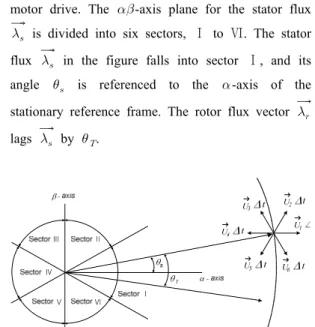
Figure 5 shows the principle of DTC for a two level VSI(voltage source inverter) fed induction motor drive. The -axis plane for the stator flux
is divided into six sectors, Ⅰ to Ⅵ. The stator flux in the figure falls into sector Ⅰ, and its angle is referenced to the -axis of the stationary reference frame. The rotor flux vector lags by .
Figure 5: Principle of direct torque control
Figure 6 shows the typical block diagram of a DTC induction motor drive. Both flux and torque comparator are of hysteresis(tolerance band) types.
The flux comparator has two output levels(
=+1,-1) while the torque comparator has three output levels(=+1,0,-1), where '+1' requests an increase in or , '-1' demands a decrease in or , and '0' signifies no changes.
Figure 6: Block diagram of DTC scheme
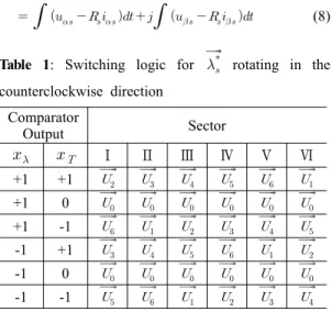
Table 1 gives the switching logic for the stator flux reference
rotating in the counterclockwise direction. The input variables are , and the sector number, and the output variables are the inverter voltage vectors.
The stator flux vector in the stationary frame can be expressed as equation (8).
(8) Table 1: Switching logic for
rotating in the counterclockwise direction
Comparator
Output Sector
Ⅰ Ⅱ Ⅲ Ⅳ Ⅴ Ⅵ
+1 +1 +1 0 +1 -1 -1 +1 -1 0 -1 -1
from equation (8), the stator flux magnitude and angle are as below.
(9)
tan
(10)
where ,, and are the measured stator voltages and currents. The developed electromagnetic torque can be also calculated by equation (11)
(11)
The above equations illustrate that the stator flux and developed torque can be obtained by using measured stator voltages and currents.
2.3 Proposed Control Scheme
As described in 2.1, if the identical voltages for both the motor and its model are forced toward making the gap between their currents zero, the voltages and the currents of induction motor will become same as those of the numerical model, then the rotor speed will approach to its model speed or the reference speed. According to equations (8) and (11), the stator flux and the developed torque of induction motor depend on its voltages and currents. Therefore, by controlling the stator flux and toque of induction motor to be equalized with those of the model instead of their currents, the same results as mentioned previously will be possible. We can also expect simpler and faster responses by means of DTC method described in 2.2.
Because this control scheme requires neither the transformation of reference frame nor complicate calculation, it will show robust characteristics against noises and the variation of parameters.
Figure 7 shows the overall block diagram of the sensorless control scheme proposed in the present paper. Controlled variables and stator flux angle for DTC are as following equations.
∆ (12)
∆ (13)
tan
(14)
Figure 7: Block diagram of the proposed control system
3. Experiments and Discussions
The experiment is performed for the verification of the proposed scheme. The rated power and speed of the induction motor are 3 hp and 1750 rpm , the rated voltage and frequency are 220 V and 60 Hz, and the motor parameters are as follows.
Table 2: Parameters of induction motor Stator Resistance(Rs) 2.0 Ω Rotor Resistance(Rr) 1.8 Ω
Rotor Leakage
Inductance(Llr) 4 mH Stator Leakage
Inductance(Lls) 4 mH Mutual Inductance(Lm) 180 mH
The microprocessor system is used for the digital processing of the proposed scheme. The sampling period is 100.
Figure 8 shows the experimental speed responses in case of no loads and the speed commands of 10 rpm and 50 rpm.
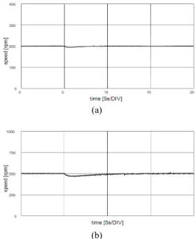
Figure 9 shows the experimental speed responses in case where the load torques of 10 N·m are applied during the operation of speed commands, 200 rpm and 500 rpm.
0 5 10 15 20
time [5s/DIV]
0 5 10 15 20
speed [rpm]
(a)
(b)
Figure 8: Experimental speed responses (a) speed command 10 rpm (b) speed command 50 rpm
(a)
(b)
Figure 9: Experimental speed responses in load variation (a) 200 rpm, 0→10 N·m (b) 500 rpm, 0→
10 N·m
(a)
0.0 0.5 1.0 1.5 2.0
time [0.5s/DIV]
-12 -6 0 6 12
CURRENT [A] : ias
(b)
Figure 10: Experimental speed response and phase current responses during the bidirectional operation (300→-300 rpm) (a) speed response (b) phase current response
(a)
0.0 0.2 0.4 0.6 0.8
time [0.2s/DIV]
-15 -10 -5 0 5 10 15
CURRENT [A] : ias
(b)
Figure 11: Experimental speed response and phase current responses during step changes of the speed commands(0→500→ 1000 rpm) (a) speed response (b) phase current response
Figure 10 shows the speed and the phase current responses during the bidirectional operation of the speed command ±300 rpm at no load.
Figure 11 shows the experimental speed and the phase current response during step changes of the speed commands at no loads. As a result of the experiments, in comparison with the method using indirect vector control, the proposed scheme expresses similar speed responses and a little higher torque ripples by 1.5~2times.
4. Conclusion
This paper has proposed another sensorless control scheme without the speed sensor or speed estimations where the speed of an induction motor indirectly follows the model speed by forcing the difference between stator flux and torque of the model and motor to decay to zero.
Because the proposed scheme to control stator flux and torque by means of DTC instead of currents requires neither the transformation of reference frame nor complicate calculation, it shows faster responses, more robust characteristics against noises and variations of parameters, and a little higher torque ripple. The experiment has been conducted for the verification of the proposed system, and the results show good speed responses.
References
[1] Young Ahn Kwon and Sung Hwan Kim, “A new scheme for speed-sensorless control of induction motor”, IEEE Transactions on Indudtrial Electronics, vol. 51, pp. 545-55, 2004.
[2] Bin Wu, High power Converter and AC Drive NewYork, IEEE Press, 2006.
[3] Paul C. Krause, Oleg Wasynczuk and Scott D.
Sudhoff, Analysis of Electric Machinery; New York, IEEE Press, 1994.
[4] K. Ohyama and K. Shinohara, “Small signal
stability analysis of vector control system of induction motor without speed sensor using synchronous current regulator,” IEEE Transactions on Industry. Applications., vol.
36, pp. 1169-1675, Nov. /Dec., 2000.
[5] V. Vasic and S. Vukosavic, “Robust MRAS based algorithm for stator resistance and rotor speed identification,” IEEE Power Engineering.
Review, vol. 21, no. 11, pp. 39-41, 2001.
[6] L. Salvatore, S. Stasi and F. Cupertino,
“Improved rotor speed estimation using two Kalman filter based algorithms,” in Conf. Rec.
IEEE-Industry Applications Society Annual.
Meeting, pp. 125-132, 2001.
[7] J. I. Ha, M. Ohto, J. H. Jang et al., “Design and selection of AC machine for saliency based sensorless control,” in Conf. Rec.
IEEE-Industry Applications Society Annual.
Meeting, pp. 1155-1162, 2002.
[8] Y. Zhang,C. Jin and V. Utkin, “Sensorless sliding mode control of induction motors,”
IEEE Transactions on Indudtrial Electronics., vol. 47, pp. 1286-1297, 2000.
[9] A. Derdiyok, M. K. Guven, H. Rehman, N.
Inanc, and L. Xu, “Design and implementation of a new sliding mode observer for speed sensorless control of induction machine,” IEEE Transactions on Indudtrial Electronics, vol. 49, pp. 1177-1182, 2002.
[10] P. Vas, Artificial Intelligence Based Electrical Machines and Drives, London, U.K., Oxford University, Press, 1999.
[11] P. Vas, Sensorless Vector and Direct Torque Control of AC Machine, London, U.K., Oxford University, Press, 1998.
[12] J. R. G. Schofield, “Variable speed drives using induction motors and direct torque control”, in IEEE Colloquium. Vector Control Revisited, pp. 5/1-5/7, 1998.
![Figure 10: Experimental speed response and phase current responses during the bidirectional operation (300→-300 rpm) (a) speed response (b) phase current response (a) 0.0 0.2 0.4 0.6 0.8 time [0.2s/DIV]-15-10-5051015](https://thumb-ap.123doks.com/thumbv2/123dokinfo/4836994.282657/6.786.88.380.105.451/figure-experimental-response-responses-bidirectional-operation-response-response.webp)
