대형의료기기의 회로 단락시 전류흐름에 대한 시뮬레이션 연구
최도순*
A study on simulation to current flow by short circuit of medical machine
Do-Soon Choi*
요 약
대형의료기기는 환자 진단과 치료 행위에 있어서 매우 중요한 기기이다. 이런 대형의료기기를 사용하여 환 자를 진단 또는 치료할 때 의료기기의 회로 내에서 갑작스런 전류의 변화는 회로의 단락 등 매우 심각한 문 제를 일으킨다. 특히 회로 내에서 전류변환기에 큰 부하가 걸리게 한다. 이것으로 인해 변환기는 포화에 이르 게 되는데 이것은 철심코일 인턱터의 magnetic curve에 기인한다. 이와 같이 변환기가 saturate에 이르게 되면 1차 측과 2차 측의 변환 비율이 깨지게 되고 회로가 단락되는 문제가 발생하게 된다. 이 논문 에서는 대형의료기기에 사용되는 current 변환기의 입력 측에 갑작스런 큰 전류 변화가 발생 했을 때 일어나는 그에 따른 포화 상태와 그의 2차 측 전류의 변화를 simulation 해본다.
Abstract
surgery equipment in operating room is very important at treatment procedure of patients. In this circuit of large equipment, a sudden change of current make big problem such as short circuit. when the current is converted suddenly, the current converter becomes in saturate and it caused by the induction curve of the inductor. in this case, the rates of the primary and secondary winding are broken and it becomes a open circuit. in this paper, we will look around the current transform of the primary and secondary winding when current converter becomes in saturate
Keywords: Current flow, Short circuit, Surgery equipment, Medical machine, Converter
* 교신저자 : 관동대학교 의료공학과 ([email protected])
접수일자:2012년 10월 24일, 수정일자 : 2012년 11월 23일, 심사완료일자:2012년 11월 28일
Ⅰ. 서 론
대형의료기기의 전기 회로 내에 control 목적으 로 burden을 사용한다. 이 burden은 기기 내부에 서 발생한 고장을 신속하고 정확하게 선택 차단하
는데 널리 적용되는 계전기로서 역할을 한다. 그러 나 이 burden은 많은 전력소비와 그로인한 과열현 상으로 제한적으로 사용된다.
이런 문제점으로 인하여 burden 대신에 in- ductive current 변환기를 사용한다. 그러나 in-
ductive current 변환기는 1차 측의 증가하는 과전 류와 time constant로 인해 2차 측은 쉽게 포화 상 태에 이르게 되고 이어서 단락상태에 돌입하게 된 다. current 변환기의 saturate시 1차 측 nominal current는 약 100배 정도로 커지며, 그 결과 변환 기의 1차 측과 2차 측의 proportional 상태가 깨어 지게 된다. 이 논문에서는 inductive current 변환 기의 단락 시 saturate로 인한 2차측 단락 current 을 분석하고 전류의 파형을 simulation을 통해서 알아본다.
Ⅱ. current 변환기의 특성
current 변환기 일반적으로 입력 측에 정현파 전류가 입력되었을 때와 inductance와 resistor를 고려한 input current 가 입력 되었을 때의 경우를 계산하면 다음과 같다.
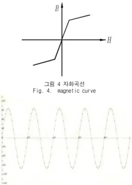
이때 current 변환기의 magnetic curve는 그림 1과 같이 변화 하는 것으로 가정 한다.
그림1 자화곡선 Fig.1 magnetization curve
보통의 permeability를 갖는 iron core는 field intensity가 계속 증가하면 induction은 saturate가 되어 그 증가 폭은 완만하게 증가하게 된다.
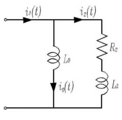
그림 2는 current 변환기의 equivalent circuit 이다.
그림2 전류변환기의 등가회로 Fig.2 equivalent circuit of current converter
이때 : principal inductance
: burden inductance
: burden resistance
: magnetization current
, : 1차측과 2차측 전류 width winding resistance 이다.
principal inductance 는 saturate 까지는 constant 이며 saturate 상태에서는 거의 zero가 된다. 그림 2로부터 다음과 같은 전류 방정식을 유 도할 수 있다.
(1)
이때=
이며
이다
식(1) 에 sin형 입력전압 = sint가 입력하 면 출력전압 (t)는
sin+
sin (2) 으로 주어진다.
이고
이다
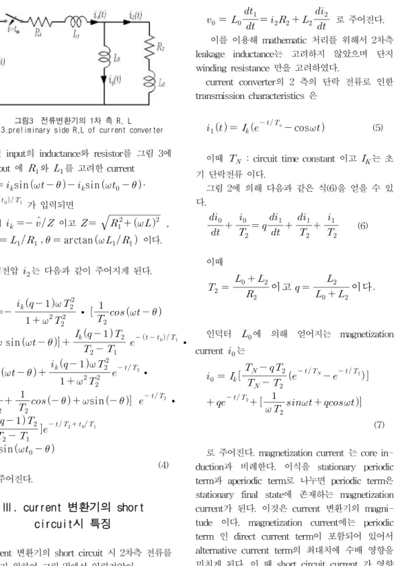
그림3 전류변환기의 1차 측 R, L
Fig. 3.preliminary side R,L of current converter
한편 input의 inductance와 resistor를 그림 3에 서 input 에 와 를 고려한 current
sin sin ·
가 입력되면
이때 이고
,
arctan 이다.
출력전압 는 다음과 같이 주어지게 된다.
·
sin
· sin
·
sin ·
· sin
(4) 로 주어진다.
Ⅲ. current 변환기의 short circuit시 특징
current 변환기의 short circuit 시 2차측 전류를 계산하기 위하여 그림 2]에서 입력전압이
로 주어진다.
이를 이용해 mathematic 처리를 위해서 2차측 leakage inductance는 고려하지 않았으며 단지 winding resistance 만을 고려하였다.
current converter의 2 측의 단락 전류로 인한 transmission characteristics 은
cos (5)
이때 : circuit time constant 이고는 초 기 단락전류 이다.
그림 2에 의해 다음과 같은 식(6)을 얻을 수 있 다.
(6)
이때
인덕터 에 의해 얻어지는 magnetization current 는
(7)
로 주어진다. magnetization current 는 core in- duction과 비례한다. 이식을 stationary periodic term과 aperiodic term로 나누면 periodic term은 stationary final state에 존재하는 magnetization current가 된다. 이것은 current 변환기의 magni- tude 이다. magnetization current에는 periodic term 인 direct current term이 포함되어 있어서 alternative current term의 최대치에 수배 영향을 미치게 된다. 이 때 short circuit current 가 영향 을 미치게 되면 saturate current 는 매우 리 나
타나게 된다.
때문에 회로가 periodic term 과 aperiodic term에 포함되어 있는 induction을 조정해야한다.
위와 같은 목적을 위해서 변환기의 burden을 작게 하거나 아니면 core의 단면적을 크게 함으로써 가 능하다. 변환기의 2차 측 전류의 direct current term은
(8) 이다. current 변환기의 direct current term은 Time constant 이 작을수록 falsification이 커 진다.
Ⅳ. simulation
current 변환기의 primary측의 변화로 saturate 상태에서 야기된 secondary current 를 유도하 기위하여 그림2 에서 유도 된 식
을 얻는다.
current 는 0에서 200[A] 까지 계산한다.
는 그림 4와 같이 linear 영역과 saturated 영역에 대하여 계산한다.
이때
이고 ∆
∆
· 이다.
그림 5 는 변환기의 normal 전산 상태에서의 secondary current 를 나타내며 그림 6은 갑작 스런 over current variation시의 를 나타낸다.
그리고 그림 7는 saturate 상태에 있을 때의 secondary current 를 나타낸다.
그림 4 자화곡선 Fig. 4. magnetic curve
그림5. 정상상태에서의 2차 측 전류 Fig.5 secondary current curve in normal state
그림 6 과전류 시 2차 측 전류 Fig. 6 secondary current in over current
그림7 포화상태 시 2차 측 전류 Fig.7 secondary current in saturate state
Ⅴ. 결 론
전류변환기의 1차 측에 흐르는 전류가 갑작스 럽게 변하게 될 때 변환기의 2차 측 전류변화를 simulation 하였다. 변환기는 1차 측에 흐르는 전 류가 갑작스럽게 변하게 되면 가능한 빨리 mili second 안에 조치가 처리 되어져야 한다. 그렇지 않으면 변환기는 변환기의 principal inductance로 인해 time constant 가 증가하고 saturate 상태에 이르게 된다. 그림 6은 saturate 상태가 아닐 때에 secondary current는 impressed current 상태인 것 을 보여주고 있다. 포화상태가 아닌 상태에서 포화 상태로 변할 때 전류는 jump 형식으로 변하지 않 고 exponential형식으로 변한다. 그 이유는 mag- netization current가 갑작스런 변화를 일으키지 않 기 때문이다. 그림 7 에 표시된 A 영역에서는 변 환기는 정상적으로 동작 한다. 이 구간에서는 magnetization current 가 나가기 때문이다. 그 러나 B영역에서는 변환기는 saturate 상태에 의해 exponential형식으로 변화 되어지는 전류를 보여주 고 있다.
참고문헌
[1]. Gernot FunkKurzshlus im Drehstro- mnetz R. OldenburgVerlag Munchen 1982 Hartmann
[2]. Der oilarme Stutzen Spannung-wandler ein newer Prazionswandler fur Hochs- pannungen. Browen Boveri Mitt Bd.33 Nr.4/5 1997
[3]. kleinshmidt. h. Stromwandler-Seconders trom im Ubers-stromgrbite Elektrie 15 (1981.s.24-29)
[4]. De Mesmaker I. Otto A Steiner der new distanzerelais feur Hoch-spannu- ngsbetze Browen Boveri Mitt Bd.33 Nr.4/5 1983[9/10 379-383]
[5]. H.Barchetti N.Korponay Behaviour of current transformers, relays and
protective devices subjected to transients. Ciger Report 31-06 1988
저자약력
최 도 순(Do-sun choi) 정회원 1972.2 숭실대학교
전자공학과 졸업 1978,6-1983.6 대한전선 주식회사 1987.6 독일 베르린
공과대학교 석사 1993.2 독일 베르린
공과 대학교 박사 1993.3 ~ 현재
관동대학교 의료공학과 교수
<관심분야> 전력전자, 전동기제어