Abstract
The construction method for Young Dong Tunnel has been chosen following detailed risk assessment. In this paper, the specific risks to the project programme, associated with adopting either mechanical excavation in the form of a shielded TBM, or drill and blast excavation methods, are assessed. From the risk assessment results, and taking other important factors into account, such as project sensitivity and local experience, the recommendation is made that the relatively low risk drill-and-blast method is the most appropriate for construction of Young Dong Tunnel.
Keywords: Young Dong Tunnel, Risk Assessment, Drill and Blast, Mechanical Excavation, Shielded TBM
*1Member, Daewoo E&C Co. Ltd., Deputy General Manager, Ph.D.
*2Halcrow China Ltd., Director, Ph.D.
*3Daewoo E&C Co. Ltd., Project Manager
*4Member, Daewoo E&C Co. Ltd., Managing Director 김용일*1
Kim, Yong-Il Hencher, S. R. *2
윤영훈*3 Yoon, Young-Hoon
조상국*4 Cho, Sang-Kook
Determination of the Construction Method for Young Dong Tunnel by Risk Assessment
위험도 분석기법에 의한 영동선 터널의 굴착공법 결정사례
1. Introduction
The major part of the Young Dong Railroad Relocation Project proposed by Korean National Railways (KNR) consists of the construction of a tunnel in rock approximately 16.3 km long with a
span of approximately 8 m. It will be the longest tunnel in Korea (Fig.1). The tunnel is designed to carry a single-track railway in a large radius loop below mountainous terrain in eastern Korea. The maximum depth of the tunnel is approximately 400 m with most of the alignment being at depths in
요 지
영동터널의 굴착공법은 다음과 같은 세밀한 위험도 분석기법을 통하여 결정되었다. 본 논문에서는 실드 TBM 과 같은 형태의 기계 화 굴착공법과 천공 및 발파에 의한 굴착공법에 따른 공사중 특정의 위험도를 분석 하였다. 공사 민감도 및 현장 경험등의 기타 중요 인자를 고려한 위험도 분석결과에 따라 본 현장여건을 고려하면 천공 및 발파공법이 영동선 터널의 굴착공법으로 가장 적합하다고 제 안 되었다.
주요어: 영동터널, 위험도 분석, 천공 및 발파, 기계화굴착, 실드 TBM
Fig.1 Young Dong Railway Relocation Project
excess of 100 m.
2. Geology of the Site
The proposed tunnel alignment passes through geological formations ranging from Cambrian to Triassic in age. Expected lithologies intercepted by the alignment include conglomerates, quartzite, sandstones, shales, limestone and coal measures.
Cretaceous volcanics also outcrop in the area but these are expected to be well above the proposed invert level (Fig. 2).
The key geological factors recognized for assessing appropriate construction methods for the tunnel are as follows:
potentially high water pressures, up to 40 bars (40 kgf/cm2)
fault zones, possibly associated with significant groundwater inflows
highly sheared and closely jointed rocks some rocks with high strength
possible karstified (cavernous) limestone with groundwater
coal measuring rocks and old mine workings
Fig. 2 Geology of the Site
3. Risk Assessment Method
A risk assessment method has been developed to make a quantitative and objective assessment of the construction methods of Young Dong Tunnel.
The risks associated with tunnel excavation are dependent on the hazards encountered and are defined with respect to programme (rather than other issues such as safety or cost).
The likelihood of a hazard occurring is assumed to be at one of three levels, thus:
1. Probable 2. Occasional 3. Remote
In turn, the degree of consequence of each hazard is assumed to be at one of five levels, namely:
1. Catastrophic 2. Critical 3. Serious 4. Marginal 5. Negligible
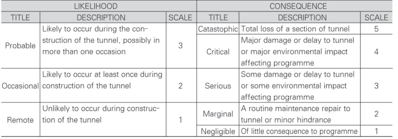
Table 1. Definition of Risk to Programme
LIKELIHOOD CONSEQUENCE
TITLE DESCRIPTION SCALE TITLE DESCRIPTION SCALE
Catastophic 5
Probable 3
Critical 4
Occasional 2 Serious 3
Marginal 2
Remote 1
Negligible 1
Table 2. Risk Classification
ConsequenceLikelihood Catastrophic Critical Serious Marginal Negligible
Probable 15 12 9 6 3
Occasional 10 8 6 4 2
Remote 5 4 3 2 1
Score
10-15 Very High Risk - not acceptable for tunnel construction - need to apply mitigation mea- sures to eliminate or reduce risk
6-9
High Risk - apply mitigation measures to eliminate or reduce risk. Residual risk at this lev- el indicates need for active management control and response plans to be well developed with well trained personnel, materials and plant readily available
1-5 Low Risk - may be accepted if mitigating measures are in place under active management control
Likely to occur during the con- struction of the tunnel, possibly in more than one occasion
Likely to occur at least once during construction of the tunnel
Unlikely to occur during construc- tion of the tunnel
Total loss of a section of tunnel Major damage or delay to tunnel or major environmental impact affecting programme
Some damage or delay to tunnel or some environmental impact affecting programme
A routine maintenance repair to tunnel or minor hindrance Of little consequence to programme
The description and scale of the above levels of likelihood and consequence are given in Table 1.
The level of risk for each hazard can be determined by finding its likelihood of occurrence and considering its consequence. The level of risk associated with the hazard is then established conventionally as follows:
Level of Risk = Likelihood x Consequence
Once the level of risk has been ascertained, it can be compared with Table 2 below to identify the
action that should be taken to mitigate the risk.
Having made an assessment of the risk associated with each hazard, appropriate mitigation measures are considered. The residual risk remaining after mitigation is then assessed in the same way to determine acceptability or otherwise.
4. Risk Assessment
The assessment of risks associated with the use of a shielded TBM to excavate a hard rock tunnel is
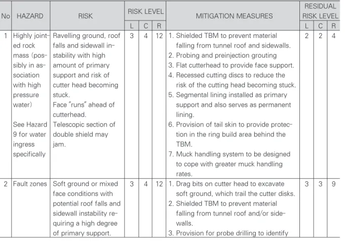
Table 3. Programme Assessment for Excavation by Shielded TBM with Segmental Lining
RESIDUAL
No HAZARD RISK RISK LEVEL
MITIGATION MEASURES RISK LEVEL
L C R L C R
1 3 4 12 2 2 4
2 3 4 12 3 3 9
Ravelling ground, roof falls and sidewall in- stability with high amount of primary support and risk of cutter head becoming stuck.
Face "runs" ahead of cutterhead.
Telescopic section of double shield may jam.
Soft ground or mixed face conditions with potential roof falls and sidewall instability re- quiring a high degree of primary support.
1. Shielded TBM to prevent material falling from tunnel roof and sidewalls.
2. Probing and preinjection grouting 3. Flat cutterhead to provide face support.
4. Recessed cutting discs to reduce the risk of the cutting head becoming stuck.
5. Segmental lining installed as primary support and also serves as permanent lining.
6. Provision of tail skin to provide protec- tion in the ring build area behind the TBM.
7. Muck handling system to be designed to cope with greater muck handling rates.
1. Drag bits on cutter head to excavate soft ground, which trail the cutter disks.
2. Shielded TBM to prevent material falling from tunnel roof and/or side- walls.
3. Provision for probe drilling to identify (L : Likelihood, C : Consequence, R : Risk)
Highly joint- ed rock mass (pos- sibly in as- sociation with high pressure water)
See Hazard 9 for water ingress specifically
Fault zones
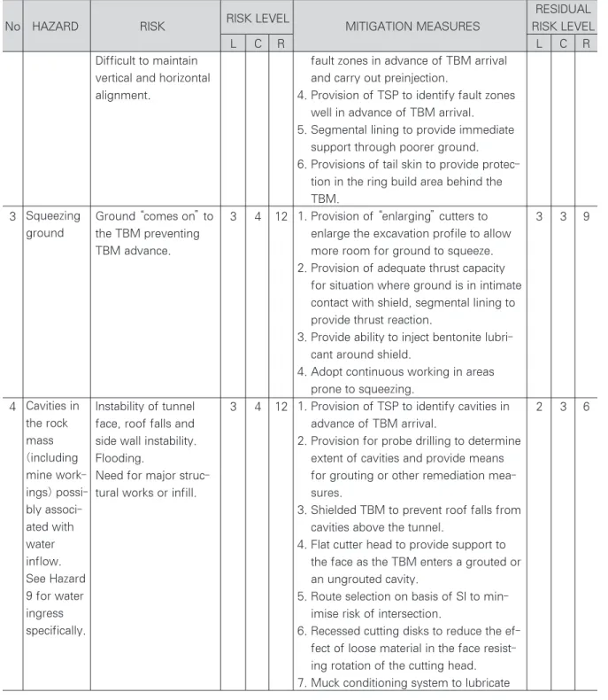
Table 3. Programme Assessment for Excavation by Shielded TBM with Segmental Lining
RESIDUAL
No HAZARD RISK RISK LEVEL
MITIGATION MEASURES RISK LEVEL
L C R L C R
3 3 4 12 3 3 9
4 3 4 12 2 3 6
Difficult to maintain vertical and horizontal alignment.
Ground “comes on”to the TBM preventing TBM advance.
Instability of tunnel face, roof falls and side wall instability.
Flooding.
Need for major struc- tural works or infill.
fault zones in advance of TBM arrival and carry out preinjection.
4. Provision of TSP to identify fault zones well in advance of TBM arrival.
5. Segmental lining to provide immediate support through poorer ground.
6. Provisions of tail skin to provide protec- tion in the ring build area behind the TBM.
1. Provision of “enlarging”cutters to enlarge the excavation profile to allow more room for ground to squeeze.
2. Provision of adequate thrust capacity for situation where ground is in intimate contact with shield, segmental lining to provide thrust reaction.
3. Provide ability to inject bentonite lubri- cant around shield.
4. Adopt continuous working in areas prone to squeezing.
1. Provision of TSP to identify cavities in advance of TBM arrival.
2. Provision for probe drilling to determine extent of cavities and provide means for grouting or other remediation mea- sures.
3. Shielded TBM to prevent roof falls from cavities above the tunnel.
4. Flat cutter head to provide support to the face as the TBM enters a grouted or an ungrouted cavity.
5. Route selection on basis of SI to min- imise risk of intersection.
6. Recessed cutting disks to reduce the ef- fect of loose material in the face resist- ing rotation of the cutting head.
7. Muck conditioning system to lubricate (L : Likelihood, C : Consequence, R : Risk)
Squeezing ground
Cavities in the rock mass (including mine work- ings) possi- bly associ- ated with water inflow.
See Hazard 9 for water ingress specifically.
RESIDUAL
No HAZARD RISK RISK LEVEL
MITIGATION MEASURES RISK LEVEL
L C R L C R
5 3 3 9 3 2 6
6 3 3 9 3 2 6
7 3 4 12 3 3 9
High UCS for rock mass causing high ram loads and increased disk cutter wear. Presence of high strength rock increasing load on mechanical components.
Main bearing wear.
Abrasive nature of rock mass causing increased rate of disk cutter wear.
Mixed face conditions causing mucking difficulties.
excavated material and reduce resis- tance to rotation of the cutting head.
1. Shallow cutting head to allow easier ac- cess to change disk cutters.
2. Double shield TBM with grippers for use in high strength rock.
3. Provision of back-loaded disk cutters to allow replacement of disks without man access to the face.
4. Provision of disk handling equipment (monorail hoist) through the TBM and back up.
5. Provide large diameter main bearing to improve cutter head access.
6. Variable speed drive to provide higher torque to cutting head.
1. Shallow cutting head to allow easier ac- cess to change disk cutters.
2. Provision of back-loaded disk cutters to allow replacement of disks without man access to the face.
3. Provision of disk handling equipment (monorail hoist) through the TBM.
4. Variable speed drive to allow for high torque to cutting head.
5. Provision of adequate supply of re- placement disk cutters and consumable parts.
6. Provide large diameter main bearing to improve cutter head access.
7. Fail-safe drive control system to prevent TBM operation when personnel are in the cutter head.
8. Provide efficient ventilation to remove dust.
1. Provision of drag bits to excavate “soft”
ground.
2. Double shielded TBM with grippers for High
strength rock
Abrasive rocks
Variable quality rock mass
RESIDUAL
No HAZARD RISK RISK LEVEL
MITIGATION MEASURES RISK LEVEL
L C R L C R
8 3 4 12 2 3 6
9 3 4 12 2 3 6
Difficulties in main- taining vertical and horizontal directions.
Failure of a major me- chanical component of the TBM e.g. main bearing, cutter head drive, hydraulics or rams.
Water in cavities, joints and fissures in the rock mass entering face during excavation and after TBM has passed. Water caus- ing instability of ground in face.
Damage to TBM electrics.
rock and rams for “soft”ground or ar- eas unable to provide gripper reaction.
3. Segmental lining to provide immediate support and thrust reaction in “soft”
ground.
4. Probe drilling to predict presence of soft ground in advance of TBM arrival.
1. Shallow cutting head to reduce moment on main bearing
2. Provision of variable speed drive to op- timise cutter head torque with ground conditions reducing overall load on main bearing and other components 3. Reversible cutting head to enable the
head to free itself if stuck in blocky/un- stable ground thereby reducing peak loading on major components
4. Recessed disk cutters to reduce load on main bearing in blocky/unstable ground 5. Provide access for inspection of bearing
by endoscope
6. Provide means of taking bearing oil samples to identify nature and quantity of any contamination
7. Provide means to replace major me- chanical components underground 8. Provide automatic bearing lubrication
with drive system override in the event of malfunction
1. Bolted segmental lining provided with compression gaskets
2. Probing and preinjection grouting 3. TBM electrical systems to be rated to
IP68 or equivalent.
4. Main bearings and critical mechanical components to be watertight.
5. Tunnel drive to be up-grade to allow water to drain by gravity from the face/build area.
Mechanical failure
Water ingress, possibly under high pressure up to 40 bar (40kgf/cm2)
RESIDUAL
No HAZARD RISK RISK LEVEL
MITIGATION MEASURES RISK LEVEL
L C R L C R
10 1 5 5 1 4 4
11 3 5 15 1 5 5
12 3 5 15 1 4 4
13 2 4 8 1 4 4
Fire in TBM or back- up caused by human error or plant malfunc- tion.
Handling segments for an 8.0m lining intro- duces risks of seg- ments being dropped during transport to the face or during erec- tion.
Possible occurrence of explosive and/or nox- ious gases; explosion
Damage to cutterhead and drive unit.
6. Tail skin to be provided with a lubricat- ed wire brush tail seal.
7. Flat cutter head and recessed disk cut- ters to reduce the potential for face col- lapse.
1. Provision of fire suppression system for TBM and back-up train
2. Use of non-flammable hydraulic oils and lubricants
3. Electrical systems to be rated to IP68 or equivalent.
1. Ensure fail-safe segment erector opera- tion by providing secondary segment lifting capacity in the event of erector system failure or power supply outage.
2. Segment handling system to be located near tunnel invert.
3. Man access to segmental lining han- dling and build area to be prevented.
4. Provide back-up TBM power supply.
1. Provision of satisfactory quantities of fresh air to the TBM and face area.
2. Provision of suitable atmosphere moni- toring system.
3. Provision of dust suppression system in cutting head.
1. Provide retrieval equipment.
Fire in TBM
Segmental lining erec- tion
Tunnel ven- tilation and atmosphere, including accumula- tion of explosive and nox- ious gases (methane etc) Broken drill string from probe drill ahead of face
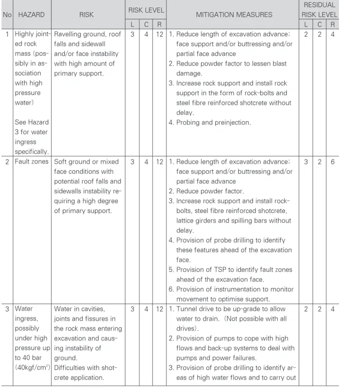
Table 4. Programme Risk Assessment for Excavation by Drill and Blast
(L : Likelihood, C : Consequence, R : Risk)RESIDUAL
No HAZARD RISK RISK LEVEL
MITIGATION MEASURES RISK LEVEL
L C R L C R
1 3 4 12 2 2 4
2 3 4 12 3 2 6
3 3 4 12 2 2 4
Ravelling ground, roof falls and sidewall and/or face instability with high amount of primary support.
Soft ground or mixed face conditions with potential roof falls and sidewalls instability re- quiring a high degree of primary support.
Water in cavities, joints and fissures in the rock mass entering excavation and caus- ing instability of ground.
Difficulties with shot- crete application.
1. Reduce length of excavation advance;
face support and/or buttressing and/or partial face advance
2. Reduce powder factor to lessen blast damage.
3. Increase rock support and install rock support in the form of rock-bolts and steel fibre reinforced shotcrete without delay.
4. Probing and preinjection.
1. Reduce length of excavation advance;
face support and/or buttressing and/or partial face advance
2. Reduce powder factor.
3. Increase rock support and install rock- bolts, steel fibre reinforced shotcrete, lattice girders and spilling bars without delay.
4. Provision of probe drilling to identify these features ahead of the excavation face.
5. Provision of TSP to identify fault zones ahead of the excavation face.
6. Provision of instrumentation to monitor movement to optimise support.
1. Tunnel drive to be up-grade to allow water to drain. (Not possible with all drives).
2. Provision of pumps to cope with high flows and back-up systems to deal with pumps and power failures.
3. Provision of probe drilling to identify ar- eas of high water flows and to carry out Highly joint-
ed rock mass (pos- sibly in as- sociation with high pressure water)
See Hazard 3 for water ingress specifically.
Fault zones
Water ingress, possibly under high pressure up to 40 bar (40kgf/cm2)
RESIDUAL
No HAZARD RISK RISK LEVEL
MITIGATION MEASURES RISK LEVEL
L C R L C R
4 3 4 12 2 3 6
5 3 5 15 1 4 4
6 3 3 9 3 1 3
7 2 5 10 1 5 5
Instability of tunnel face, roof fall and side wall instability.
Flooding.
Need for major struc- tural work or infilling.
Explosion risk. Possible accumulation of explo- sive and or noxious gas.
Methane, associated with coal or other sources is a flammable gas, lighter than air and can give rise to explo- sion. In large quantities it can also cause asphyx- iation. Other gases such carbon dioxide, carbon monoxide sulphur diox- ide and hydrogen sul- phide are noxious.
Failure of key item of plant
Premature detonation or uncontrolled explosion
pre-injection grouting to stem the flow.
4. Excavation equipment systems to be rated to IP68 or equivalent.
5. Use drainage channels to control in- flows prior to shotcreting.
1. Provision of TSP to identify cavities in advance of excavation.
2. Provision of probe drilling to determine extent of cavities and provide means for grouting or other advance stabilisa- tion measures.
3. Reduce length of excavation advance.
1. Provision of adequate fresh air from the portal to the excavation face.
2. Provision of adequate and suitable at- mospheric monitoring system.
3. Avoid the use of dry shotcrete mix.
4. Use explosive appropriate to tunnels prone to fire risk.
5. Standby generators to power fans.
1. Planned maintenance strategy.
2. Maintain spare plant items.
3. Maintain stocks of spares.
1. Employ qualified staff.
2. Comply with safety regulations.
3. Use proper storage and transport facili- ties
4. Use non-electric detonators Cavities in
the rock mass (in- cluding mine work- ings) possi- bly associ- ated with water in- flow Tunnel at- mosphere and Ventilation including accumula- tion of ex- plosive and noxious gases
Mechanical breakdown
Use of Explosives
presented in Table 3, and that for drill and blast excavation is presented in Table 4.
5. Results and Discussion
It can be seen from an initial inspection of Tables 3 and 4 that the number of hazards associated with a shielded TBM at Young Dong would be much greater than for the drill and blast method. The principal reasons for this include :
the sophistication of modern TBMs which require a high level of technological input for their successful operation and maintenance the relative inflexibility of mechanised excavation and lining systems to deal with conditions for which they may not have been specifically designed
the dependence of the tunnel progress entirely on the performance and reliability of a single item of mechanical plant.
Table 3 identifies a total of 13 significant hazards connected with the TBM method. The risk
classifications can be summarised as follows:
Thus, although it can be seen that the areas of very high risk can be successfully eliminated, the majority of the residual risk is classified as “high”,
with an average score of 6.9 (in a “high risk”range of 6 - 9, see Table 2).
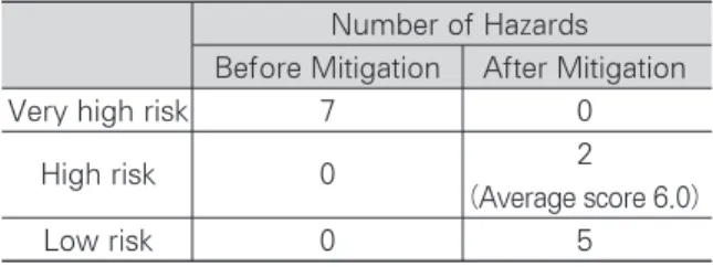
Table 4 identifies a total of 7 significant hazards connected with the drill and blast method. The risk classifications in this case can be summarised as
follows:
Again it can be seen that all areas of very high risk can be successfully eliminated, but in this case slightly more than 70% of the residual risks are classified as “low”. The residual risks in the “high risk”category have an average score of 6.0 (in a
“high risk”range of 6 - 9, see Table 2).
The average level of risk of all hazards after mitigation in each case can be summarised as below.
TBM method - No. 13 hazards in total
- average risk classification after mitigation 6.00 (marginally
“high”)
Drill and blast method - No. 7 hazards in total - average risk
classification after mitigation 4.60 (“low”) It is recognised that the above assessment of programme risk is largely qualitative and to a certain extent subjective. Also, the differences in the numerical scores are not large, although this is partly due to the simple scoring system adopted.
Number of Hazards Before Mitigation After Mitigation
Very high risk 7 0
High risk 0 2
(Average score 6.0)
Low risk 0 5
Number of Hazards Before Mitigation After Mitigation
Very high risk 9 0
High risk 3 8
(Average score 6.9)
Low risk 1 5
However, a general trend is apparent as enggested below.
there are likely to be for more significant risks which may impact on programme associated with the use of a TBM than with the drill and blast method - a total of 13 No. for TBM compared with 7 No. for drill and blast
the level of residual risk after mitigation is likely to be generally higher with a TBM than with drill and blast
6. Conclusion
1) A risk assessment method has been developed and applied to make a quantitative and objective assessment of the construction methods of Young Dong Tunnel.
2) The risk assessment results show that the drill
and blast method would be a relatively low risk approach, whereas a shielded TBM would provide a generally higher risk approach