A Comparison of the Fuzzy Display Methods for a Surface Deformation
Min-Kee Park
*★Abstract
There are several kind of surface deformation display methods using the fuzzy model. In this paper, we describe three fuzzy display methods for a surface deformation and perform a comparative analysis between the modified fuzzy display method and some conventional fuzzy display methods. In each method, the analysis will be performed through computer simulation in order to show the performance of each algorithm. The results show that the modified method have improved the realism and can be used better than the conventional methods in practical applications.
Key words: Fuzzy model, Fuzzy display, Surface deformation, Virtual environment, Realism of virtual reality
Ⅰ. Introduction
A method for displaying a surface deformation is a technique invented for achieving the realism of virtual reality(VR) simulation. Developing better algorithms for surface deformation displays, thus, are important to improve the realism of VR simulations.
The methods for displaying a surface deformation can be largely classified as vertex-based and spline-based, depending on whether the object surface is represented by polygonal meshes or parametric equations[1]. In the vertex-based method, the deformation of one vertex will impact its neighbors, and therefore the object mesh look-up table requires supplemental information. The spline-based method represents virtual objects through parametric equations. This method uses functions that are of a higher degree than the linear
* Dept. of Electronic & IT Media Engineering, Seoul National University of Science and Technology
★Corresponding author:
E-mail:[email protected], Tel: +82-2-970-6464
※ Acknowledgment:
This study was supported by Seoul National University of Science and Technology.
Manuscript received May. 22, 2013; accepted June 1 2013
functions describing a polygonal planes and provides increased surface smoothness compared to polygonal meshes. Most of the existing deformation display methods are indirect[2]. Users can not touch surfaces directly, but through some special parameters called control points, weights, and so on. In these methods, there are many control points and it is hard to predict what deformation can be obtained after several parameters’ change, even if they are defined only by control points and knot vectors.
The conventional mathematical model for displaying a surface deformation also exists, but is too difficult to encode, or is too complex to be evaluated fast enough for real time operation, or involved too much memory. To overcome the above problems, several different approaches for displaying a surface deformation have been proposed using the fuzzy model[4]-[6].
In this paper, we describe several fuzzy display methods for a surface deformation and perform a comparative analysis through computer simulation.
This paper is organized as follows. In section Ⅱ, we described several fuzzy display methods for a surface deformation. In the next section, we perform a comparative analysis between some conventional fuzzy display methods and the modified method. In section Ⅳ, we compare the performance of each
algorithm through computer simulation. Finally in section Ⅴ, a conclusion is presented.
Ⅱ. Fuzzy Display Methods for a Surface Deformation
The fuzzy display methods for a surface deformation are based on Takagi and Sugeno's fuzzy model[8] represented by fuzzy rules of the type:
and⋯ and
⋯ (1) where ⋯ denotes the th fuzzy rule,
⋯ are input variables and is an output from the th implication. Furthermore,
is a consequent parameter and ⋯ are membership functions representing a fuzzy subspace.
The overall output of a fuzzy model is given as
, (2)
where is an output inferred from the fuzzy model, is a degree of match for the th fuzzy rule and denotes the minimum operation.
Deforming actions are used to create a new fuzzy rule set that defines the deformed shape of the object and this new fuzzy rule set is added to the original fuzzy model to display a surface deformation. In this section, we describe several fuzzy display algorithms for a surface deformation.
(1) Method Ⅰ: Algorithm based on the fuzzy model whose consequent part is a constant[4]
This method is based on the fuzzy model whose consequent part is expressed by a constant. The algorithm for surface deformation displays is as follows:
Step1: Display the original surface using the fuzzy model of the type:
: If is
and is
, then (3) Step2: If a force is applied to the surface, acquire a new rule set for a surface deformation. This new rule set is in the general form of
: If is
and is
, then (4)
The parameters of the new fuzzy rule are determined as follows:
1) The value of is the coordinate of the surface without deformation. The value of depends on both the force and stiffness of the object. If a pressure is applied to the surface, the value of is altered in proportion to pressure magnitude in the fuzzy model.
2)
and
are membership functions and fully described by their modal values , and spreads , as follows:
exp
and exp
(5)where modal values and of membership function correspond to a point pushed on the surface of an object and the spreads and of the membership function determine the properties of the shape being sculpted.
Step3: Add the newly generated rule set of a surface deformation to the original fuzzy model as shown in Fig. 1 and a new fuzzy model is reconstructed to display surface deformation.
Step4: If another force is applied to the surface, repeat steps a, b and c.
rule1
rule2
rule3 rule4
x New rule
y
Fig. 1. Fuzzy partition of the input space with deformation
In the above algorithm, the in the consequent part determines the deformed depth when the surface is pushed.
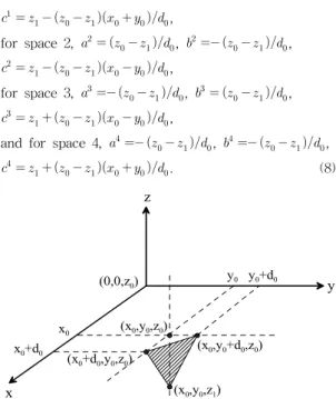
(x0+d0,y0,z0) x0+d0
(x0,y0,z0)
(x0,y0,z1) x
y z
x0
y0
(x0,y0+d0,z0) y0+d0
(0,0,z0)
Fig. 3. The graphical description of a consequent part for input space 1
rule2
rule3 rule4
x
y
rule1
(x0,y0) x0
y0
Space2 Space1
Space4 Space3
x0-d0
y0+d0
x0+d0 y0-d0
Fig. 2. Fuzzy partition of an input space for a new rule set
(2) Method Ⅱ: Algorithm based on the fuzzy model whose consequent part is a hyperplane[5]
In [5], a new algorithm was presented for surface deformation displays, which is also based on fuzzy model. This algorithm uses a hyperplane as a consequent part of a fuzzy model instead of a constant.
The steps for surface deformation displays are as follows:
Step1: Display the original surface using the fuzzy model of the type:
: If is
and is
, then (6) Step2: If a force is applied to the surface, apply a new rule set for surface deformation. This new rule set is in the general form of
: If is
≠
and is
,then (7) where (=1,2,3,4) denotes the fuzzy rule for the input space .
The input space for a new rule set is divided into four regions as shown in Fig. 2, where the coordinate corresponds to a point pressed on the surface of an object and determines the area to be deformed.
The graphical description of a consequent part for input space 1 is shown in Fig. 3. The value of is the coordinate on the surface without deformation.
The value of depends on the force.
The parameters of the new fuzzy rule are determined as follows:
For space 1, , ,
,
for space 2, , ,
,
for space 3, , ,
,
and for space 4, , ,
. (8)
The
and
are Gaussian-like membership functions as follows:
exp
and exp
(9)where modal values
and
of these membership functions correspond to the following values respectively.
For space 1,
=
and
=
, for space 2, =
and =
, for space 3, =
and =
and for space 4,
=
and
=
(10)
The values for spreads , are all defined as . Step 3: Add the newly generated rule set of a surface deformation to the original fuzzy model as shown in Fig. 1 and a new fuzzy model is reconstructed to model surface deformation.
Step4: If another force is applied to the surface,
repeat steps a, b and c.
In the above algorithm, in the consequent part determines the deformed depth when the surface is pressed.
(3) Modified method
This modified algorithm is similar to that of the method Ⅰ in that it is based on the fuzzy model whose consequent part is a constant. However, to overcome the conventional problems, a degree of match is evaluated by product operation as follows:
(11)where is a degree of match for the th fuzzy rule and
denotes the product operation.Ⅲ. Comparison of the fuzzy display methods
All the fuzzy display methods for a surface deformation described above are based on the fuzzy model. The depth of the deformation is defined by the consequent part of a fuzzy model and the region and shape of deformation is defined by membership functions. Deforming actions are used to create a new fuzzy rule set that defines the deformed shape of the object and this new fuzzy rule set is added to the original fuzzy model to model a surface deformation. However, these methods also have some similarities and differences in their representation and displays.
First, we consider a methodⅠ based on the fuzzy model whose consequent part is a constant. The most distinctive features of this method are its simplicity. The consequent part is expressed only by a constant. This simple algorithm reduce the number of calculations and is therefore computationally efficient, which allows for fast enough evaluation for real time operation. While this algorithm is simple since surface deformation is defined only by simple fuzzy rules, the shape deformed is coarse and may not seem to be accurate.
To overcome these problems, a new algorithm was
presented which expresses the consequent part by a hyperplane, not a constant as follows:
Consequent part of the method Ⅰ:
Consequent part of the method Ⅱ: In this algorithm , and are defined in equation (8) and determined by the parameters , ,
, and . Furthermore, the input space for a new rule set is divided into four regions as shown in Fig.
2 and consequent parameters should be evaluated for each input space. This means that there are many parameters and it is hard to predict what deformation can be obtained after several parameters' change.
Consequently, this algorithm has a better capability of surface deformation displays but needs more consequent parameters than method Ⅰ.
The modified method is suggested by combining the merits and removing the demerits of the two conventional fuzzy display methods. This modified method is similar to method Ⅰ in that it has the same structure as that of method Ⅰ. However a degree of match for the th fuzzy rule is evaluated by a product operation instead of a minimum operation as follows:.
Method Ⅰ: Modified method:
It is well known that a product operation is more flexible than the minimum operation in evaluation of the degree of match. And it is expected that the deformed shape is more smooth and may seem to be more true and accurate by using a product operation.
The modified method is, thus, a simple algorithm, but has a better capability of deformation description that can also be used in practical application.
In the next section, the results of the computer simulation are given to compare the performance of each method.
Ⅳ. Simulation and Considerations
This section gives some results of the computer simulation to compare the performance of each algorithm. A plane surface is represented by only one rule whose consequent part is a constant expression
as follows:
: If is and is,
then (12)
where, exp
, exp
.If a force is applied to the above plane surface, a new rule set for surface deformation is added using each algorithm. Assume that each new rule set is added for surface deformation as follows:
Method Ⅰ: If is and
y
is, then Method Ⅱ:
space 1: If is
and is
, then
space 2: If is
and is
, then
space 3: If is
and is
, then
space 4: If is
and is
, then
Modified method: If is and is, then
where we assume that a point is pushed on the surface with coordinates (20, 20).
Computing all parameters of the fuzzy model by each algorithm, we can get the corresponding fuzzy model of the surface deformation. The consequent parts in the method Ⅰ and the modified method are represented by a constant which determine the depth of the deformation. And the membership function determines the area of the deformation and properties of the shape being sculpted. Therefore, designer can easily determines which parameters should be used and how much they should be changed in order to alter shapes as they want.
In the method Ⅱ,
,
, , and are
defined in equations (8), (9) and (10) and determined by the following parameters: , , ,
and .
Thus, this method needs more consequent parameters than the method Ⅰ and the modified method and it is hard to predict what deformation can be obtained after several parameters' change.
Designer have to learn the effect of each parameter;
therefore, each time they deform forms, users have
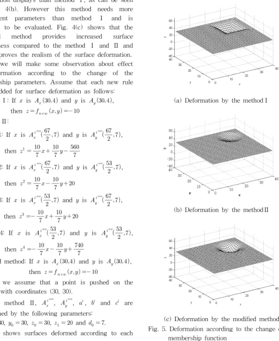
(a) Deformation by the method Ⅰ
(b) Deformation by the method Ⅱ
(c) Deformation by the modified method Fig. 4. Deformation according to each algorithm
difficulties in determining which parameters should used and how far they should be changed in order to alter shapes as they want.
Fig. 4 shows a surface deformed according to each algorithm. While method Ⅰ is simple since surface deformation is defined only by a simple fuzzy rule, the shape deformed is coarse and does not seem to be accurate as shown in Fig. 4(a). On the other hand, method Ⅱ has a better capability of surface deformation displays than method Ⅰ, as can be seen in Fig. 4(b). However this method needs more consequent parameters than method Ⅰ and is complex to be evaluated. Fig. 4(c) shows that the modified method provides increased surface smoothness compared to the method Ⅰ and Ⅱ and thus improves the realism of the surface deformation.
Next, we will make some observation about effect of deformation according to the change of the membership parameters. Assume that each new rule set is added for surface deformation as follows:
Method Ⅰ: If is and is , then
Method Ⅱ:
space 1: If is
and is
,
then
space 2: If is
and is
,
then
space 3: If is
and is
,
then
space 4: If is
and is
,
then
Modified method: If is and is , then
where we assume that a point is pushed on the surface with coordinates (30, 30).
In the method Ⅱ,
,
, , and are determined by the following parameters:
, , , and .
Fig. 5 shows surfaces deformed according to each
method. As shown in Fig. 5, if the modal values for the Gaussian-like membership function are changed, the point pushed is also changed to the position corresponding to the moral values and we can say that these moral values of the membership function correspond to a point pushed on the surface of an object. For a small value of spreads, the deformation occurs in a small neighborhood of a point pushed.
(a) Deformation by the methodⅠ
(b) Deformation by the methodⅡ
(c) Deformation by the modified method Fig. 5. Deformation according to the change of the
membership function
Large values for spreads result in deformation of wide area. Thus, users are able to control the region of deformation and the properties of the shape being deformed by adjusting the parameters of the membership function.
As can be seen in Fig. 5, the deformation represented by the modified method is more smoothly connected and more intuitively persuasive than the deformation represented by the methodⅠ and Ⅱ. In other words, the modified method has the best capability of surface deformation displays.
The above simulation studies have shown the advantages and disadvantages of the fuzzy display methods and have clearly indicated suitable performance of the modified method. Consequently, the modified method is a simple but effective technique that can easily be applied to practical applications.
Ⅴ. Conclusion
In this paper, we describe several fuzzy display methods for a surface deformation. All of the fuzzy display algorithms considered, force designers to translate surface deformations into fuzzy models and provide for various kinds of deformation.
We also perform a comparative analysis through computer simulation and show that the modified method is simple but has improved realism compared to other methods. The modified method, thus, is the most useful in displaying a 3D surface deformation and can be easily used in practical applications.
For comparative analysis, we have been dealing with an easy and well defined object here, however, the algorithms can easily be applied to more complex shape representations. As a future work, thus, more researches will be conducted on more complex shape representation and practical applications.
References
[1] Grigore C. Burdea, Force and touch feedback for virtual reality, Wiley-Interscience. New jersey, 1996.
[2] J. Yamashita and Y. Fukumi, "Direct deformation method of free forms for CAD interface", Proc. of the IEEE virtual reality annual international symposium, pp.97-104, New York, 1993.
[3] H. Yokoi, J. Yamashita, Y. Fukui and M.
Shimojo, "Development of the virtual shape manipulating system", Proc. of the fourth international conference on artificial reality and tele-existence, pp.43-48, Tokyo, 1994.
[4] Min-Kee Park, “Fuzzy displays of a surface deformation for virtual world", International Journal of Fuzzy Logic and Intelligent Systems, vol.2, no.2, pp127-132, June 2002.
[5] Min-Kee Park, “Fuzzy modeling of a surface deformation for virtual environment", International Journal of Fuzzy Logic and Intelligent Systems, vol.2, no.3, pp198-203, Dec. 2002.
[6] Min-Kee Park and Hedeki Hashimoto, “Surface deformation displays for virtual environment using the fuzzy model", IEICE Transactions on Information and Systems, vol.E87-D, no.6, pp1422-1432, June 2004.
[7] J.C. Bezdek, "Editorial: Fuzzy models-what are they and why?," IEEE Trans. on Fuzzy Systems, vol.1, pp.1-6, Feb. 1993.
[8] K. Tanaka and M. Segeno, "Fuzzy identification of systems and its applications to modeling and control," IEEE Trans. systems Man Cybernet.
vol.15, pp.116-132, Jan. 1985.
[9] M. Sugeno, T. Yasukawa, "A fuzzy-logic-based approach to qualitative modeling", IEEE Trans.
Fuzzy Systems, vol.1, no.1, pp.7-31, 1993.
[10] H.Hellendoorn, D.Driankov, Fuzzy model identification, Springer, Heidelberg, 1997.
[11] M. Park, S. Ji, E. Kim, and M. Park, "A new approach to the identification of a fuzzy model,"
Fuzzy sets and systems, vol.104, pp.169-181, 1999.
[12] E. Kim, M. Park, S. Ji, and M. Park, "A new approach to fuzzy modeling", IEEE Trans. on Fuzzy Systems, vol.5, no.3, pp.328-337, 1997.
[13] E. Kim, H. Lee, M. Park, M. Park, "A simply identified Sugeno-type fuzzy model via double clustering", Information Sciences 110, pp.25-39, 1998.
[14] A. Baris, S. Hiroaki, H. Hashimoto, M. Park, S.
Metin, "Man-machine interface for micro/nano manipulation with an AFM probe", Proc. of the
32nd International Symposium on Robotics, pp.670-675, Seoul. 2001.
BIOGRAPHY
Min-Kee Park (Member)
1985: BS degree in Electronic Engineering, Yonsei University.
1992: MS degree in Electronic Engineering, Yonsei University.
1996: PhD degree in Electronic Engineering, Yonsei University.
1985~1990: Research Engineer, LG Electronics.
2000~2001: Visiting Researcher, University of Tokyo.
1996~Present: Professor, Seoul National Univ.
of Science and Technology.