Printed in the Republic of Korea
http://dx.doi.org/10.5012/jkcs.2016.60.5.299
Physicochemical and Electrochemical Characteristics of Carbon Nanomaterials and Carbon Nanomaterial-Silicon Composites
Soo-Jin Kim, Yura Hyun, and Chang-Seop Lee*
Department of Chemistry, Keimyung University, Daegu, 42601, Korea. *E-mail: [email protected] (Received April 1, 2016; Accepted July 8, 2016)
ABSTRACT. In this study, the physicochemical and electrochemical properties of carbon nanomaterials and synthesized nano-car- bon/Si composites were studied. The nano-carbon/Si composites were ball-milled to a nano size and coated with pyrolytic carbon using Chemical Vapor Deposition (CVD). They were then finely mixed with respective nano-carbon materials. The physicochemical proper- ties of samples were analyzed using Scanning Electron Microscopy (SEM), Energy Dispersive X-ray Spectroscopy (EDS), Raman spectroscopy, X-ray Diffraction (XRD), X-ray Photoelectron Spectroscopy (XPS), and surface area analyzer. The electrochemical char- acteristics were investigated using the galvanostatic charge-discharge and cyclic voltammetry (CV) measurements. Three-electrode cells were fabricated using the carbon nanomaterials and nano-carbon/Si composites as anode materials and LiPF6 and LiClO4 as electrolytes of Li secondary batteries. Reversibility using LiClO4 as an electrolyte was superior to that of LiPF6 as the electrolyte. The initial discharge capacities of nano-carbon/Si composites were increased compared to the initial discharge capacities of nano- carbon materials.
Key words: Carbon nanomaterials, Silicon composites, Chemical vapor deposition, Lithium secondary batteries, Anode material
INTRODUCTION
Lithium secondary batteries (LSB) are energy devices that have been at the center of the mobile electronic device market for the past 20 years and they are currently being used in various electronic devices owing to rapid growth of the mobile device market.1−4 Moreover, the demand for LSB is also expected to grow rapidly from receiving attention as a Smart Grid Electrical Energy Storage System (Smart Grid ESS) that serves as a key sector of green growth and as a power source for transportation systems, such as, elec- trical vehicles (EV).1,3,5 Lately, LSB are being recognized as a promising power source because of their characteristics of high energy density and high capacity.3 In particular, much of the demand for LSB is accounted for by their charac- teristics of high energy density surface area per unit volume, high performance from excellent power density, no self-dis- charge, and long cycle life.3,6 However, the next generation LSB are required to be smaller and lighter, while also having faster charging speeds and higher energy and power den- sities. Moreover, they must also have a discharge capacity that is higher than what is available today and offer supe- rior reversibility for longer battery life.1,6−10 The key to the charging capacity of LSB, which is considered an important electrochemical parameter of batteries, is using electrode materials with high energy capacities.5,11 Consequently, vari- ous carbon materials have been studied in recent years as
anode materials in LSB for achieving a higher capacity density and thermal stability, among various cell character- istics.12−14 According to reports, carbon materials, when used as anode materials in LSB, showed significant improve- ment in cell characteristics of cycle performance and sta- bility just by storing lithium.15 However, the theoretical capacity of the carbon material was low at 372 mAh/g, which does not meet the energy size requirement in today’s market, and as such, there are active studies on using carbon nano- fibers, carbon nanotubes, and graphene for improving the capacity, retention rate, and cycle life of LSB.5,16
In the present study, carbon nanomaterials and nano- carbon/Si composites were tested as anode materials in LSB for improving its performance. Carbon materials, with excel- lent thermal stability but low theoretical capacity (372 mAh/
g), and Si, which shows volume expansion by 400% during charge/discharge in battery applications but has a high theo- retical capacity of 4200 mAh/g, were used together to prepare the nano-carbon/Si composites to improve the performance of LSB.1,4,5,16,17
The method for preparing the nano-carbon/Si compos- ites involved coating pyrolytic carbon onto Si particles via chemical vapor deposition (CVD) first, and then mixing with the carbon nanomaterial. The nano-carbon/Si com- posite prepared in this manner was used as an anode material in LSB in an effort to increase the cell capacity via the high capacity characteristics of Si and reduce the level of vol-
ume expansion through the excellent thermal stability of the carbon nanomaterial during the charge/discharge pro- cesses.
The present study investigated and compared the phys- icochemical properties of nano-carbon/Si composites that were prepared with various carbon nanomaterials, and further, applied these materials as anode materials in LSB for study- ing their electrochemical performance and characteristics.
METHODS
Materials
The carbon nanomaterials used in the present study were procured from Carbon Nano-material Technology Co., Ltd.
(Korea). To synthesize the nano-carbon/Si composite, after ball milling Si particles with size of 1–5 µm, pyrolytic carbon was coated onto Si via CVD using 20% ethylene gas (C2H4/N2).
Carbon/Si composite
Fig. 1 is a schematic diagram of the CVD apparatus used for coating pyrolytic carbon onto Si. First, Si pow- der, of diameter of 1–5 µm, and ethanol together were ball milled for 12 h, and then dried for 12 h at 80oC. Micron- sized Si prepared in this manner was evenly spread out on a quartz boat and placed into the CVD apparatus. First, for stabilization, the temperature was increased up to 900oC at a rate of 10oC/min under a flow of nitrogen gas. Then, while maintaining the temperature at 900oC for 30 min, pyrolytic carbon was coated onto Si under a flow of ethylene gas, which was the carbon source. Here, nitrogen gas was allowed to flow together to promote the gas phase reaction.
Then, the system was cooled back down to 25oC under the flow of nitrogen gas only. The flow rate of gas used for synthesis was regulated via a mass flow controller (MFC).
Si coated with pyrolytic carbon in this manner was mixed with carbon nanomaterials in a 1:1 weight ratio and ball milled for 12 h after adding ethanol. Then, the nano-carbon/
Si composites were prepared by drying for 12 h at 80oC.
Three-electrode cell fabrication
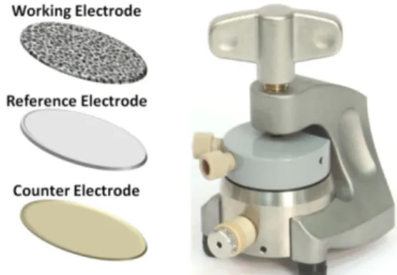
A three-electrode cell, which is depicted in Fig. 2, was constructed and used to investigate the electrochemical characteristics of the carbon nanomaterials and nano-car- bon/Si composites that had been prepared as anode mate- rials in LSB. Anode material preparation involved mixing the sample and binder, polytetrafluoroethylene (PTFE), in a weight ratio of 4:1, and adding isopropyl alcohol (IPA) to control the viscosity. After mixing in a centrifugal mixer at 2,000 rpm for 20 min, dip-coating was performed on nickel foam, the current collector. The coated nickel foam was air dried for 5 min at room temperature, and then dried for over 24 h at 80oC for use as an anode. The cell was a half-cell, which was assembled inside a glove box filled with Ar gas.
The nickel foam coated with carbon nanomaterials and nano-carbon/Si composites was used as the working elec- trode, while lithium metal was used as the counter and refer- ence electrodes. A glass fiber separator was soaked in electrolytes for use as the separation membrane. The elec- trolyte used was 1 M LiPF6 and 1 M LiClO4, with LiPF6 consisting of a solution prepared in 1:1:3 weight ratio of ethylene carbonate (EC):propylene carbonate (PC):ethyl methyl carbonate (EMC), and LiClO4 consisting of a solu- tion mixed with 1:1 weight ratio of EC:PC.
Analytic instruments
Scanning electron microscopy (SEM, Hitachi, S-4800) was used to observe the shape and size of each material. Qualita- tive and quantitative analyses on each material were per- formed via energy dispersive X-ray spectroscopy (EDXS, Thermo ARL, ARL-3460). Raman spectroscopy (Horiba Jobin-Yvon, LabRAM HR-800) was used to investigate car- bon and Si crystallinity in each material, while X-ray dif- fraction (XRD, PANalytical, X'pert PRO-MPD) was used to investigate the crystallinity of each material by looking at carbon- and Si-specific peaks. X-ray photoelectron spec- Figure 1. Schematic of CVD apparatus for the preparation of
nano-carbon/Si composites.
Figure 2. Image of the three-electrode cell for lithium secondary batteries.18
troscopy (XPS, Thermo Fisher Scientific, Multilab-2000) was used to analyze each material by measuring its bond energy, while a surface area analyzer (Brunauer Emmett Teller, BET, QUANTACHROME, Qudrasorb SI) was used to measure and analyze the specific surface area of each material. Fur- thermore, cyclic voltammetry (CV, Solartron, SI 1287) was used to investigate cell reversibility, among the electro- chemical characteristics of each material. The experiment was performed in a voltage range of 0.01–2 V (vs. Li/Li+) and a current density of 100 mA/g was applied.
RESULTS AND DISCUSSIONS
Carbon nanomaterial
SEM: SEM images of carbon nanomaterials: graphite nanofiber_antler (GNF), carbon nanofiber_platelet (CNF_P), carbon nanofiber herringbone (CNF_H), and carbon nano- tube_multi-wall (MWCNT), were measured and are dis- played in Figs. 3(a)-(d). In Fig. 3, image (a) shows GNF in upright form with a diameter of 260 nm, image (b) depicts CNF with a diameter varying between 40 and 80 nm; image (c) is similar image (b), but having relatively uniform and larger diameter than (b) of approximately 80 nm, and image (d) exhibits MWCNT with a diameter of approximately 40 nm, which was the thinnest and most densely packed form.
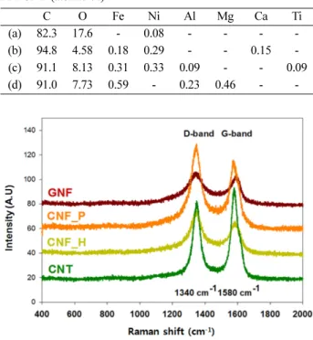
EDS: EDS measurements were taken for qualitative and quantitative analyses of specific areas of the carbon nano- materials, the results of which are listed in Table 1. Table 1 shows that the mean values of elemental carbon in GNF, CNF_P, CNF_H, and MWCNT are 82.3%, 94.8%, 91.1%, and 91.0%, respectively, which shows that these carbon nanomaterials have a high mean value of carbon element ranging between 82.3% and 94.8%.
Raman spectroscopy: Raman spectroscopy analysis was performed to compare the carbon crystallinity of the carbon nanomaterials, the results of which are shown in Fig. 4. In Fig. 4 the D-band near 1,340 cm−1 represents structural defects in graphite or a carbonaceous impurity, while the G-band near 1,580 cm−1 represents crystals of graphitized carbon. Evaluation of relative crystallinity was possible by calculating the ratio of D-band intensity to G-band intensity (D/G ratio), called amorphousity. An increase in this value represents an increase in impurities or structural defects, indicating low crystallinity, while a decrease in this value represents higher crystallinity. Table 2 lists the D/G ratio values of the carbon nanomaterials (GNF, CNF_P, CNF_H, and CNT). In (a), (b), (c), and (d) of Table 2, ID/IG ratio value was 1.0673, 1.1715, 1.2011, and 0.8842, respectively, which indicated that (d) had the lowest D/G ratio among the carbon nanomaterials, meaning it had the best crystallinity.
XRD: To investigate the crystallinity of the carbon
Figure 3. SEM images of (a) GNF, (b) CNF_P, (c) CNF_H, (d) MWCNT.
Table 1. EDS results of (a) GNF, (b) CNF_P, (c) CNF_H, (d) MWCNT (atomic %)
C O Fe Ni Al Mg Ca Ti
(a) 82.3 17.6 - 0.08 - - - -
(b) 94.8 4.58 0.18 0.29 - - 0.15 -
(c) 91.1 8.13 0.31 0.33 0.09 - - 0.09
(d) 91.0 7.73 0.59 - 0.23 0.46 - -
Figure 4. Raman spectra of GNF, CNF_P, CNF_H and MWCNT.
Table 2. Raman spectroscopy ID/IG ratio of (a) GNF, (b) CNF_P, (c) CNF_H, (d) MWCNT
Sample D/G ratio
(a) GNF 1.0673
(b) CNF_P 1.1715
(c) CNF_H 1.2011
(d) MWCNT 0.8842
nanomaterials, XRD measurements were taken and the results are shown Fig. 5. As shown in Fig. 5, a peak near 26°
that is characteristic of graphite appeared distinctly for all the four samples.
XPS: To investigate the carbon bond energy of the carbon nanomaterials, XPS spectrum was measured. The mea- sured results are shown in Fig. 6 and the analyzed results are presented in Table 3. As depicted in Fig. 6, C-C, C-O, C=O, and COO bonds appeared at 284.20–284.78,
285.94–286.61, 287.61–289.67, and 287.52–290.62 eV, respectively.
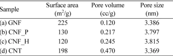
BET: The specific surface area, pore volume and size of the carbon nanomaterials were measured using BET, the results of which are shown in Table 4. The specific surface area of the carbon nanomaterials was estimated to be in the range of 120–225 m2/g.
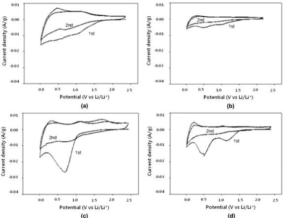
CV: Among the electrochemical characteristics of the carbon nanomaterials, cell reversibility was investigated via CV, the results of which are shown in Figs. 7 and 8. In CV, smaller potential energy difference between the peak that appears in the reduction process as lithium ions are being charged and the peak that appears from oxidation process as lithium ions are being discharged indicates greater revers- ibility.
The graphs shown in Figs. 7 and 8 represent results from using LiClO4 and LiPF6 as the electrolyte, respectively. In Fig. 7(a), the reduction peak that appeared during the first charging process was at 1 V, while the oxidation peak that appeared during the discharging process was at 1.1 V. Also in Fig. 7(a), the reduction peak that appeared during the sec- ond charging process was at 0.6 V, while the oxidation peak that appeared during the discharging process was at 0.5 V.
In Fig. 7(d), the reduction peaks during the first charging process appeared at 1.1 and 0.5 V, while oxidation peaks during the discharging process appeared at 0.2 and 1.1 V.
Also in Fig. 7(d), the reduction peak that appeared during the second charging process was at 0.8 V, while the oxidation peaks that appeared during the discharging process was at 0.2 and 1.1 V.
The results shown in Fig. 7(a) and (d), which represented results from using LiClO4 as the electrolyte, appeared as being relatively more reversible than the results from using LiPF6, which indicated that for these carbon nanomaterials, using LiClO4 as the electrolyte can allow superior reversibility to be achieved than from using LiPF6.
Galvanostatic charge-discharge method: For examination of the electrochemical characteristics of the carbon nano- materials, cycle performance experiment was performed to investigate their charge-discharge capacity. The exper- imental conditions were same as CV, i.e. a voltage range Figure 5. X-ray diffraction patterns of GNF, CNF_P, CNF_H
and MWCNT.
Figure 6. XPS spectra of (a) GNF, (b) CNF_P, (c) CNF_H, (d) MWCNT.
Table 3. XPS results of GNF, CNF_P, CNF_H and MWCNT Name Peak BE (eV) Range Analysis C1s Scan A 284.20 ~ 284.78 C-C combination C1s Scan B 285.94 ~ 286.61 C-O combination C1s Scan C 287.61 ~ 289.67 C=O combination C1s Scan D 287.52 ~ 290.62 COO combination
Table 4. BET results of (a) GNF, (b) CNF_P, (c) CNF_H, (d) MWCNT Sample Surface area
(m2/g)
Pore volume (cc/g)
Pore size (nm)
(a) GNF 225 0.120 3.386
(b) CNF_P 130 0.217 3.797
(c) CNF_H 120 0.245 3.815
(d) CNT 198 0.470 3.369
Figure 7. Cyclic voltammograms (LiClO4) of (a) GNF, (b) CNF_P, (c) CNF_H, (d) MWCNT.
Figure 8. Cyclic voltammograms (LiPF6) of (a) GNF, (b) CNF_P, (c) CNF_H, (d) MWCNT.
of 0.01–2 V (vs Li/Li+) with current density of 100 mA/g were applied, and the measurements were taken from 30 cycles.
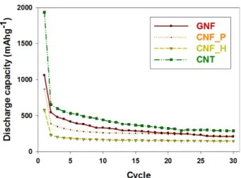
Figures 9 and 10 show the measured results from using LiClO4 and LiPF6 as the electrolyte, respectively, and the data derived is presented in Tables 5 and 6. The retention rate of discharge capacity was calculated by using discharge capacity after 30 cycles/maximum discharge capacity×100.
Among the cases that used LiClO4 as the electrolyte, MWCNT showed the highest initial discharge capacity of 1,935 mAh/g, and a discharge capacity after 30 cycles of 290 mAh/g, which was equivalent to a retention rate of 15.0%.
Among the cases that used LiClO4 as the electrolyte, the highest discharge capacity retention rate in Table 5 was shown by CNF_P with initial discharge capacity of 868 mAh/g and discharge capacity after 30 cycles of 224 mAh/g, which was equivalent to a retention rate of 25.8%.
Nano-carbon/Si composite
SEM: Fig. 11 shows the SEM results of prepared nano-car- bon/Si composites: silicon-graphite nanofiber_antler (Si/
GNF), silicon-carbon nanofiber_platelet (Si/CNF_P), sili- con-carbon nanofiber_herringbone (Si/CNF_H), and sili- con-carbon nanotube_multi-wall (Si/MWCNT). As shown in Fig. 11, when the SEM results of four types of nano-car- bon/Si composites were compared, Si particles showed diameters < 1 µm after the powder was ball milled. In Fig. 11, the carbon nanomaterial in Si/GNF showed a form that had a diameter of approximately 200 nm, while those in Si/CNF_P, Si/CNF_H, and Si/MWCNT showed similar SEM results with their diameter ranging between 40 and 80 nm.
EDS: EDS spectra were measured for qualitative and quantitative analyses of the specific areas of the nano-car- bon/Si composites, the results of which are shown in Table 7.
Figure 9. Cycle performances (LiClO4) of GNF, CNF_P, CNF_H and MWCNT.
Figure 10. Cycle performances (LiPF6) of GNF, CNF_P, CNF_H and MWCNT.
Table 5. Cycle performance data (LiClO4) of (a) GNF, (b) CNF_P, (c) CNF_H, (d) MWCNT
Sample (Electrolyte : LiClO4)
Discharge capacity (mAh/g) Retention rate Max After 30 cycles (%)
(a) GNF 1,059 207 19.5
(b) CNF_P 868 224 25.8
(c) CNF_H 578 146 25.2
(d) MWCNT 1,935 290 15.0
Table 6. Cycle performance data (LiPF6) of (a) GNF, (b) CNF_P, (c) CNF_H, (d) MWCNT
Sample (Electrolyte:
LiPF6)
Discharge capacity (mAh/g) Retention rate Max After 30 cycles (%)
(a) GNF 455 16 2.86
(b) CNF_P 1,065 66 6.20
(c) CNF_H 1,327 12 0.90
(d) MWCNT 1,643 74 4.50
Figure 11. SEM images of (a) Si/GNF, (b) Si/CNF_P, (c) Si/
CNF_H, (d) Si/MWCNT.
In Table 7, the mean value of carbon element in Si/GNF, Si/CNF_P, Si/CNF_H, and Si/MWCNT is 81.8%, 78.3%, 83.2%, and 82.8%, respectively. Further, the mean value of Si element in Si/GNF, Si/CNF_P, Si/CNF_H, and Si/
MWCNT was 11.3%, 17%, 11.4%, and 11.3%, respectively.
Thus, the content of Si was distinctly lower that the percent- age of carbon present in the samples.
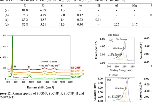
Raman spectroscopy: Raman spectra were measured to compare the crystallinity of carbon and Si in the prepared nano-carbon/Si composites, the results of which are shown in Fig. 12. As shown in Fig. 12, Si-specific peaks that did not appear in the Raman spectra of carbon nanomaterials appeared near 510 and 930 cm−1. These Si-specific peaks exhibited narrower and higher intensity, which indicated that Si had better crystallinity than carbon. Table 8 shows the calculated values of D/G ratios for nano-carbon/Si com- posites based on the Raman results. In Si/GNF, Si/CNF_P, Si/CNF_H, and Si/MWCNT, D/G ratio value is 1.0238, 1.3413, 1.1911, and 1.0670, respectively, which indicated
that Si/GNF had the lowest D/G ratio value among the nano- carbon/Si composites, meaning it had the best crystallinity.
In comparison, MWCNT among the carbon nanomaterials showed the best crystallinity (see Table 2).
Table 7. EDS results of (a) Si/GNF, (b) Si/CNF_P, (c) Si/CNF_H, (d) Si/MWCNT (atomic %)
C O Si Fe Ni Al Mg Ca Ti
(a) 81.8 6.89 11.3 - - - - - -
(b) 78.3 4.49 17.0 0.12 - - - 0.14 -
(c) 83.2 4.87 11.4 0.22 0.11 - - - 0.14
(d) 82.8 5.21 11.3 0.30 - 0.25 0.17 - -
Figure 12. Raman spectra of Si/GNF, Si/CNF_P, Si/CNF_H and Si/MWCNT.
Table 8. Raman spectroscopy D/G ratio of (a) Si/GNF, (b) Si/
CNF_P, (c) Si/CNF_H, (d) Si/MWCNT
Sample D/G ratio
(a) Si/GNF 1.0238
(b) Si/CNF_P 1.3413
(c) Si/CNF_H 1.1911
(d) Si/MWCNT 1.0670
Figure 13. XPS spectra (Carbon) of (a) Si/GNF, (b) Si/CNF_P, (c) Si/CNF_H, (d) Si/MWCNT.
Figure 14. XPS spectra (Silicon) of (a) Si/GNF, (b) Si/CNF_P, (c) Si/CNF_H, (d) Si/MWCNT.
XPS: To investigate carbon bond energy of carbon and Si in the prepared nano-carbon/Si composites, XPS spec- tra were measured. Measured results are shown in Figs.
13 and 14 and analyzed results are shown in Table 9.
In looking at the carbon nanomaterials mentioned ear- lier, carbon bond energy showed C-C, C-O, C=O, and COO bones. The figures show that Si bond energy was found at 100.26–100.61eV for Si-C bond and at 104.07–104.75eV for SiO2 bond. Here, it is believed that the Si-C bond rep- resents a bond formed during the process of coating the pyrolytic carbon onto Si.
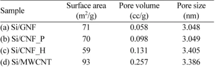
BET: The specific surface area and pore volume and size of the prepared nano-carbon/Si composites were mea- sured using BET, the results of which are shown in Table 10.
The specific surface areas of the four types of nano-carbon/Si composites were estimated as 59–93 m2/g. Compared to the BET results of the carbon nanomaterials, specific surface area of the nano-carbon/Si composites showed lower values.
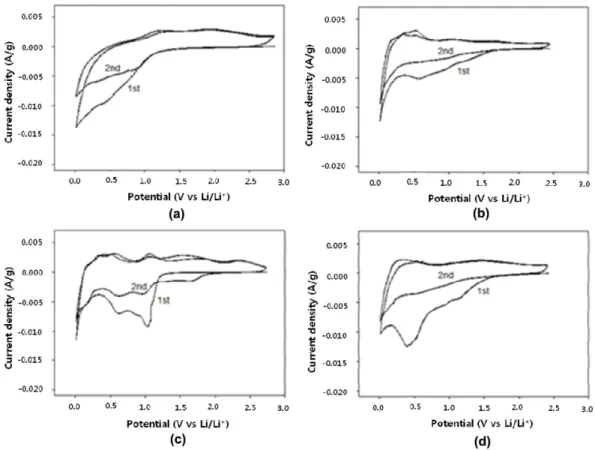
Cycle voltammetry: Among the electrochemical char- acteristics of the prepared nano-carbon/Si composites, cell reversibility was investigated via CV, the results of which are shown in Figs. 15 and 16. The experiment was per- formed under the same conditions as the carbon nanoma- terial experiment, voltage range of 0.01–2 V (vs Li/Li+) with current density of 100 mA/g being applied. The graphs shown in Figs. 15 and 16 represent results from using LiClO4 and LiPF6 as the electrolyte, respectively.
Relatively greater reversibility was found in Figs. 15(b) and (c), which used LiClO4 as the electrolyte. In Fig. 15(b), the Table 9. XPS results (Carbon, Silicon) of Si/GNF, Si/CNF_P, Si/
CNF_H and Si/MWCNT
Name Peak BE (eV) Range Analysis C1s Scan A 284.66 ~ 284.94 C-C combination C1s Scan B 285.37 ~ 286.29 C-O combination C1s Scan C 286.83 ~ 288.09 C=O combination C1s Scan D 290.26 ~ 290.61 COO combination Si2p Scan A 100.26 ~ 100.61 Si-C combination Si2p Scan B 104.07 ~ 104.75 SiO2 combination
Table 10. BET results of (a) Si/GNF, (b) Si/CNF_P, (c) Si/CNF_H, (d) Si/MWCNT
Sample Surface area (m2/g)
Pore volume (cc/g)
Pore size (nm)
(a) Si/GNF 71 0.058 3.048
(b) Si/CNF_P 70 0.098 3.049
(c) Si/CNF_H 59 0.131 3.405
(d) Si/MWCNT 93 0.257 3.386
Figure 15. Cyclic voltammograms (LiClO4) of (a) Si/GNF, (b) Si/CNF_P, (c) Si/CNF_H, (d) Si/MWCNT.
reduction peaks that appeared during the first charging process were at 1.1 and 0.5V, while the oxidation peaks that appeared during the discharging process were at 0.5 and 1 V.
Also in Fig. 15(b), the reduction peak that appeared during the second charging process was at 0.8 V, while the oxidation peaks that appeared during the discharging process were at 0.5 and 1 V. In Fig. 15(c), the reduction peaks that appeared during the first charging process were at 1.3 and 0.5V, while the oxidation peaks that appeared during the discharging process were at 0.5 and 1.1 V. Also in Fig. 15(c), the reduction peak that appeared during the second charging process was at 0.8 V, while the oxidation peaks that appeared during the discharging process were at 0.5 and 1.1 V. CV results on the nano-carbon/Si composites showed that Fig. 15(b) and (c), which used LiClO4 as the electrolyte, had greater reversibility, which indicated that just as in the carbon nanomaterials, better reversibility was achieved in the nano-carbon/Si com- posites when LiClO4 was used as the electrolyte, as opposed to using LiPF6.
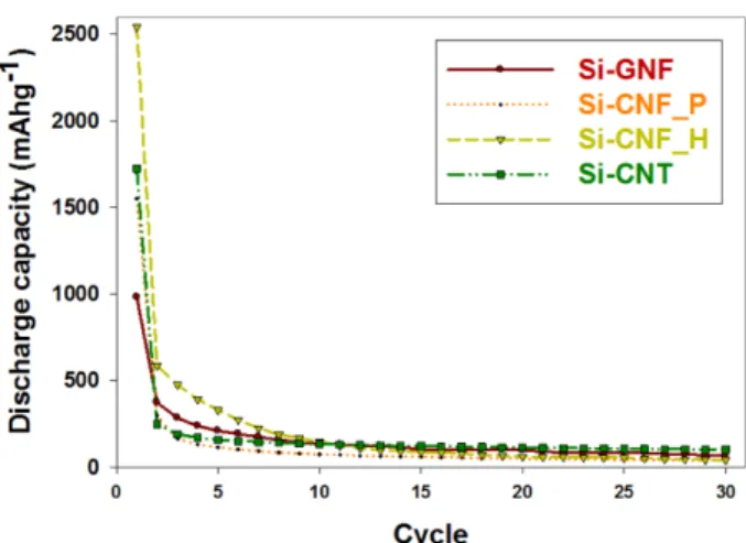
Galvanostatic charge-discharge method: For examina- tion of the electrochemical characteristics of the prepared carbon/Si composites, cycle performance experiment was performed to investigate their charge-discharge capacity,
the results of which are shown in Figs. 17 and 18. The exper- imental conditions were same as in the carbon nanoma- terial experiment, i.e. voltage range of 0.01–2 V (vs Li/Li+) with current density of 100 mA/g being applied, and the measurements were taken from 30 cycles of charge/discharge.
Figs. 17 and 18 show the measured results from using LiClO4 Figure 16. Cyclic voltammograms (LiPF6) of (a) Si/GNF, (b) Si/CNF_P, (c) Si/CNF_H, (d) Si/MWCNT.
Figure 17. Cycle performances (LiClO4) of Si/GNF, Si/CNF_P, Si/CNF_H and Si/MWCNT.
and LiPF6 as the electrolyte, respectively, and the results are also shown in Tables 11 and 12.
As shown in Table 11, (b) Si/CNF_P showed the high- est initial discharge capacity of 1,788 mAh/g, and the dis- charge capacity after 30 cycles was 38 mAh/g, which was equivalent to a retention rate of 2.13%. Highest discharge retention rate in Table 11 was found for (a) Si/GNF with initial discharge capacity of 1,388 mAh/g and discharge capacity after 30 cycles of 73 mAh/g, which was equivalent to a retention rate of 5.26%. In comparison to the cycle per- formance of carbon nanomaterials that used the same electro- lyte of LiClO4, the carbon/Si composites showed mostly higher initial discharge capacity, but discharge capacity retention rates were very low overall as compared to the carbon nanomaterials. In Table 12, which shows the results
from using LiPF6 as the electrolyte, (c) Si/CNF_H had the highest initial discharge capacity of 2,540 mAh/g, followed by 42 mAh/g after 30 cycles, which was equivalent to dis- charge capacity retention rate of 1.65%. Also in Table 12, (a) Si/GNF showed the highest discharge capacity reten- tion rate of 7.03% with discharge capacity of 981 mAh/g initially and 69 mAh/g after 30 cycles. Compared to the cycle performance of carbon nanomaterials that used the same electrolyte of LiPF6, the carbon/Si composites, in over- all, showed higher initial discharge capacity and also an over- all increase in discharge capacity retention rate. As shown in Tables 11 and 12, among the nano-carbon/Si composites, (c) Si/CNF_H which used LiPF6 as the electrolyte had the highest initial discharge capacity, while Si/GNF which also used LiPF6 as the electrolyte had the highest discharge capac- ity retention rate. Compared to the cycles of the carbon nano- materials, the nano-carbon/Si composites showed mostly higher initial discharge capacity when using LiClO4 and LiPF6 as the electrolyte.
CONCLUSIONS
In the present study, different types of carbon nanoma- terials and nano-carbon/Si composites, prepared via CVD, and their physiochemical and electrochemical character- istics were investigated.
(1) SEM measurement results showed that GNF had a diameter of approximately 260 nm, while CNF_P, CNF_H, and MWCNT had diameters of approximately 40–80 nm.
In comparison, Si appeared in various forms with diameter
<1 µm after ball milling.
(2) EDS analysis results showed that the mean value of carbon element was 82.3–94.8% in the carbon nanomateri- als and 78.3–83.2% in the nano-carbon/Si composites. In the nano-carbon/Si composites, the mean value of Si element was 11.3–17%.
(3) Raman analysis results showed that the best crystallinity was found in the carbon material MWCNT, which showed D/G ratio of 0.8842.
(4) In the XRD analysis results, both the carbon nano- materials and nano-carbon/Si composites showed distinct peaks characteristic of crystalline structure of graphite at 2θ = 26° and 46°. Moreover, all four types of nano-carbon/
Si composites clearly showed peaks with narrow and high intensity that are specific to Si crystalline structure.
(5) In the XPS results, all of the peaks for carbon bond energy appeared in similar location for the carbon nano- materials and nano-carbon/Si composites, while the Si-C bond also appeared at 100.26–100.61eV in the carbon/Si Figure 18. Cycle performances (LiPF6) of Si/GNF, Si/CNF_P,
Si/CNF_H and Si/MWCNT.
Table 11. Cycle performance data (LiClO4) of (a) Si/GNF, (b) Si/
CNF_P, (c) Si/CNF_H, (d) Si/MWCNT Sample (Electrolyte :
LiClO4)
Discharge capacity (mAh/g) Retention rate Max After 30cycles (%)
(a) Si/GNF 1,388 73 5.26
(b) Si/CNF_P 1,788 38 2.13
(c) Si/CNF_H 1,547 31 2.00
(d) Si/MWCNT 1,501 46 3.06
Table 12. Cycle performance data (LiPF6) of (a) Si/GNF, (b) Si/
CNF_P, (c) Si/CNF_H, (d) Si/MWCNT Sample (
Electrolyte : LiPF6)
Discharge capacity (mAh/g) Retention rate Max After 30cycles (%)
(a) Si/GNF 981 69 7.03
(b) Si/CNF_P 1,549 38 2.45
(c) Si/CNF_H 2,540 42 1.65
(d) Si/MWCNT 1,722 102 5.92
composites.
(6) BET results showed that the values of specific sur- face area for the carbon nanomaterials and carbon/Si com- posites were in the range of 120–225 m2/g and 59–93 m2/g, respectively, indicating that the specific surface area values of the carbon nanomaterials were generally higher than those of the nano-carbon/Si composites.
(7) In the CV analysis results, using LiClO4 as the electrolyte, as compared to using LiPF6, resulted in better reversibility for both the carbon nanomaterials and nano-carbon/Si compos- ites.
(8) In the charge/discharge experiments using two types of electrolytes, LiClO4 and LiPF6, most of the nano-carbon/Si composites showed initial discharge capacity values that were higher than the initial discharge capacity values of the carbon nanomaterials.
(9) The highest initial discharge capacity (2,540 mAh/g) was seen in Si/CNF_H, which used LiPF6 as the electrolyte.
The discharge capacity value after 30 cycles was 42 mAh/g, showing discharge capacity retention rate of 1.65%. The highest discharge capacity retention rate was seen in CNF_P, which used LiClO4 as the electrolyte. The initial discharge capacity value was 868 mAh/g, and the discharge capacity value after 30 cycles was 224 mAh/g, which was equivalent to discharge capacity retention rate of 25.8%.
Acknowledgments. This research was financially supported by the Ministry of Education, Science Technology (MEST) and National Research Foundation of Korea (NRF) through the Human Resource Training Project for Regional Inno- vation (NO.2015035858).
REFERENCES
1. Wakihara, M. Mater. Sci. Eng. R-Rep. 2001, 33, 109.
2. Yamauchi, Y.; Hino, T.; Ohzeki, K.; Kubota, Y.; Deyama, S. Carbon 2005, 43, 1334.
3. Kim, D. W. Prospectives of Industrial Chemistry 2004, 7, 1.
4. Ding, N.; Xu, J.; Yao, Y.; Wegner, G.; Lieberwirth, I.; Chen, C. J. Power Sources 2009, 192, 644.
5. Zhang, J.; Xie, Z.; Li, W.; Dong, S.; Qu, M. Carbon 2014, 74, 153.
6. Prosini, P. P.; Cento, C.; Alessandrini, F.; Gislon, P.; Mancini, A.; Rufoloni, A.; Rondino, F.; Santoni, A. Solid State Ion.
2014, 260, 49.
7. Jang, S. M.; Miyawaki, J.; Tsuji, M.; Mochida, I.; Yoon, S. H. Carbon 2009, 47, 3383.
8. Chouvin, J.; Branci, C.; Saradin, J.; Oliver-Fourcade, J.;
Jumas, J. C.; Simon, B.; Biensan, Ph. J. Power Sources 1999, 81, 277.
9. Zhang, F.; Wang, K. X.; Li, G. D.; Chen, J. S. Electrochem.
Commun. 2009, 11, 130.
10. Shi, D. Q.; Tu, J. P.; Yuan, Y. F.; Wu, H. M.; Li, Y.; Zhao, X. B. Electrochem. Commun. 2006, 8, 1610.
11. Brumbarov, J.; Kunze-Liebhäuser, J. J. Power Sources 2014, 258, 129.
12. Hanai, K.; Liu, Y.; Imanishi, N.; Hirano, A.; Matsumura, M.; Ichikawa, T. J. Power Sources 2005, 146, 156.
13. Endo, M.; Kim, C.; Nishimura, K.; Fujino, T.; Miyashita, K. Carbon 2000, 38, 183.
14. Wang, H.; Ikeda, T.; Fukuda, K.; Yoshio, M. J. Power Sources 1999, 83, 141.
15. Flandriois, S.; Simon, B. Carbon 1999, 37, 165.
16. Villevieille, C.; Van Thournout, M.; Scoyer, J.; Tessier, C.;
Olivier-Fourcade, J.; Jumas, J. C.; Monconduit, L. Electrochim.
Acta 2010, 55, 7080.
17. Kasavajjula, U.; Wang, C.; Appleby, A. J. J. Power Sources 2007, 163, 1003.
18. Qrins. Home Page. http://www.qrins.com (Mar 30th 2016 search).