Electrochemical Response of Polymer Actuators using Finite Element Formulation and ANSYS/Emag
Sung-Soo Kang†
(Received March 28, 2010; Revised May 18, 2010; Accepted May 18, 2010)
Abstract:The two-dimensional finite element formulation for the basic field equations governing electrochemical responses of ionic conducting polymer-metal composite(IPMC) actuators is proposed in the present study. Biaxial deformation of a platinum plated Nafion actuator having 4 electrodes is dominated by electro-osmosis of hydrated ions and self-diffusion of free water molecules. Some numerical studies for IPMC actuators with electric field are carried out in order to show the validity of the proposed formulation and electric field analysis for the initial condition of total charge distribution are conducted using commercial code ANSYS/Emag.
Key words:Computational mechanics, Bio-materials, Finite element formulation, Polymer, Electrochemical analysis, Actuator
†Corresponding Author (Dept. of Mechanical and Automotive Engineering, Jeonju University, E-mail:[email protected], Tel: 063-220-3077)
1. Introduction
Ionic polymer-metal composites (IPMC) are biomimetic actuators and soft sensors with potential applications and shows large deflection, fast, yet soft actuation, and a very good durability. For these reasons, much attention has been focused on IPMC as a biomaterial for artificial muscles, as an intelligent material for robotics and MEMS. The bending motion of an ionic conducting polymer gel film with Pt electrodes was first found by Oguro et al. [1], 1992. Since then, the electrochemical and mechanical responses of IPMC have been theoretically and experimentally studied by many researchers.
Shahinpoor [2] presented a number of models for micro-electromechanics of
IPMC as electrically controllable artificial muscles and Nemat-Nasser et al. [3]
developed a micromechanical model which accounts for the coupled ion transport, electric field, and elastic deformation to predict the response of IPMCs.
Tadokoro et al. [4] proposed a white- box actuator model on the basis of physicochemical hypotheses, in which travel of sodium ions and water molecules in the actuator membrane is assumed to generate eigenstrains causing the deformation of IPMC. The bending deformation of the IPMC (a platinum plated Nafion) upon low electric field across its thickness is dominated by internal water redistribution [4], which is associated with electro- osmosis of hydrated ions and self-diffusion
of free water molecules. Two phenomena can be considered separately in the way that fast electro-osmosis is followed by much slower self-diffusion. Consequently, there is strain distribution(swelling and contraction) due to different water content throughout the thickness. The two-dimensional basic equations governing the electrochemical behavior of IPMC are approximated discretely by the finite element formulation based on Galerkin method [5]. For the accuracy of initial condition of a platinum plated Nafion actuator having 4 electrodes, the electric field analysis are conducted using commercial code ANSYS/Emag.
2. Two-dimensional FE Formulation for Electrochemical Response
Figure 1 shows the free body diagram of hydrated Na+, by deformation of polymer actuators with two processes, electro- osmosis of hydrated ions to the cathode side and self-diffusion of water molecules to the anode side.
The first process is the forward motion in which the beam bends toward the anode side in a short time due to the sudden movement of hydrated cation to the cathode side. The second process is the backward motion in which the bending deformation is slowly recovered by the diffusion of free water molecules to the anode side. When a Nafion membrane is under an electric field, hydrated cations are subjected to the electric force to the cathode side. Hydrated cations are also subjected to viscous resistance force and diffusion force in the anode direction.
Based on the balance of these forces, the total charge Q(x,y,t) is expressed as follows [4].
ξ ξ ξ η η
η η
y d x
,y,t ,y,t Q eE y d
x ,t x, ,t Q x, eE
y x,y,t kT Q x
x,y,t kT Q t x,y,t Q
x y
∂
∂
− ∂
∂
∂
− ∂
∂ + ∂
∂
= ∂
∂
∂
∫
∫
( ) ( ) ( ) ( )) ( ) ( ) (
2 0
2 0
2 2 2
2 1
(1) where i is the electric current.
Figure 1: Free body diagram for hydrated Na+
Table 1 shows the material parameters and calculation conditions for Eq. (1).
Table 1: Material parameters and calculation conditions for forward motion
Coefficient of viscosity for
hydrated Na+ 1.18 10 [N s/m ]
2 -11
1= × ⋅
η
Boltzman constant k=1.380×10⁻²³[N⋅m/K]
Absolute temperature T=293[K]
Elemental charge e=1.6×10⁻¹⁹[C]
Dielectric constant of
hydrated Nafion membrane 2.8 10 [C/Nm ]
2 2 -3
e= × ⋅
ε
Time interval t=5×10⁻⁴[s]
Space interval h=2[μm]
Cross section area S=34.2×10⁻⁶[m2] Avogadro number Na=6.02×10⁻²³[/mol]
The charge concentration is calculated from the total charge.
ξ η η ξ td d c
eS N t y x
Q( , ,)= a
∫ ∫
0 0x y ( , ,) (2)where the initial condition : ]
mol/m [ 1147 y,0)
c(x, 3
0= =
c
The finite element formulation is conducted for Eq. (1) and Eq. (2). The total charge Q(x,y,t) is assumed to be a linear interpolation function of the elemental coordinate in each four-node rectangular element as follows.
[ ]
{ }
[ ]
( )( )
( )( )
( )( )
( )( )
{ }
⎪⎪
⎭
⎪⎪
⎬
⎫
⎪⎪
⎩
⎪⎪
⎨
⎧
=
⎥⎥
⎥⎥
⎦
⎤
⎢⎢
⎢⎢
⎣
⎡
− +
−
− +
− + +
=
⎥⎥
⎥⎥
⎦
⎤
⎢⎢
⎢⎢
⎣
⎡
=
=
l k j i e
l l
k k
j j
i i T
T
e
Q Q Q Q Q y x
y x
y x
y x
N N N N N
t Q y x N t y x Q
) ( 41
4 3 2 1
) (
, 1 1
1 1
1 1
1 1
, ) ( ) , ( ) , , (
(3)
where N( yx, )is shape functions and Qi,j,k,l are the nodal total charges. The following equation is obtained by the finite element formulation [5].
{ } { }
{ }
{ ( ) ( 0)} ( ) 0
) ) (
0 ( ) (
) ) (
) ( ) (
(
) ( ) ( ) ] (
[
2 0
2 0
0 0
2 2 2
2 1
T
⎟⎟ =
⎠
⎞
∂
∂
− ∂ +
∂
∂
− ∂ +
∂ + ∂
∂ + ∂
⎜⎜⎝
⎛
∂
− ∂
∂
− ∂
∂
∂
∫
∫
∫
∫
∫∫
dxdy y d
x ,y,t ,y, Q
Q ,y,t S Q ε
e
y d x
,t x, , Q x, Q ,t x, S Q ε
e
y x,y,t dτ Q τ S i ε
e x x,y,t dτ Q τ S i ε
e
y x,y,t kT Q x
x,y,t kT Q t x,y,t N Q
x e
y e
t y e t
x e
ξ ξ ξ
ξ
η η η
η η
(4)
Substituting Eq. (3) into Eq. (4), the following ordinary differential equation is obtained.
[ ]
A(e){Q•(e)}+[ ]
B(e){Q(e)}=0 (5)[ ]
A(e) =∫∫
[N]T[N]dxdy[ ]
( )
{
i τdτ} {
Nx i τ dτ}
Ny dxdyS N ε e
Y X S X ε e
y dxdy N y N x N x N B kT
t y t
x e
e
T e T
∫∫ ∫ ∫
∫∫
⎥⎦
⎢ ⎤
⎣
⎡
∂ + ∂
∂ + ∂
× + +
⎭⎬
⎫
⎩⎨
⎧
∂
∂
∂ +∂
∂
∂
∂
= ∂
] ) [ ] ( ) [ ( ] [
] [ ] [ ] [
] [ ] [ ] [ ] [
0 0
T 1
2 1 1
1 ) (
η η
η
d dxdy
y x
,y,t Q N
,y, Q ,y,t Q N N X
dxdy y d
x ,t x, Q N
, x, Q ,t x, Q N N X
x y
⎟⎟⎠
⎞
∂
∂
×∂
⎜⎝
⎛ −
=
⎟⎟⎠
⎞
∂
∂
×∂
⎜⎝
⎛ −
=
∫∫ ∫
∫∫ ∫
ξ ξ ξ ξ
η η η η
} ) ( ]{
[
} ) 0 ( ) ( ]{
[ ] [ ] [
} ) ( ]{
[
} ) 0 ( ) ( ]{
[ ] [ ] [
2 0 T 2
2 0 T 1
[ ]
[
1 1 1 1]
) 0 ( ) (
) 0 ( ) (
) 0 ( ) (
) 0 ( ) (
41 − −
×
⎪⎪
⎭
⎪⎪
⎬
⎫
⎪⎪
⎩
⎪⎪
⎨
⎧
−
−
−
−
=
x,y, Q x,y,t Q
x,y, Q x,y,t Q
x,y, Q x,y,t Q
x,y, Q x,y,t Q Y
l l
k k
j j
i i
The following equation is obtained by the finite element formulation [5] for Eq. (2).
0 ) ) (
] (
[ T 2 ⎟⎟ =
⎠
⎜⎜ ⎞
⎝
⎛ −
∂
∂
∫∫
N ∂Qxx,y,ty NaeScx,y,t dxdy (6)The substitution of Eq. (3) into Eq. (6) leads to the following form of equation.
[ ]
C(e){c(e)}=[ ]
D(e){Q(e)} (7)[ ] [ ] ∫∫
∫∫
∂
∂
∂
= ∂
=
y dxdy N x D N
dxdy N N eS N C
e T
T a e
] [ ] [
, ] [ ] [
) (
) (
The concentration of water molecules )
, ( tx
w is calculated by the following equation [4].
⎭⎬
⎫
⎩⎨
⎧
∂ +∂
∂
= ∂
∂
∂
2 2 2 2 2
) , , ( ) , , ( )
, , (
y t y x w x
t y x w kT t
t y x w
η (8)
where the initial condition : )
, , ( )
0
(x,y, w1 w2 ncx yt1
w = + +
Table 2 shows the material parameters and calculation conditions for the backward motion.
Table 2: Material parameters and calculation conditions for backward motion
Concentration of bound water to the fixed SO-3 groups
] mol/m [ 381
4 3
1= w
Concentration of free
water molecules 4381[mol/m]
3 2=
w Time of ending of forward motion and beginning of backward motion
[s]
1=0.11 t
Hydration number of Na+ ions in swollen Nafion
7 .
=4 n
Coefficient of viscosity
for free water molecules 11.6 10 [N s/m]
2 -11
2= × ⋅
η
Time interval t=5×10⁻³[s]
The finite element formulation for Eq.
(8) leads to the following equation.
) 0 , , (
) , , ( ) , , ] (
[ 2 2 2 2
2
=
⎟⎠
⎞
∂
−∂
⎜⎜⎝
⎛
⎭⎬
⎫
⎩⎨
⎧
∂ +∂
∂
∫∫
∂t dxdy t y x w
y t y x w x
t y x w NT kT
η
(9)
Assuming interpolation function for )
, ( tx
w , the following form of equation is obtained from Eq. (9).
[ ]
A(e){w•(e)}+[ ]
E(e){w(e)}=0 (10)[ ]
A(e) =∫∫
[N]T[N]dxdy[ ]
Ee =∫∫
kT⎩⎨⎧∂[∂Nx]T∂∂[Nx]+∂[∂Ny]T ∂∂[Ny]⎭⎬⎫dxdy2 ) (
η
Eqs. (5) and (10) are numerically integrated by using simple Euler scheme with time intervals given in Tables 1 and 2.
3. Numerical Results
3.1 Finite Element Analysis
The electrochemical response of the
IPMC beam has been analyzed under the voltage condition of 1V in the x, y direction, respectively. The charge concentration distribution in the Nafion membrane is shown in Figure 2. The charge concentration gradually decreases at the anode side and increases at the cathode side. Figure 3 shows the water concentration distribution. The water concentration increases near the anode side and decreases near the cathode side, because the diffusion of water molecule occurs from the cathode to the anode side where the water concentration is relatively low.
Figure 2: Charge concentration
Figure 3: Water concentration
The calculated electrochemical solutions for the case of unidirectional voltage have agreed well with the one-dimensional finite element solution[6].
3.2 ANSYS/Emag Analysis
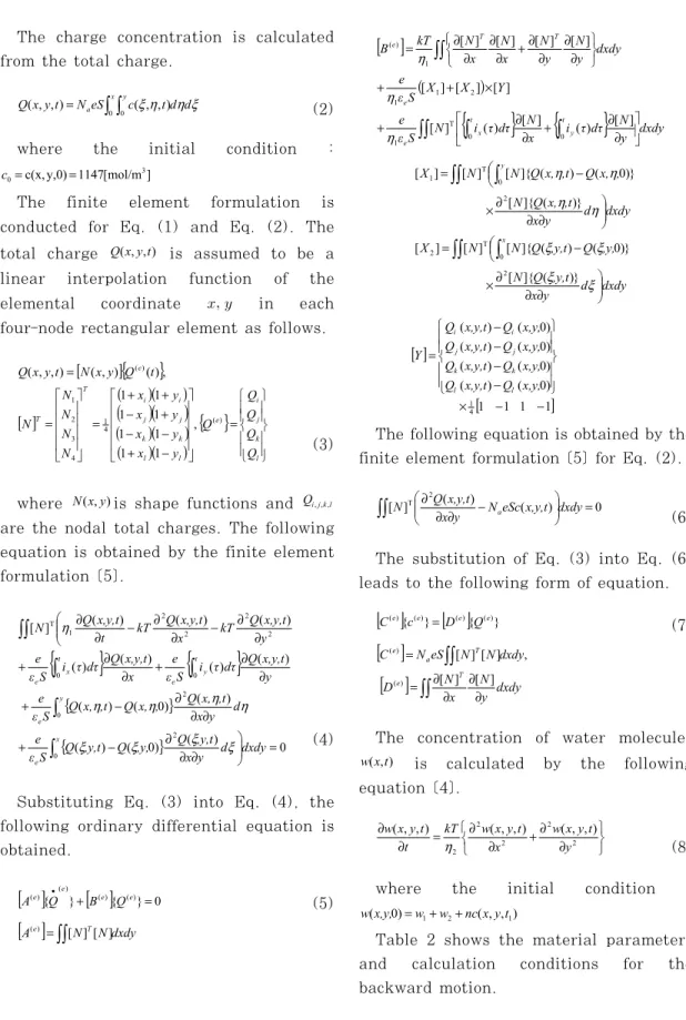
The electric field analysis for the quarter symmetry model which the dielectric material was inserted between electrodes is conducted. By this analysis, the charge on the electrode plates can be calculated. Figure 4 shows the concept for electric field analysis in ANSYS/Emag.
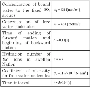
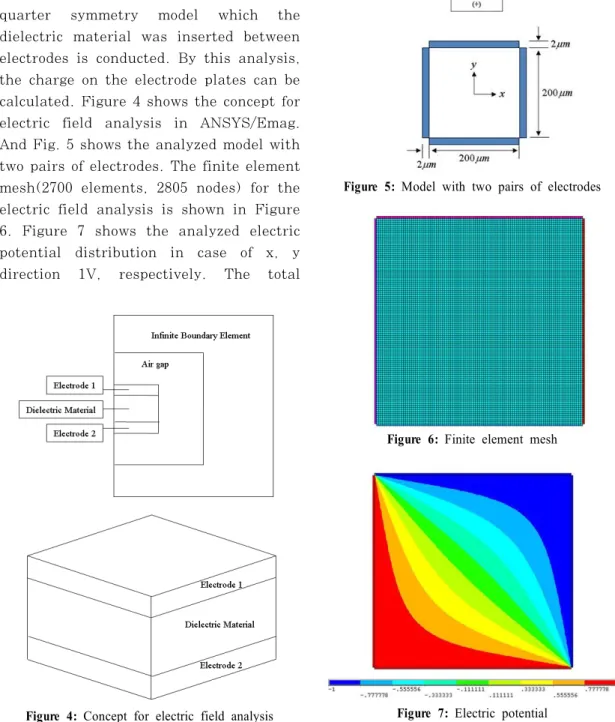
And Fig. 5 shows the analyzed model with two pairs of electrodes. The finite element mesh(2700 elements, 2805 nodes) for the electric field analysis is shown in Figure 6. Figure 7 shows the analyzed electric potential distribution in case of x, y direction 1V, respectively. The total
Figure 4: Concept for electric field analysis
Figure 5: Model with two pairs of electrodes
Figure 6: Finite element mesh
Figure 7: Electric potential
(a) Over the entire thickness
(b) Enlarged portion near anode side
(c) Enlarged portion near cathode side Figure 8: Total charge in diagonal direction
charge distribution in diagonal direction calculated for the forward motion are shown in Figure 8. The slope of the total charge in the Nafion membrane gradually decreases with time near the anode side and increases near the opposite, cathode side.
4. Conclusions
In the present study, two-dimensional finite element formulation is conducted for the basic field equations governing electrochemical response of polymer actuators with two pairs of electrodes upon applied electric field. The calculated electrochemical solutions have agreed well with the one-dimensional finite element solutions.
The two-dimensional electrochemical response for the case of bidirectional voltage were qualitatively reasonable. And by using the commercial code ANSYS/
Emag, the two-dimensional electric field analysis is conducted for the accuracy of initial condition of a platinum plated Nafion actuator having 4 electrodes.
Acknowledgment
This work was supported by the National Research Foundation of Korea Grant funded by the Korean Government (NRF-2009-0070236).
References
[1] K. Oguro, Y. Kawami and H.
Takenaka, “Bending of an ion- conducting polymer film-electrode composite by an electric stimulus at
low voltage”, Journal of Micromachine Society, vol. 5, no.1, pp.27-30, 1992.
[2] M. Shahinpoor, “Electromechanics of iono-electric beams as electrically controllable artificial muscles”, SPIE Conference on Electroactive Polymer Actuators and Devices, vol. 3669, no.
12, pp. 109-121, 1999.
[3] S. Nemat-Nasser, J. Y. Li, “Electrochemical response of ionic polymer-metal composites”, Journal of Applied Physics, vol. 87, no.7, pp. 3321-3331, 2000.
[4] S. Tadokoro, S. Yamagami, T.
Takamori and K. Oguro, “An actuator model of ICPF for robotic applications on the basis of physicochemical hypotheses”, Proc. Of the 2000 IEEE International Conference on Robotics and Automation(ICRA2000), vol. 2, pp.
1340-1346, 2000.
[5] K. J. Bathe, Finite Element Procedures, Prentice Hall, 1996.
[6] S. Kang, “Finite element modeling of electrochemical governing equations for ionic polymer actuators”, Journal of the Korean Society of Marine Engineering, vol. 32, no.5, pp. 759-767, 2008.
Author Profile
Sung-Soo Kang
Assistant Professor, Dept. of Mechanical and Automotive Eng. Jeonju Univ., Ph.
D in Environmental and Ocean Eng.
Univ. of Tokyo in 2003, M.S. in Environmental and Ocean Eng. Univ. of Tokyo in 2000, B.E. in Mechanical and Design Eng. Pusan National Univ. in 1998.