Characteristics of Si 3 N 4 Laser Assisted Machining according to the Laser Power and Feed Rate
Jong-Do Kim†․Su-Jin Lee 1 ․Jeong Suh 2
(Received May 31, 2010; Revised July 5, 2010; Accepted August 10, 2010)
Abstract: This study makes an estimate of the laser-assisted machining (LAM) of an economically viable process for manufacturing precision silicon nitride ceramic parts using a high-power diode laser (HPDL). The surface is locally heated by an intense laser source prior to material removal, and the resulting softening and damage of the workpiece surface simplify the machining of the ceramics. The most important advantage of LAM is its ability to produce much better workpiece surface quality compared to conventional machining. Also important are its larger material removal rates and longer tool life. The cutting force and surface temperature were measured on-line using a pyrometer and a dynamometer, respectively. Tool wear, chips and the surface of the workpiece were measured using optical microscopy, and the surface and fractured cross-section of Si 3 N 4 were measured by SEM. During the LAM process, the cutting force and tool wear were reduced and oxidation of the machined surface was increased according to the increase in the laser power. Moreover, the more the feed rate increased, the more the cutting force and tool wear increased.
Key words: LAM(laser assisted machining), Si 3 N 4 (silicon nitride), Laser power, Feed rate, YSiAlON
†Corresponding Author (Korea Maritime University, Division of Marine System Engineering, E-mail:[email protected], Tel: 051-410-4253)
1 Korea Maritime University
2 Korea Institute of Machinery & Materials
1. Introduction
Si 3 N 4 is known for its high strength, excellent wear resistance, chemical stabilityand maintenance of its high strength at high temperatures compared to its weight. Hence, it is receiving attention in various fields such as construction, engineering, aerospace and medical science. However, the sintering process necessary for obtaining high-strength and high-quality Si 3 N 4 ceramic reduces the measurement of the components and the precision of the shape; therefore, a finish
machining process is required to obtain precise Si 3 N 4 ceramic components.
However, the high strength and high
brittleness of Si 3 N 4 ceramic materials
cause difficulty in processing. As a process
for obtaining desired measurements,
diamond grinding is most widely used. The
diamond grinding method is advantageous
for obtaining materials with precise
measurements, but the rate of removal
and flexibility are low. Thus, this method
cannot be easily used for components of
Si 3 N 4 with complicated shapes. In
addition, problems such as the high processing cost and the occurrence of surface damage that lead to a reduction in the surface strength have been noted.
Therefore, the production of Si 3 N 4 products with excellent quality at a low cost can lead to enhanced utilization of Si 3 N 4 in various fields [1-6].
As such, research on an alternative processing method of reducing the restrictions on productivity and on the economic aspects of the Si 3 N 4 ceramic process is necessary. Accordingly, this study focused on the LAM of Si 3 N 4
ceramics that efficiently removes the material through machining of a zone softened by local heating. In particular, the focus of this study was on the effects of the laser power and the feed rate [7].
2. Experimental Materials and Methods
2.1 Experimental Material
In this study, engineering Si 3 N 4
composed of hexagon-shaped β-Si 3 N 4 and amorphous YSiAlON was compressively sintered at a high temperature and high pressure using the HIP (hot isostatic pressing) method to remove internal pores and defects before use. Silicon nitride generally shows lower bending strength at 900~1000℃ and is softened with reduced YSiAlON viscosity at 1000℃ or above. To make the machining process by lather easier, round bar-shaped workpieces with a length of 150mm and a diameter of 16mm were used.
A 2.5kW HPDL with a high performance-to-price ratio was used as the heat source in this study. The laser power was varied with a fixed rotational
N
Lℓ Laser head Laser head
Pyrometer
dVc
90°
180°
Chip
Main force Feed force
Thrust force
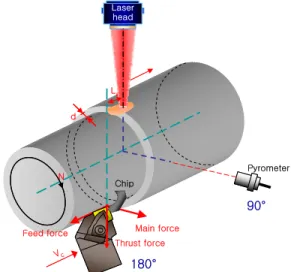
Figure 1: Schematic illustration of the laser assisted machining system
speed of 620rpm after fixing the workpieces on the chuck and performing the cutting process at the speed of 0.013mm/rev using suitable tools. A CBN (cubic boron nitride) insert with a nose radius of 0.8mm, a thickness of 4.76mm and a negative angle of inclination of -6°(CNMA 120408) was used as the cutting tool. In addition, a pyrometer and a dynamometer were installed to measure the temperature and cutting force on a real-time basis. An optical revolver module with a maximum spindle rotation of 4000rpm and maximum axial feed rates of 30, 16 and 30 m/min for each axis was installed on the Z-axis of the complex processing machine. A specially manufactured square beam with a size of 5× 5mm was used for the optical system.
2.2 Experimental Method
Figure 1 shows a schematic diagram of
the experimental device installed for
laser-assisted machining. The round
Magnificatio n Photo
×3,000 ×50,000
SEM ima g e
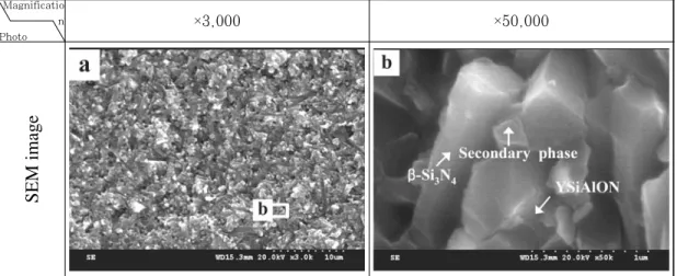
Figure 2: SEM image of HIP treated silicon nitride
bar-shaped workpieces were fixed to a three-jaw chuck, and the pyrometer was installed at 90°. The cutting tool and dynamometer were installed at 180° from the center of the laser to measure the workpiece temperature and cutting force on a real-time basis. A lead distance of nearly 2.3mm was allowed between the laser center and the tools for efficient cutting and to prevent tool damage caused by direct laser irradiation. The rotational speed of the workpieces was fixed at 620rpm and the laser power and feed rate were varied to observe changes in thesurface temperature, heat effect, cutting force and processing surface.
Chips were collected to analyze their length and shape using an optical microscope. The surface of the processed workpieces was observed through an optical microscope and SEM, and EDS was used to perform component analyses.
3. Results and Discussion
3.1 Mechanism of the LAM of Silicon Nitride
Sintered silicon nitride ceramic is most-
ly composed of hexagonal β-Si 3 N 4 mole-
cules and amorphous YSiAlON near
the grain boundary, as shown in the SEM
micrograph of the as-received
fractography of Si 3 N 4 with YSiAlON in
Figure 2. It is compressively sintered at a
high temperature and a high power. As a
high-strength characteristic, silicon
nitride materials cannot be processed by
PCBN tools in general at room
temperature. However, once the material
properties are changed by increasing the
surface temperature using a laser, PCBN
tools can be used for machining of this
material. As silicon nitride reacts with a
sintering material at 1000℃ or above and
softens with the reduced viscosity of
amorphous YSiAlON, plastic deformation
can occur and the removal of materials
becomes easier due to the crack in the
heat-affected parts. Transgranular
fracturing of β-Si 3 N 4 crystal mainly occurs
before the softening of YSiAlON and
intergranular fracturing mainly occurs at
a high temperature of 1000℃ or above due
to the plastic deformation of the softened
SEM image Photo image
Crack in 800W 800W
600W 400W
Power Image
SEM image Photo image
Crack in 800W 800W
600W 400W
Power Image
10㎛
10㎛
10㎛ 10㎛10㎛10㎛ 10㎛
A
10㎛
10㎛
A
2㎛
crack
crack
A
2㎛
2㎛
crack
crack
A
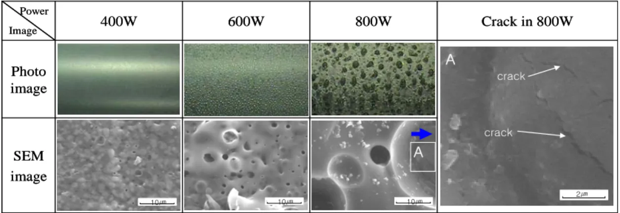
Figure 3: Photo and SEM image of surface preheated by laser power
YSiAlON. Silicon nitride can therefore be efficiently cut through machining at an increased temperature and low viscosity.
The tool life can also be increased [3,8].
3.2 Characteristics of LAM according to the Laser Power
In order to observe the preheating characteristics of a workpiece surface according to power changes when the workpieces are rotated at 620rpm and machined at a feed rate of 0.013mm/rev, the power was varied at 400W, 600W and 800W for observation. The temperature of the workpiece surface was maintained at 1,270℃, 1,480℃ and 1,600℃ Figure 3 shows an actual-size photograph and SEM image of the workpiece surface and a SEM image of a crack in the surface that resulted at 800W. As shown in the SEM image, a laser power of 400W led to minute pores, suggesting formation of N 2
gas.
The workpiece surface began to swell at 600W, and such phenomena occurred more strongly at 800W with the observation of cracks under traces of N 2 gas. Figure 4 shows the result of an EDS analysis of
the surface of workpieces as received and after preheating. As shown in the figure, N element was detected before preheating but not after preheating. This suggests that processing at a certain temperature or above causes the N element to combine as N 2 gas and causes the gas to burst from the surface. In addition, the oxygen content was greatly increased to oxidize the surface.
53.01 66.49 Si
4.36 5.26 Al
17.77 12.70 O
24.86 15.55 N
At%
Wt % Element
53.01 66.49 Si
4.36 5.26 Al
17.77 12.70 O
24.86 15.55 N
At%
Wt % Element
NO Al
Si
2.00 4.00 6.00
O
Al Si
36.05 49.30 Si
1.68 2.21 Al
62.26 48.5 O
- - N
At%
Wt % Element
36.05 49.30 Si
1.68 2.21 Al
62.26 48.5 O
- - N
At%
Wt % Element
2.00 4.00 6.00
(a) As-received (b) Preheated Figure 4: EDS analysis of as-received and preheated surface
Therefore, increased power was
expected to make the processing easier as
a result of the reduced viscosity of
YSiAlON and thermal shock. Figure 5
shows photographs of the machined
Figure 5: Photo and SEM images of the machined surface, chip and tool according to the laser power
workpiece surface as well as a chip and the tool with varying laser powers of 400W, 600W and 800W under fixed conditions of a rotational speed of 620rpm, a feed rate of 0.013mm/rev and a cutting depth of 0.3mm. An increase in the power causes the processing surface to become whiter, as the processing surface is oxidized by excessive input laser heat.
Observing the chip, increased power resulted in a relatively flow-type chip. In general processing, a flow-type chip is known as a better processing condition with satisfactory surface roughness. As shown in the graph in Figure 6, an increased amount of power decreased the cutting energy. The higher temperature of the workpiece surface results in easy softening and thermal shock. As described earlier, a high temperature causes nitrogen gas defects and softening of amorphous materials, reducing the energy
required for cutting. The degree of abrasion of the tools is also reduced with an increase in the laser power.
Therefore, relatively satisfactory processing conditions are observed with an increase in power. However, as maintenance of the surface strength is important in ceramic processing, it is important to determine the conditions with sufficient cutting force and flow type chip in which the oxidized part does not remain on the surface in order to prevent lowering of surface strength.
- 2 0 0 2 0 4 0 6 0 8 0 1 0 0 1 2 0 1 4 0 1 6 0 - 4 0
0 4 0 8 0 1 2 0 1 6 0 2 0 0 2 4 0
Force(N)
T i m e ( s e c )
2 0 0 W 4 0 0 W 6 0 0 W 8 0 0 W
Figure 6: Graph of the main cutting force according
to the laser power
3.3 Characteristics of LAM according to the Feed Rate While fixing the rotational speed at 620rpm and varying the power with 400W, 600W and 800W, feed rates of 0.024mm/rev and 0.03mm/rev were compared with the result of the feed rate of 0.013mm/rev in the previous section.
Surface changes and temperature changes
Graph Surface
0.03 mm/rev 0.024 mm/rev
0.013 mm/rev Feed rate
Image
Graph Surface
0.03 mm/rev 0.024 mm/rev
0.013 mm/rev Feed rate
Image
5mm
5mm 5mm5mm 5mm5mm
0 100 200 300 400 500 600
200 400 600 800 1000 1200 1400 1600 1800
Temperature (℃)
Time
0.013mm/rev 800W 0.024mm/rev 800W 0.03mm/rev 800W
Figure 7: Photo and graph of the temperature of the preheated surface according to the feed rate at 800W of laser power
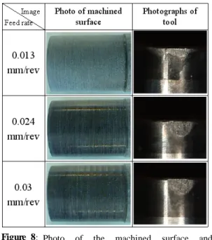
Figure 8: Photo of the machined surface and cutting tool according to the feed rate
according to each feed rate are shown in Figure 7. The trend of the temperature graph is similar to the case of 0.013mm/rev described earlier, but the slope and maximum temperature differ slightly. In order to visualize this, the degree of preheating according to the feed rate at a laser power of 800W is shown as a graph. As shown in the graph, a faster feed rate decreases the maximum temperature only slightly.
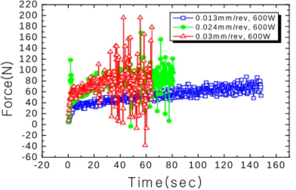
However, as shown by the surface photograph, changes in the surface according to the feed rate are large despite the small changes in the maximum temperature. The surface temperature was increased to a greater extent. Figure 8 shows a photo of a machined surface and cutting tool according to the feed rate. It was machined while varying the feed rate at 0.013mm/rev, 0.024mm/rev and 0.03mm/rev under fixed conditions of a rotational speed of 620rpm, a laser power of 600W and a cutting depth of 0.3mm.
Oxidation of the workpiece machined
surface appears to decrease slightly as the
feed rate is increased. Such phenomenon
appeared in all conditions. Increasing the
feed rate reduced the degree of change
insufficiently. Therefore, a better surface
status is expected to result by considering
the cutting force and cutting surface
status after taking the processing
variables into consideration. In addition,
the life of the tool is increased by
reducing the feed rate. Figure 9 shows a
measurement graph of the main cutting
force for each feed rate at a laser power of
600W. A faster feed rate increases the
-2 0 0 2 0 4 0 6 0 8 0 1 0 0 1 2 0 1 4 0 1 6 0 -6 0
-4 0 -2 0 0 2 0 4 0 6 0 8 0 1 0 0 1 2 0 1 4 0 1 6 0 1 8 0 2 0 0 2 2 0
Force( N)
T im e (s e c )
0 .0 1 3 m m /re v , 6 0 0 W 0 .0 2 4 m m /re v , 6 0 0 W 0 .0 3 m m /re v , 6 0 0 W