• 검색 결과가 없습니다.

Flicker Prevention and Noise Reduction Using Edge-Spike Modulation in Visible Light Communication

N/A
N/A
Protected

Academic year: 2021

Share "Flicker Prevention and Noise Reduction Using Edge-Spike Modulation in Visible Light Communication"

Copied!
7
0
0

로드 중.... (전체 텍스트 보기)

전체 글

(1)

http://dx.doi.org/10.5369/JSST.2018.27.3.143 pISSN 1225-5475/eISSN 2093-7563

Flicker Prevention and Noise Reduction Using Edge-Spike Modulation in Visible Light Communication

Seong-Ho Lee

+

Abstract

In this paper, we introduce an edge-spike modulation method for visible light communication (VLC). This method is effective in pre- venting LED flicker and 120 Hz noise interference in base-band VLC. In the VLC transmitter, edge-spikes are generated by passing the digital data through a simple RC-high pass filter (HPF). The LED modulation of the edge-spikes does not change the average power of the LED light; thus it prevents LED flicker. In the VLC receiver, the 120 Hz noise from other lighting lamps is easily eliminated by RC-HPF, while the edge-spike signal is detected normally. In our experiment, the message of an air-quality sensor was successfully transmitted using edge-spike modulation. This structure is useful in constructing, e.g., wireless gas monitoring sensor systems to warn and prevent harmful gas leakage accidents in buildings using LED light.

Keywords: Flicker, Noise reduction, Edge-spike modulation, High-pass filter, Visible light communication (VLC).

1. INTRODUCTION

Recent advances in semiconductor technology have led to the development of various types of high-power visible light emitting diodes (LEDs), with widespread and increasing applications such as street lighting, indoor lighting, and automobile lighting. The LEDs are advantageous because they have higher power efficiency, withstand mechanical impact better, and have a smaller radiating surface compared to conventional incandescent lamps and fluorescent lamps. In addition, the illumination of LEDs is easily controlled by adjusting the injection current. The modulation speed is also fast.

Due to the high-speed modulation characteristics of the LEDs, they have been widely used as light sources for visible light communication (VLC) in which illumination and communication are performed simultaneously [1-5]. VLC is a wireless short- distance communication method in which free space is used as the transmission medium between a light source and a photo-

detecting device. Visible light does not interfere with conventional radio frequencies and the signal exists only within the signal beam. Thus, VLC can be a good transmission method in places where it is required to prevent eavesdropping from outside the room or in places where electromagnetic interference should be prevented [2].

While VLC is advantageous because the same light source is used for both illumination and communication, much care should be taken in the system design so that the illumination and the communication do not affect each other. The base-band VLC system is simple and easy to implement. However, the LED light may change during communication due to irregular data transmission, which results in flicker. The flicker is an unstable illumination state in which the average power of the LED light changes, which might make people’s eyes uncomfortable [4].

To prevent the LED flicker in base-band VLC systems, special coding schemes such as the Manchester code or the pulse position modulation have been adopted generally in the transmitter.

However, the Manchester code or pulse position modulation requires additionally accurate clock sources for synchronizing the transmitter and the receiver.

Amplitude shift keying (ASK) and frequency shift keying (FSK) modulation, which use subcarriers of much higher frequency than the baseband signal, are good transmission methods to prevent the flickering of the LED light. In this case, additional oscillator circuits are required in the transmitter to provide carrier frequencies, and additional envelope detection Department of Electronics and IT Media Engineering, Seoul National

University of Science and Technology, 232 Gongneung-ro, Nowon-gu, Seoul 01811, Korea

+

Corresponding author: [email protected] (Received: Apr. 23, 2018, Accepted: May. 25, 2018)

This is an Open Access article distributed under the terms of the Creative Commons Attribution Non-Commercial License(http://creativecommons.org/

licenses/bync/3.0) which permits unrestricted non-commercial use, distribution,

and reproduction in any medium, provided the original work is properly cited.

(2)

circuits for the carrier frequency should be provided in the receiver. Thus, the system configuration becomes more complex than in the base-band VLC systems [5].

From another point of view, base-band VLC systems are sensitive to the 120 Hz noise interference from other lighting sources, such as incandescent or fluorescent lamps. Even some commercial LED lamps driven by adapters connected to a 60 Hz power line emit the 120 Hz noise depending on adapter type.

Because the VLC signal and the noise both are visible light, if the VLC receiver is exposed to the noise light from other lighting lamps, the noise causes interference. In the case that the noise is very weak compared to the signal amplitude, the noise can be easily eliminated using a simple electrical filter or threshold circuit. However, if the noise amplitude is not negligible, the base- band VLC system is not adequate and ASK and FSK modulation become effective methods to eliminate the noise interference.

In this paper, we introduce a new modulation method for base- band VLC systems, in which the LED light is modulated by the edge-spikes of the original data. By passing the data through a simple RC-high pass filter (HPF), edge-spikes are generated in the transmitter. The positive spikes appear at the leading edges, and the negative edge-spikes at the trailing edges of the original data.

The positive and the negative edge- spikes have the same amplitudes and the same shapes, however, they are inverted horizontally with respect to each other. Thus, when the LED is modulated by the edge-spikes, the average power of the LED light does not change and the LED light is kept flicker-free during data transmission.

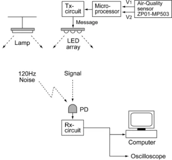
In the receiver, the 120 Hz noise contained in the photodiode voltage is cut off by an RC-HPF and only the edge-spike signal is detected. A microprocessor recovers the original data by generating a high voltage at the time of the positive edge-spike and a low voltage at the negative edge-spike. This method is very simple and easy to implement because only RC-HPFs are required. In our experiment, we used the edge-spike modulation for transmitting air-quality sensor data. This configuration is useful in constructing a wireless gas monitoring sensor system to prevent harmful gas leakage accidents in buildings using LED light.

2. EDGE-SPIKE TRANSMISSION

2.1 Edge-spike modulation

To prevent LED light flicker in the VLC transmitter and noise

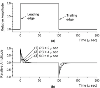
light interference in the VLC receiver, the LED is modulated by the edge-spikes of the original data. Figure 1 illustrates schematically the edge-spike modulation.

Figure 1(a) shows an example of the non-return-to-zero (NRZ) data to transmit, which denotes a character “V” in the universal asynchronous receiver-transmitter (UART) format. The American standard code for information interchange (ASCII) code of the eight-bit character “V” is “01010110”. In UART transmission, the least significant bit (LSB) is sent first, thus the bit sequence is reversed and becomes “01101010”. One start bit “0” and one stop bit “1” is added to the ASCII code, and the total bit sequence becomes the ten-bit signal “0011010101”. In a UART transmission, the high voltage (H) is assigned to bit “0” and the low voltage (L) to bit “1”. Thus, the character “V” has an NRZ waveform of “HHLLHLHLHL” as shown in Fig. 1(a).

In the VLC transmitter, an RC-high pass filter (RC-HPF) is used to generate the edge-spike signal. When the NRZ signal passes through an RC-HPF, the positive and the negative spikes appear at the leading edges and at the trailing edges, respectively, of the original NRZ signal as shown in Fig. 1(b). The positive and the negative edge-spikes have the same amplitude and the same shapes, but they are horizontally inverted with respect to each other. These edge-spikes are used to modulate the LED light for data transmission. In the VLC transmitter, when the LEDs are modulated by the edge-spikes, the average power of the LED light is kept constant because the positive and the negative edge-spikes have the same amplitude. Therefore, the LED light does not flicker during data transmission.

The edge-spike generation using an RC-HPF can be explained by a simple calculation. When a square wave passes through an RC-HPF, the positive and the negative spikes appear at the leading and the trailing edges, respectively. If a square wave input pulse has a leading edge at t=0 and a trailing edge at t=t

0

, the positive and the negative edge-spikes appear at the RC-HPF output, which Fig. 1. The original data and the edge-spike waveforms. The original

data and (b) the edge-spike waveforms.

(3)

can be written as follows [6]

(1)

where V

0

is the amplitude and RC the time constant. Figure 2 shows the edge-spike waveforms calculated from equation (1) when a square wave pulse is applied to an RC -HPF.

Figure 2(a) shows the square wave input and Fig. 2(b) the edge- spikes of the HPF output. In Fig. 2 (b), curves (1), (2), and (3) correspond to the RC-time constants 2, 4, and 6 μs, respectively.

The edge-spikes become sharper as the RC-time constant reduces.

The relation between the RC time constant and the 3-dB-cutoff frequency of the RC -HPF is

(2) The time constants of RC=2, 4, and 6 μs correspond to a RC- HPF cutoff frequency of f

c

=80, 40, and 27 kHz, respectively. In the experiment, we used R=400 Ω, C=10 nF for RC-HPF, whose RC-time constant and cut-off frequency were about 4 μs and 40 kHz, respectively.

In the VLC receiver, we used the same RC-HPF as that in the transmitter to eliminate the 120 Hz noise from other lighting sources.

The cutoff frequency of the RC-HPF is much higher than the 120 Hz noise frequency; thus it cuts off the noise while receiving the edge- spike signal. Therefore, the edge-spike modulation is used for two purposes: to prevent the flicker of LED light in the VLC transmitter and to eliminate the 120 Hz noise in the VLC receiver.

2.2 VLC transmitter

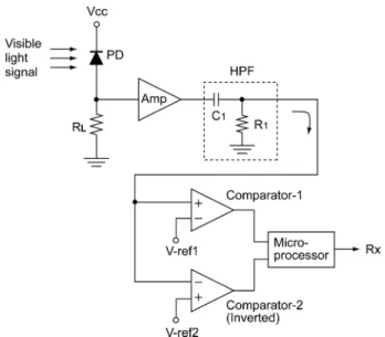
In the VLC transmitter, the LED current is modulated by the edge-spikes of the transmitted data. The schematic diagram of the VLC transmitter is shown in Fig. 3.

The input data is applied to an RC-HPF which is composed of a capacitor C

1

and a resistor R

1

. The RC-HPF generates the positive edge-spikes at the leading edges of the data and the negative edge-spikes at the trailing edges. The edge-spikes are applied to the gate of an FET, which is biased to operate in the linear region. The drain current passes through an LED array, and the LED light is proportional to the edge-spike signal. The LED light radiates into free space.

In our experiment, we used R

1

=400 Ω, C

1

=10 nF for RC-HPF, with a cut-off frequency of about 40 kHz. An OPA228 op-amp was used for the buffer, and an IRF540 FET for the LED current driver. The LED array was made of six 1W white LEDs in the form of a 2×3 planar array. To see the waveforms in the transmitter, the character “V” was generated by a microprocessor and applied to the input port of the VLC transmitter. Figure 4 shows the waveforms observed in the VLC transmitter with an oscilloscope.

Figure 4(a) shows the voltage waveform of the character “V” at the UART port of a microprocessor. It is an NRZ waveform at a

⎪⎩

⎪ ⎨

>

>

= +

− / 0 ) 0 (

0 /

; -

0 ) ;

( V e

0

t t

t e

t V

v

t t RC

RC t

f

C

2 π RC

= 1

Fig. 2. Calculated waveforms of a RC-high pass filter.

(a) The square wave input and (b) the edge-spikes at the out- put.

Fig. 3. Schematic diagram of the VLC transmitter.

Fig. 4. Observed waveforms in the VLC transmitter.

(a) The waveform of the transmitted data and (b) The edge-

spikes at the HPF output.

(4)

data rate of 9.6 kbps. Figure 4(b) shows the voltage waveforms of the RC-HPF output. Positive edge-spikes appear at the leading edges and negative edge-spikes at the trailing edges of the input data. The LED current was modulated by these edge-spikes. The LED light was radiated into free space and a VLC receiver was installed at a distance of about two meters to receive the visible light signal from the LED array.

2.3 VLC receiver

The configuration of the VLC receiver is shown in Fig. 5.

A PIN photodiode detects the visible light signal sent by the VLC transmitter. The voltage across the load resistor R

L

is amplified and passes through an RC-HPF which is composed of a capacitor C

1

and a resistor R

1

. The 120 Hz noise arising from other lighting sources near the VLC transmitter is eliminated by RC-HPF whereas the edge-spike signal from the VLC transmitter is detected normally. The positive and the negative edge-spikes have the same amplitude and the same shapes, albeit inverted horizontally; thus the average voltage of the RC-HPF output corresponds to ground.

The positive edge-spikes indicate the times of the low-to-high transitions of the NRZ data at the VLC transmitter. The negative edge-spikes indicate the times of the high-to-low transitions. Thus, the positive and the negative edge-spikes should be detected separately to find the start and stop times of the NRZ signal. This work is done by the two comparators in the VLC receiver. The comparator-1 detects only the positive edge-spikes and cuts off the negative edge-spikes. The comparator-2 is an inverted comparator

and detects only the negative edge-spikes and cuts off the positive edge-spikes.

The microprocessor generates a high voltage at the time that the comparator-1 outputs a spike. In the same manner, the microprocessor changes its output voltage to the low state at the time that the comparator-2 outputs a spike. As a result, the output voltage of the microprocessor generates the same waveforms as the input data sent by the transmitter.

We used a silicon PIN photodiode BPW-34 as light detector, OPA228 op-amps for the amplifier and the two comparators, and the microprocessor was an Atmega8. We used R

1

=400 Ω and C

1

=10 nF for RC-HPF, with a cut-off frequency of about 40 kHz.

Figure 6 shows the waveforms in the VLC receiver observed with an oscilloscope.

Figure 6(a) shows the photodiode voltage amplified by an op-amp, in which the edge-spikes sent by the VLC transmitter are mixed with 120 Hz noise. The large slope in the signal was due to the 120 Hz noise from other lighting sources in the ceiling of the laboratory. The noise amplitude was about 4 Vpp when the edge-spike amplitude was 2.5 V. In this case, the noise amplitude was larger than the edge-spike signal. Thus, if the LEDs were directly modulated by the NRZ data instead of the edge-spikes in the transmitter, the signal would be seriously distorted and transmission errors would occur in the VLC receiver.

Figure 6(b) shows the HPF output voltage in which the large voltage variation due to the 120 Hz noise is eliminated and only the edge-spikes appear. Figure 6(c) shows the output voltage of the comparator-1 in the VLC receiver. In this waveform, only the positive edge-spikes appear and the negative edge-spikes are cut off. The reference voltage of the comparator-1 was set to 0.5 V. Figure 6(d) shows the output voltage of the comparator-2 in the VLC receiver. The

Fig. 5. Schematic diagram of the VLC receiver.

Fig. 6. Observed waveforms in the VLC receiver.

(a) Photodiode voltage, (b) HPF output signal, (c) compar-

ator-1 output, (d) compatator-2 output, and (e) data wave-

forms recovered by the VLC receiver.

(5)

comparator-2 is an inverted comparator as shown in Fig. 5.

Thus the positive edge-spikes are cut off and only the negative edge-spikes are detected with their polarity inverted by the comparator-2. As a result, the comparator-2 outputs positive spikes only at the time of the negative edge-spikes. The reference voltage of the comparator-2 was set to -0.5 V.

Figure 6(e) shows the waveforms recovered by the microprocessor. At the time of the positive edge-spikes the microprocessor generates high voltages, and at the time of the negative edge-spikes it changes to low voltages. Thus, the output voltage of the microprocessor becomes the same waveforms as the NRZ data sent by the VLC transmitter.

3. EXPERIMENT

As an application of the VLC system, the data of an air-quality sensor was transmitted using the LED light. The air-quality sensor was ZP01-MP503, which detects volatile gases such as carbon monoxide, ammonia, alcohol, smoke of cigarettes, etc. The VLC system with the air-quality sensor can be used in an office or a corridor for real-time monitoring of air quality changes and for

warnings in emergency situations. The experimental setup is shown in Fig. 7.

The air quality sensor outputs two voltages (V

1

, V

2

) depending on the air pollution state [7], as shown in Table 1.

A microprocessor reads the two voltages V

1

and V

2

from the air- quality sensor and sends the corresponding pollution grade message to the VLC transmitter. The VLC transmitter modulates the LED light using the edge-spikes of the message data. The edge-spikes do not change the average optical power of the LED light; thus the LED array does not flicker. Figure 8 shows the signal waveforms in the VLC transmitter observed with an oscilloscope.

Figure 8(a) shows the NRZ data waveform from the microprocessor, which corresponds to the characters

“\tCLEAN\r\n”. This message indicates that the two voltages of the air-quality sensor are V

1

=0 and V

2

=0 as shown in Table 1.

Figure 8(b) shows the edge-spikes at the RC-HPF output in the VLC transmitter. The LED array in the VLC transmitter was modulated by these edge-spike waveforms.

We installed a VLC receiver on a table about 2 meters from the VLC transmitter. Near the VLC transmitter, other lighting lamps for indoor illumination were installed. These lamps were driven

Table 1. Air-quality sensor output voltages.

V

1

V

2

Pollution grade

0 V 0 V Clean

0 V +5 V Light pollution

+5 V 0 V Moderate pollution

+5 V +5 V Severe pollution

Fig. 7. Experimental setup.

Fig. 8. Observed waveforms in the VLC transmitter.

(a) Data waveforms from the microprocessor and (b) edge- spike waveforms of the data.

Fig. 9. Observed waveforms in the VLC receiver.

(a) Photodiode voltage, (b) HPF output voltage, (c) com-

parator-1 output, (d) comparator-2 output, and (e) the recov-

ered data in the microprocessor.

(6)

by a 60 Hz power line and emitted 120 Hz noise light. The noise light and the VLC signal are all visible lights; thus the noise from the other lamps interferes with the signal in the base-band VLC receiver. Figure 9 shows the waveforms in the VLC receiver observed with an oscilloscope.

Figure 9(a) shows the photodiode voltage, in which the edge- spike signal from the transmitter and the 120 Hz noise were mixed. If the data were modulated directly by the base-band NRZ data instead of the edge-spikes in the transmitter, the data would be seriously affected by the noise interference because the noise amplitude is larger than the signal.

Figure 9(b) shows the RC-HPF output voltage in which only the edge-spikes appear and the 120 Hz noise is almost eliminated.

Figure 9(c) shows the output voltage of the comparator-1, in which only the positive edge-spikes are present. These positive spikes were used to initiate the microprocessor to generate a high output voltage in the VLC receiver. Figure 9(d) shows the output voltage of the inverting comparator-2, in which positive spikes appear only at the time of the negative edge-spikes. These spikes were used for changing the microprocessor output voltage to a low state. Figure 9(e) shows the output voltage of the microprocessor in the VLC receiver. This is the recovered data and is the same as the NRZ data sent by the VLC transmitter in Fig. 8(a).

The recovered data in the VLC receiver were transmitted to a computer and on a monitor. Figure 10 shows the characters displayed on the monitor.

The characters “CLEAN” on the monitor were the data sent by the VLC transmitter denoting that the air condition was clean.

Among the characters “\tCLEAN\r\n” sent by the transmitter, “\t”

(horizontal tab), “\r” (carriage return), and “\n” (line feed) do not

appear on the screen because they are special characters to control the position of characters on the monitor. Through this experiment, we saw that the LED light was kept flicker-free and the 120 Hz noise interference was eliminated using the edge-spike modulation method. Figure 11 shows the circuit boards used in the experiments.

Figure 11(a) shows the air-quality sensor ZP01-MP503 and Fig.

11(b) the LED array with its current driving circuit. The LED array was made in a 2×3 planar array form, and was used for the light source in the VLC transmitter. Figure 11(c) shows the PIN photodiode BPW-34 with a lens attached and Fig. 11(d) the microprocessor Atmega8 circuit. We used the same kind of microprocessor circuits in the VLC transmitter for message generation and in the VLC receiver for data recovery.

4. CONCLUSIONS AND DISCUSSION

In this paper, we have developed an edge-spike modulation method for base-band VLC system. The edge-spike modulation was used for two purposes: to prevent the flicker of LED light in the VLC transmitter and to eliminate the 120 Hz noise in the VLC receiver.

In the VLC transmitter, a simple RC-HPF was used to generate edge-spikes from the NRZ data. When the LED light was modulated by the edge-spikes, the average power of the LED light did not change. Thus it was flicker-free. In the VLC receiver, the 120 Hz noise light interference from other lighting sources was easily eliminated by an RC-HPF while the edge-spike signal was detected.

Fig. 10. The characters displayed on a monitor.

Fig. 11. The circuit boards used in experiments.

(7)

In the transmission experiment, we used the VLC system with edge-spike modulation to transmit the data of an air–

quality sensor. The VLC system did not affect the illumination condition because the LED light was kept flicker-free. At the same time, the other lighting did not interfere with the VLC system because it prevents the 120 Hz noise. This structure is very simple to implement and useful in constructing wireless gas monitoring sensor systems using the LED light to warn and prevent harmful gas leakage accidents in buildings.

ACKNOWLEDGMENT

This study was supported by the Research Program funded by the SeoulTech (Seoul National University of Science and Technology).

REFERENCES

[1] T. Komine and M. Nakagawa, “Fundamental analysis for visible-light communication system using LED lights”, IEEE Trans. Consum. Electron., Vol. 50(1), pp. 100-107, 2004.

[2] Y. K. Cheong, X. W. Ng, and W. Y. Chung, “Hazardless biomedical sensing data transmission using VLC”, IEEE Sens. J., Vol. 13(9), pp. 3347-3348, 2013.

[3] S. H. Lee, “A passive transponder for visible light iden- tification using a solar cell”, IEEE Sens. J., Vol. 15(10), pp.

5398-5403, 2015.

[4] S. Rajagopal, R. D. Roberts, and S. K. Lim, “IEEE 802.15.7 visible light communication: modulation schemes and dim- ming support”, IEEE Comm. Mag., Vol. 50(3), pp. 72-82, 2012.

[5] C. Yao, Z. Guo, G. Long, and H. Zhang, “Performance Comparison among ASK, FSK and DPSK in visible light communication”, Opt. Photon. J., Vol. 6(8B), pp. 150-154, 2016.

[6] C. K. Alexander and M. N.O. Sadiku, Fundamentals of electric circuits, 4

th

ed., McGraw-Hill, pp. 253-257, 2009.

[7] Zhengzhou Winsen Electronics Technology, Air quality

detection module user’s manual, p.5, 2014.

수치

Fig. 2. Calculated waveforms of a RC-high pass filter.
Figure 6 shows the waveforms in the VLC receiver observed with an oscilloscope.
Table 1. Air-quality sensor output voltages.
Fig. 10. The characters displayed on a monitor.

참조

관련 문서

The index is calculated with the latest 5-year auction data of 400 selected Classic, Modern, and Contemporary Chinese painting artists from major auction houses..

1 John Owen, Justification by Faith Alone, in The Works of John Owen, ed. John Bolt, trans. Scott Clark, "Do This and Live: Christ's Active Obedience as the

- Transition to H-mode: state with reduced turbulence at the plasma edge - Formation of an edge transport barrier: steep pressure gradient at the edge...

(1) The sheet hot-rolled at lower hot-rolling temperature and higher reduction rate revels many cracks at the edge of the hot-rolled sheet in Mg-Al-Zn

The academic journals used at the time were ‘The Mathematical Education’ of The Korean Society of Mathematical Education, ‘Journal of Educational Research

In this study, it is shows that the stream of CO 2 is more effective in the reduction of unreacted TEGDMA and the increase of surface microhardness than that of N 2

To examine the characteristics of its cutting edge, the material was trimmed to make a rectilinear cutting edge, and in addition to the cutting edge of the

– The rate at which the temperature at a point is changing with time The rate at which the temperature at a point is changing with time is proportional to the rate at