1. Introduction
Most of structures are now composed of steel and concrete and may cause structural collapse due to chemical reaction in materials, influence of external force, earthquake, and structural defect as time passes. For this reason, all the structures need to be carried out safety check-up periodically, and require maintenance with the security in stability, by evaluating state and stability in tunnel, by repairing and reinforcing, and by maintaining recovery of performance. What can be said to be most basic item in safety check-up may be said to be visual inspection. In particular, the visual inspection on crack in concrete is an important element in evaluating the state in the inside and outside of structure and in deciding on items and methods of performing the locally precision safety check-up in the next stage. However, as for the structure that is large section as tunnel and whose extension length is long, the existing
visual inspection of using a crack ruler and a crack mirror leads to allowing the survey time to take long and to being difficult for objective survey. Thus, the survey method came to require automation, accuracy, and promptness. In recent days, the external-survey technique and systems of using laser and vision sensor were developed and are being used gradually. Each system has merits and demerits. However, even among these things, a method of surveying the external state through image, which was obtained by using vision sensor, is more excellent than other systems in merits such as performance and quick survey time in comparison with the implemented cost, thereby being trend to be preferred. However, the methods of using this image processing technique have great influence in characteristics by each system and in the field environmental condition in terms of a part on reliability of data. Thus, the obtained data is difficult to be regarded as the reliable data, and is difficult to
Calibration of Detection System of Crack in Concrete Structure by Using Image Processing Technology
Su-Un Kim*, Sung-Woo Shin*, Jeong-Hak Park** and Man-Yong Choi**
Abstract The investigation of concrete structure typically relies on visual inspection which is one of the basic inspection techniques. Image processing techniques play a crucial role in the growing field of automatic surface inspection technique. However, kinds of inspection equipment, environmental condition and detection algorithm have much influence on the reliability of inspection result. This paper proposes a verification method and testing procedure for the reliability of inspection results and surveys characteristics of image acquisition systems and crack inspection algorithms.
Keywords: Non-Destructive Inspection, Calibration, Image Processing [Original paper]
Journal of the Korean Society for Nondestructive Testing Vol. 31, No. 6 (2011. 12)
[Received: September 15, 2011, Revised: November 22, 2011, Accepted: December 8, 2011] *Department of Architecture Engineering, Hanyang University, Haengdang-dong, Seongdong-gu, Seoul 133-791, Korea, **SM Center, Korea Research Institute of Standards and Science Doryong-dong 1, Yuseong-gu, Daejeon 305-340, Korea
Corresponding Author: [email protected]
be seen as a verified method unless passing through the right verification test on the variable of environmental condition and on characteristics in the width of crack in the stage of development. Accordingly, the verification device and method are needed that can measure reliability on measuring crack in these systems.
1.1 Research Objective and Contents
The purpose of this study was to propose the evaluation device and the evaluation software in the reliability verification that can evaluate reliability in detecting and measuring crack, by analyzing characteristics in the crack detection system of using vision sensor and image processing technique, by classifying the relevant factors, and by analyzing its effects.
And, for the more reliable crack measurement, it suggested the development in Calibration device and a method of using this.
2. Analysis of Influential Factors in the Crack Detection System of Using Digital Image Processing Technique
2.1 Principle of the Crack Detection System
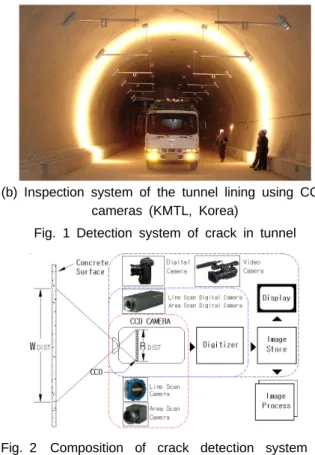
The present status for a system of detecting crack in tunnel by using vision sensor and digital image processing at home and abroad is as Fig. 1. In particular, it is being much used actually in Japan as the external-survey method for safety check-up in tunnel. Even in addition to this, the crack detection systems of using vision sensor are being developed continuously such as portable system of easily detecting crack by using vision sensor, system of detecting crack in tunnel by using single vision sensor, and device of detecting crack in remote-distance structure of using vision sensor.
These systems are the methods of obtaining value of information on width and length by
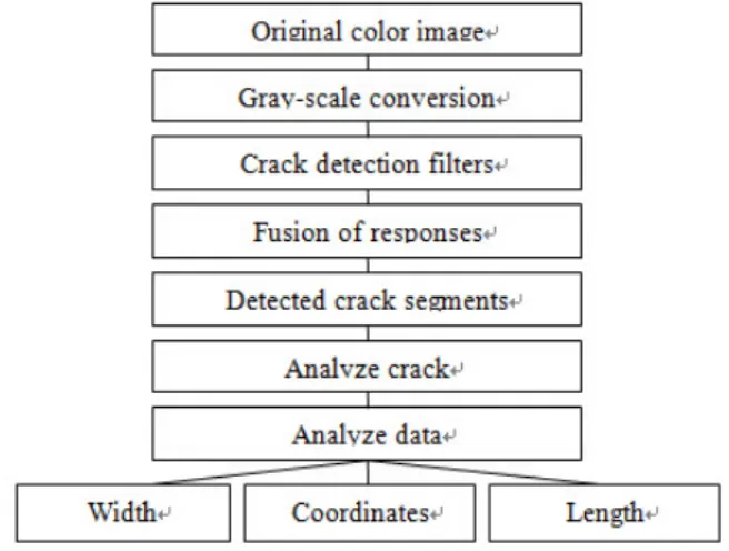
acquiring and analyzing image through using vision sensor and by detecting the crack part on the surface as for concrete structure. The use of this method leads to being capable of surveying more quickly and accurately than the existing visual inspection by a person. Especially, in case of structure whose extension length is long and whose section is big as the tunnel (subway, road tunnel, and waterway tunnel, etc.), the use of this method leads to being able to see great effect in the temporal and economical aspect and in the accuracy. Given examining the principle of this crack detection system, it is as Fig. 2.
(a) Inspection system of the tunnel lining using an infrared camera and CCD cameras (Teito Rapid Transport Authority, Japan).
(b) Inspection system of the tunnel lining using CCD cameras (KMTL, Korea)
Fig. 1 Detection system of crack in tunnel
Fig. 2 Composition of crack detection system in concrete structure
As for the surface of concrete structure, the analytical information (width, length, etc.) on crack and the crack processing image are obtained by changing the image signal, which was gained by using vision sensor, into the digital signal, storing it with image data, and then processing image. Factors, which influence here, include angular resolution in vision sensor, detection algorism, lighting condition, vibration, velocity, lens distortion, and angle with camera and shooting side. In particular, the angular resolution in vision sensor and the detection algorism come to have the greatest influence upon error in the crack-measurement value. And, this study described contents on this.
2.2 Angular Resolution in the Crack Detection System
In order to calculate width, length and others in crack, the real length, which is indicated by 1 pixel, needs to be known, thereby being able to be obtained given knowing the concrete surface area, which is shot by camera, and the pixel number in vision sensor.
DIST DIST
l R
P W (1)
Here,
Pl : real length indicated by one pixel (mm/pixel)
WDIST : length in one side of the views (e.g. X-axis length)
R
DIST :pixel number in one side of CCD (e.g. X-axis pixel number)The minimum width in crack measurement is determined by considering the pixel size as the calculating formula (1) given shooting concrete structure. In other words, given trying to measure up 0.1 mm in the width of crack in
case of detecting width of crack by calculating pixel number, which is a general method of detecting crack, the actual length, of which one pixel is in charge at least, should be less than 0.1 mm. Accordingly, it shoots by establishing the area to be shot as angle of view in camera by considering the minimum width in crack measurement. However, this calculation of width, which uses pixel number, is reduced accuracy more in the less pixel number within the width of crack. This is because pixel is a tetragonal shape, thereby leading to difference in real length, of which one pixel is in charge, when crack is not the vertical-horizontal direction. When utilizing a system of using this system now, there needs to be enough consideration on this problem. This study aims to propose verification system that can test reliability and accuracy in the existing crack detection systems, by considering these characteristics.
2.3 Examination of Image Process in Crack Detection and Measurement
Image process in crack detection and measurement is as Fig. 3. Image signal, which entered through vision sensor, is changed into digital signal through digitizer, and is stored in the storage device. The stored data comes to pass through the image processing stage as Fig.
3 in order to detect and measure crack. Given indicating this with a picture, it is as Fig. 4.
In order to extract only crack following 8bit black-and-white image processing as for the original image, which was obtained through camera, several filtering works are performed.
Here, as the process of crack detection filters is the one in order to separate the crack sphere and the non-crack sphere (background), it is generally form with histogram equalization and binarization.
As histogram equalization is what improves the contrast in image by correcting effect caused by light and noise, topology technique is used[5].
As for pixels that have diverse brightness values following histogram equalization, the crack part and the non-crack part are separated by changing brightness value in pixel into 0(black) and 1(white) based on optional threshold value. Width, length, and coordinates
are calculated by using pixel within the crack sphere after passing through this process. A calculating method was proposed diverse methods by many researchers. Several methods are being used every crack detection system[1-4].
What is an important problem in this image processing process is shown in the process of crack detection filters, which extracts only the crack part. Still, as shown in Fig. 5, the histogram value of boundary-part pixel in the crack sphere and the non-crack sphere is shown ambiguous difference from the histogram value in the central part of the crack sphere.
Accordingly, depending on establishing the uncertain threshold value, a big error may occur in the measurement of width in crack. In order to reduce this error and to develop the more enhanced algorism, the experimental device is desperately needed that is available for quantitative experiment.
2.4 Verification of Measuring Width in Crack
The most important part in a crack measurement method of using image processing is reliability in the measurement result. In particular, the measurement value on width is the most important item that has effect on durability and safety in concrete, and is higherin precision (0.1 mm in unit), which is required, than length and location. Accordingly, given examining a research on this field so far on a method of verifying reliability on the measurement value in width of crack, generally as Fig. 6, the actual width of crack in concrete was measured and marked by using microscope or crack ruler, and was compared with the result value in image processing[6,7].
Verification by measuring width in actual crack with crack microscope in this way is one method. However, there is necessity for device available for quantitative verification in order to verify width in the more correct crack.
Fig. 3 Digital image processing course
Fig. 4 Image processing and crack analysis
Fig. 5 Crack image
Fig. 6 Verification of crack-measurement result
3. Development in a System of Verifying Reliability in the Crack Detection Device
3.1 Development in Device of Verifying Reliability in the Crack Measurement
The crack detection system in the concrete structure of using vision sensor requires complex technology such as optics, electronics, mechanism, and computer science. This is because a method of using vision sensor can cause error in the measurement value of data according to environmental influence of the survey field in light of its feature. Aiming at measurement with reliability, the experiment and verification are needed on the environmental elements such as light, vibration, velocity, distance, lens distortion and on algorism of calculating width of crack according to features in CCD pixel. For the more correct verification on the conventional method of verifying width in crack, the verification system in Fig. 6 was developed that can verify a change and reliability in width of crack according to environmental elements such as angle &
distortion in camera shooting, and effect of light.
As for structure in this device, several kinds of vision sensors can be fixed. The width in crack can be controlled owing to being mounted the camera posture controller available for controlling distance and angle from specimen, and the specimen in diverse materials. It is
composed of a crack-width controller available for revolution, a base device available for measuring the distortion level in shooting image, the views & length, and a lighting device available for controlling illumination in the views and controlling angle in the views and light source. A camera in the crack detection system, which will verify, is mounted on the posture controller. It shoots while proceeding with controlling the corresponding devices by item, which desire to be verified. After then, the measurement result in the width of crack is elicited and is verified in comparison with the SET value in the width of the verification device, by applying algorism, which is used by its system. The functions in the reliability verification system and the verification items are as Table 1.
3.2 Development in Software of the Crack- Measurement Reliability Test
The image processing software was developed that is available for experiment by Table 1 Principle and verification in the reliability
verification device
Functions Calibration items
Posture controller in Vision sensor
Angle control with specimen 20˚~90˚
Change in the crack width on
angle with specimen Distance control
with specimen 20cm~180cm
Distortion phenomenon on
distance with specimen
Crack-width controller
Crack-width control in
specimen 0.01mm~200mm (0.01mm in unit)
Crack-width measurement
reliability
Angle control in specimen 0˚~180˚
Change in the measurement value of the width
on angle in crack
Base panel
Grid surface treatment
Distortion Value Measurement 1mm in unit scale Shooting area
image-processing stage in the acquired crack image, and for general analysis on its influence.
Fig. 7 is showing the main screen in software.
This software was developed with Boland C++, and was developed in order to possibly apply to image and to analyze it by mounting several techniques on the image processing. The detailed functions are as Table 2.
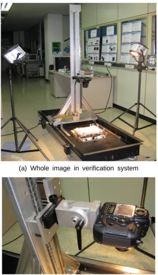
(a) Whole image in verification system
(b) Device of controlling posture of vision sensor
(c) Device of controlling width in crack Fig. 7 System of verifying reliability
Table 2 Functions of reliability verification program Functions Detailed functions Image Type BMP,JPEG,TIFF,PCX,WMF,EMF,P
NG,TGA,EPS
Histogram
Enhancement in contrast of color, Histogram equalization, Gaussian
filter Edge extraction
and noise filter Sobel, Prewitt, Laplace, Median Morphology Dilation, Erosion, Open, Close Binarization and
morphology filter
Binarization Threshold Value setting, Global binarization, Local
binarization, Dilation, Erosion Crack
measurement Crack automatic measurement
4. Development in the Crack-Width Verification Device of Using the Reliability Verification System
4.1 Crack-Width Measurement Experiment
The crack-width measurement experiment was performed in order to research into the setting and the verification method in Threshold Value proper for crack, which is the most important item shown in image, by using the developed reliability verification system.
The vision sensor, which was used for obtaining the crack image in this experiment, is Nikon D2x, which was mounted CMOS censor, in 23.7×15.7 mm of size. And, the valid pixel is 12.4 Megapixel. As the film valid pixel supports three modes in L, M, S, this experiment was used S mode: 2144×1424 pixel. Lens was used NIKKOR 18-55 mm. Setting was made as Fig. 7 (a, b). Camera forms perpendicularity in specimen. As formula (1), the view was set to 214.4×142.4 mm. Actual length, which is indicated by one pixel, was set to making it 0.1 mm. As for lighting, 2 pieces of 650W tungsten halogen lamp were arranged in order to be 60° with specimen. Brightness on the specimen was uniformed, thereby having
minimized effect on light.
Experiment acquired image while changing each of crack width up to 0°~90° by 10°, with increasing crack width up to 0.1 mm~0.9 mm by 0.1mm. Binarization was performed right after changing the acquired image by each case into 8 bit gray-scale. Histogram equalization was omitted. Reasons for omitting histogram equalization are because the effect on light was minimized in the experimental condition, because the color of surface in specimen is equal, and because of excluding the effect of histogram equalization on crack width.
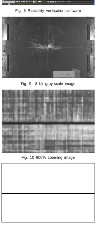
Given briefly explaining one example (0.1 mm 0°) out of experiment by case along with photo, those are as follows.
First of all, given changing original image into gray-scale, it is as Fig. 8. In order to help understanding of description, a picture, which was indicated by expanding the central part in Fig. 8, is as Fig. 9. Here, the corresponding pixel to crack needs to be indicated theoretically to be 1 pixel line. However, as shown in the figure, pixels are seen that have similar value to the crack sphere in the adjacent pixel line to 1 pixel line in the crack sphere. This phenomenon is the one that is shown in most of crack images, and is thought to be attributable to the influence of location in crack width, interference in light, and accuracy in the shooting area, in the arrangement of photo diode in CCD. Here, depending on how threshold value for binarization is established, the crack value may be 0.1 mm, 0.2 mm or 0.3 mm. However, the crack-width value, which was set in the experimental condition, is 0.1 mm, thereby having been able to be known that the pixel line, which is shown most darkly in the central part, is crack, and that threshold value of binarization in this pixel line is 37. The image, which binarized it with the value of 37, is as Fig. 10.
Fig. 8 Reliability verification software
Fig. 9 8 bit gray-scale image
Fig. 10 800% zooming image
Fig. 11 Threshold value: 37
Fig. 12 Calibration panel
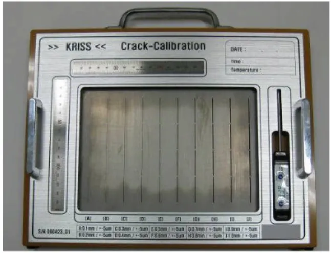
Through this experiment, the threshold value in binarization could be obtained aiming at the characteristics in crack, which are shown in image, and at the correctly crack extraction by each case. As a result of this, for the more correct result in measuring crack in concrete, Fig. 11 for calibration device was devised. The crack panel, which is the main component equipment in this device, was processed a groove with unit of width in 0.1 mm up to 0.1 mm~1.0 mm by using laser, with SUS material in the less thermal deformation.
Precision is ±5㎛. Other than it, the component device consists of a thermometer, which measures the ambient temperature available for grasping thermal deformation, a measurement device available for grasping angle, and 2 rules, which marked length.
The proposed usage may be employed for extracting actual crack in concrete by acquiring image through shooting this device along with concrete surface and through obtaining threshold value of binarization in calibration panel image as the above-describe method.
5. Conclusions
This study analyzed on factors, which have influence upon error in the crack measurement value, which is being proposed in operating the
crack detection system in a structure of using the current image processing technique, and suggested the basic standard system available for analyzing on factors that have effect on the error in the crack measurement value. Also, in order to solve this, a system was suggested for verifying reliability in crack detection systems.
This verification system can evaluate items such as a change in crack width on the shooting angle, phenomenon of distortion on the shooting distance, the minimum width in crack available for measurement, a change in width measure- ment value on angle in crack, distortion calibration ability, the maximum and minimum angle of view on distance, appropriateness for the lighting design, and the optimal illumination, and will be able to offer the more reliable data in the concrete non-destructive inspection by evaluating reliability in the crack detection system by using this verification system.
Through this study, a new method was presented on what obtains Threshold Value in binarization, which is an important element in deciding on the crack measurement value. The experiment by angle in each crack width led to having discovered the difference in threshold value to be applied depending on angle. The aim is to analyze on characteristics in crack according to angle by supplementing this more in a future research.
Acknowledgement
This work was supported by the New &
Renewable Energy of the Korea Institute of Energy Technology Evaluation and Planning (KETEP) grant funded by the Ministry of Knowledge Economy, Republic of Korea New&Renewable Energy.
References
[1] T. Doihara, K. Hirono and K. Oda, "Crack
measuring system based of hierachical image processing technique," International Archives of Photogrammetry and Remote Sensing, Vol. 29, No. 5, pp. 155-159 (1993)
[2] C. Qi and J. Weiss, "Characterization of plastic shrinkage cracking in fiber reinforced concrete using image analysis and a modified weibull function,"
Materials and Structures, Vol. 36, No. 26, pp. 386-395
[3] L. Li, P. Chan and R. L. Lytton,
"Detection of thin cracks on noisy pavement images," ASCE Transportation Research Record 1311, pp. 131-135 (1991) [4] K. Pratt. William, "Digital Image Processing," 3rd Ed. John Wiley & Sons, Inc (2002)
[5] R. C. Gonzalez and P. Wintz, "Digital Image Processing," 2nd Ed., Addison Wesley Longman (1987)
[6] B.-Y. Lee, "Development of detecting system for concrete surface cracks using image processing and artificial neural network," Master's Thesis, Korea Advanced Institute of Science and Technology (2004)
[7] G. D. Schutter, "Advanced monitoring of cracked structures using video microscope and automated image analysis," NDT & E International : Independent Nondestructive Testing and Evaluation, Vol. 35, No. 4, pp. 209-212 (2002)
[8] T. Asakura and Y. Kojima, "Tunnel maintenance in Japan," Tunneling and Underground Space Technology 18, pp.
161-169 (2003)
[9] F. L. J. Sangster, "Bucket brigade electronics-new possibilities for delay axis conversion and scanning," IEEE J. of Solid-State Circuits, SC-4, pp. 131-136 June (1969)
[10] W. A. Adcock : "Electronic still Picture Photography System," US Patent 4057830, Nov. 8 (1977)
[11] R. Crane, "A Simplified Approach to Image Processing," Prentice-Hall (1997) [12] W. S. Boyle and G. E. Smith, "Charge
coupled semiconductor devices," Bell Syst.
Tech. J., 49, pp. 587-593 (1970)
[13] G. F. Amelio, M. F. Tompsett and G. E.
Smith, "Experimental verification of the charge coupled devices concept," Bell Syst.
Tech. J., Vol. 49, pp. 593-600 (1970)