통신해양기상위성 Ka 대역 통신탑재체 성능검증
정회원 이 용 민P
*
P, 이 성 팔P
**
P
Performances Evaluation of Ka Band Communications Transponder for COMS
Yong-min Lee*, Seong-pal Lee** Regular Members
요 약
통신해양기상위상은 국내 정지궤도 복합위성 중의 하나이며, 2009년 아리안 로켓 V호에 의해 동경 128도 에 발사될 예정이다. 통신해양기상위성은 위성통신, 해양 및 기상관측 등의 세가지 임무 수행을 위해 설계, 제 작되었으며, 보다 구체적으로는 세 개의 서로 다른 탑재체에 의해 기상관측, 해양관측 그리고 Ka 대역의 위성 통신 서비스를 제공한다. 이 세 개의 탑재체 중에서 Ka 대역 통신 탑재체는 한국전자통신연구원에 의해 개발 되었으며 재해 방재를 위한 디지털 전송서비스와 고속 멀티미디어 서비스를 위한 디지털 통신서비스를 제공하 게 된다. 본 논문은 통신해양기상위성 Ka 대역 통신 중계기 비행모델의 전기적, 기계적 설계 및 지상검증을 위 한 시험 측정결과 등에 관한 것이다..
Key Words : hybrid geostationary satellite; satellite communications; COMS; Ka band; transponder
ABSTRACT
COMS is the one of Korean hybrid geostationary satellite and is scheduled to be launched in 2009 by Arian V into 128° E longitude. COMS is designed and manufactured for three main objectives which are Communications, Oceanographic, and Meteorological missions. It provides the weather monitoring, ocean monitoring, and Ka band satellite communication services by means of three different payloads. The Ka band communications payload was developed by Electronics and Telecommunications Research Institute (ETRI), and provides not only the digital transmission for the communication services against natural disaster but also digital transmission for the high speed multimedia services. This paper describes the overview of the electrical and mechanical design and measured performances of the Ka band communications transponder flight model (FM) for COMS.
I. TIntroductionT
The satellite communications offer obvious advantages with respect to cable networks: the architecture is scalable; the diffusion throughout the land is wide; the bandwidth availability is high, in particular in the Ka band, and often less affected by congestion than terrestrial networks; satellite links are often private lines, unlike submarine and overland networks.
The Communication, Oceanographic, and
Meteorological Satellite (COMS) will be consisting of communication, ocean and meteorological payloads as a hybrid satellite. The major mission objectives of COMS are the weather monitoring, ocean monitoring, and satellite communication.
SATellite COMmunication (SATCOM) system is to be applied in the COMS which is to be launched in 2008.[1] SATCOM system is conducted for in-orbit verification of the developed Ka band communication payloads and experiment of wide-band multi-media communication services by ETRI. In order to achieve
** 한국전자통신연구원 광역무선기술연구부 위성탑재시스템연구팀(HTU[email protected]UTH)
** 한국전자통신연구원 광역무선기술연구부 위성탑재시스템연구팀 (HTU[email protected]UTH) 논문번호 : K3-2-8 , 접수일자 : 2008 년 12 월 8 일, 최종게재논문통보일자 : 2008 년 12 월 26 일
※ 본 연구는 지식경제부 및 방송통신위원회의 IT 신성장동력핵심기술개발사업의 일환으로 수행하였음. [2008-S-301-03, 통신 해양기상위성 위성통신시스템기술개발]
this objective ETRI has completed the design, manufacturing and verification by ground test to the Ka band communications transponder - an effort which included clarifying requirements, refining mission description and operation, determining the configuration of the payload, and anticipating the performances, assembly, integration & test, and so on.
Ⅱ. Electrical Design
2.1. Design Approach
The Ka band communications transponder mainly used for Korean domestic communication services requires high efficiency repeater which is applied the on-board switching techniques to be handled 3 multi-beams.
The transponder employs the double frequency translation and 100MHz channel bandwidth. The channel amplifiers with ALC and fixed gain control are fully compatible with the following types of transmission:
1) Digital Transmission for the communication services against natural disaster:
• Single carrier wideband digital burst, for data rates 56kbps ~ 10 Mbps using TDM-M-ary PSK.
• QPSK(and/or BPSK)-TDMA digital two-way subscriber service with Hub control station and remote terminals.
• Communication type services such as prediction, prevention, and recovery service for natural disaster.
2) Digital Transmission for the high speed multimedia services:
• Single carrier narrowband digital burst, for data rates 30Mbps ~ 155 Mbps using TDM- M-ary PSK.
• 8PSK (and/or QPSK, BPSK)-TDMA digital two-way subscriber service with Hub control station and remote terminals.
• Multimedia type services such as Internet via satellite, remote medicine, distance learning etc.
3) Analog Transmission
2.2. Transponder Configuration
The high throughput requirements for the Ka band communications transponder are determined taking into account multi beam input/output and on-
board switching configuration. The overall major requirements for frequency allocation and gain performances are summarized in Table 1.
Table 1. Main Design Targets of Transponder
Parameters Features Service area Korea peninsula
Relevant frequency
band Ka band
Orbit and position Geostationary at 128.2°E Service Life More than 7 years
G/T 13.0 dB/°K
EIRP 58.0 dBW
The Ka band communications transponder for COMS is required to provide 3 input and 3 output for on-board switching and 3 individual spot beams simultaneously. The simple 3 channels transponder is applicable to this configuration; however, it suffers a more complexity due to the redundancy scheme of each channel.[2]
The Ka band transponder provides four active 30/20 GHz channels, two antennas, and a beacon assembly as shown in Figure 1.
Fig. 1 Functional Block diagram of Ka band Communications Transponder
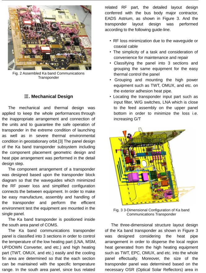
Figure 2 shows the assembled Ka band communications transponder just before mounting on the bus structure.
Fig. 2 Assembled Ka band Communications Transponder
Ⅲ. Mechanical Design
The mechanical and thermal design was applied to keep the whole performances through the inappropriate arrangement and connection of the units and to guarantee the safe operation of transponder in the extreme condition of launching as well as in severe thermal environmental condition in geostationary orbit.[3] The panel design of the Ka band transponder subsystem including the component placement geometric design and heat pipe arrangement was performed in the detail design step.
The component arrangement of a transponder was designed based upon the transponder block diagram so that the waveguides which minimized the RF power loss and simplified configuration connects the between equipment. In order to make be easy manufacture, assembly and handling of the transponder and perform the efficient environment test the equipment are mounted in the single panel.
The Ka band transponder is positioned inside the south area panel of COMS.
The Ka band communications transponder panel is classified into 3 sections in order to control the temperature of the low heating part (LNA, MSM, UP/DOWN Converter, and etc.) and high heating part (TWT, OMUX, and etc.) easily and the cooling fin area are determined so that the each section can be maintained with the specific temperature range. In the south area panel, since bus related part (solar panel, drive unit, battery, the relay box, and etc.) were positioned besides the transponder
related RF part, the detailed layout design conferred with the bus body major contractor, EADS Astrium, as shown in Figure 3. And the transponder layout design was performed according to the following guide-line.
• RF loss minimization due to the waveguide or coaxial cable
• The simplicity of a task and consideration of convenience for maintenance and repair
• Classifying the panel into 3 sections and grouping the same equipment for the easy thermal control the panel
• Grouping and mounting the high power equipment such as TWT, OMUX, and etc. on the exterior adhesion heat pipe.
• Locating the transponder input part such as input filter, W/G switches, LNA which is close to the feed assembly on the upper panel bottom in order to minimize the loss i.e.
increasing G/T
Fig. 3 3-Dimensional Configuration of Ka band Communications Transponder
The three-dimensional structure layout design of the Ka band transponder as shown in Figure 3 was designed considering the heat pipe arrangement in order to disperse the local region heat generated from the high heating equipment such as TWT, EPC, OMUX, and etc. into the whole panel effectually. Moreover, the size of the transponder panel was determined based on the necessary OSR (Optical Solar Reflectors) area in order to emit the heat generated from the whole component of transponder and maintain the bottom
temperature of each component within the limit value under the assumption of the geostationary orbit thermal environment.
The temperature distribution analysis of the transponder panel was performed for the hot case of the geostationary thermal environment applying the maximum heat dispersion value of each component.
According to the analysis results, the predicted bottom temperature of the each component showed the result of being maintained within the specified temperature range.
Ⅳ. Measured Performances
The ground test of the Ka band communications transponder Flight Model for COMS has been finished successfully. All parameters which are defined in transponder subsystem specification have been taken into account and verified the end- to-end performances of Ka and on-board switching transponder summarized in Table 2.
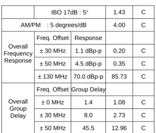
Table 2. Verification of Ka band Communications Transponder Performance
Specification Verified Value
Compli- ance Noise Figure : < 4.07 dB 3.33 C Saturated output : > 17.7 dBW @EOL 19.68 C
< -45dBW/4 KHz No spur C In-band
Spurious
Output < -40dBW/1MHz No spur C
< -50dBW/4 KHz -74.34 C LO
Harmonic
IMD < -40dBW/1MHz -74.34 C
< -60 dBW/4 KHz No spur C Out-of-
band Spurious
Output
< -50dBW
@ 40.8 ~ 41.4 GHz No spur C
± 7 ppm / life ±0.42 C Frequency
Conv.
Stability ± 15 ppm / 24hours ±0.04 C IBO 3dB : -9dB -8.77 NC Amplitude
Linearity IBO 17dB : -24dB -24.53 C IBO3dB : 37° 33.83 C Total
Phase
Shift IBO 10dB : 17° 11.58 C
IBO 17dB : 5° 1.43 C AM/PM : 5 degrees/dB 4.00 C
Freq. Offset Response
± 30 MHz 1.1 dBp-p 0.20 C
± 50 MHz 4.5 dBp-p 0.35 C Overall
Frequency Response
± 130 MHz 70.0 dBp-p 85.73 C Freq. Offset Group Delay
± 0 MHz 1.4 1.08 C
± 30 MHz 8.0 2.73 C Overall
Group Delay
± 50 MHz 45.5 12.96 C
Some parameters do slightly not meet the required values, but they can be treated as minor non-compliant matters because it is not expected to affect the overall payload system performances.
In order to measure the RF performances of transponder, the EGSE (electrical ground support equipment) is used and all parameters are tested automatically by EGSE. A sample of EGSE test result printed out is shown in Figure 4.
Fig. 4 A Sample of Test Results from EGSE (Amplitude Response and Group Delay)
Ⅴ. Conclusion
The Ka band communications transponder for COMS has been developed by ETRI. The measured performance shows that the transponder was verified to meet all the requirements for COMS.
It also shows good agreements with the calculated performances, so the validity of the design method
was verified well.
It is expected that the environment test as a STEP-3 activities will be performed based upon this evaluation results as part of the near term activities.
It is to be a valuable data base for future anomaly investigations in spacecraft test as well as in-orbit test.
Acknowledgments
This work has been funded by the Korea Communications Commission, Republic of Korea since 2003. The authors would like to thank the government members for their funding and sincere support.
Reference
[1] Y. M. Lee, J. W. Eun, S. P. Lee, " Conceptual Design of the Ka band Communication Payload for Communication, Oceanographic, and Meteorological Satellite (COMS)", The International Conference on Advanced Communication Technology, Vol. 1, ICACT, Phoenix Park, pp. 84-85. , Feb. 2004
[2] Jin-Ho Jo, In-Kwon Ju, Seong-Pal Lee,
“Development of Onboard Switch for Multi- beam Satellite Communication”, 24th AIAA International Communications Satellite Systems Conference, San Diego, California, June 2006[AIAA 2006-5449]
[3] Y. M. Lee, S. P. Lee, " DESIGN OF THE KA BAND ON-BOARD SWITCHING TRANSPONDER FOR SATCOM SYSTEM”, Ka and Broadband Communications Conference, Vol. 1, Vicenza, Italy, Oct. 2004, pp.509-517.
U저 자
이 용 민(Yong-Min Lee) 정회원
1999년 2월: 광운대학교 전자공학과 공학박사 1999년 12월: KIST 위촉선임
연구원
2000년 12월:(주)인오시스템 기술연구소 연구소장 2001년 2월∼현재: 한국전자 통신연구원 위성탑재시스템 연구팀 선임연구원
<관심분야> 통신탑재체 시스템 설계 및 전자기장 해석
이 성 팔(Seong-Pal Lee) 정회원 1990년 6월: Polytechnic Institute of New York 전자공학과 공학박사 1995년 4월: Matra Marconi
Space 및 Lockheed Martin 파견연구원 1980년 4월∼현재: 한국전자
통신연구원 위성탑재시 스템 연구팀 책임연구원
<관심분야> 통신위성 시스템