This is an Open-Access article distributed under the terms of the Creative Commons Attribution Non-Commercial License(http://creativecommons.org/licenses/by-nc/3.0) which permits unrestricted non-commercial use, distribution, and reproduction in any medium, provided the original work is properly cited.
자동차 엔진룸용 전장품 유무연 솔더 접합부의 열화특성
김 아 영*․홍 원 식*,†
*
전자부품연구원 부품소재물리연구센터
Degradation Characteristics of Eutectic and Pb-free Solder Joint of Electronics mounted for Automotive Engine
A Young Kim* and Won Sik Hong*
,
†*Components & Materials Physics Research Center, Korea Electronics Technology Institute, Seongnam-si 463-816, Korea
†Corresponding author : [email protected]
(Received June 16, 2014 ; Revised June 23, 2014 ; Accepted June 24, 2014)
Abstract
Due to environmental regulations (RoHS, WEEE and ELV) of the European Union, electronics and automotive electronics have to eliminate toxic substance from their devices and system. Especially, reliability issue of lead-free solder joint is increasing in car electronics due to ELV (End-of-Life Vehicle) banning from 2016.
We have prepared engine control unit (ECU) modules soldered with Sn-40Pb and Sn-3.0Ag-0.5Cu (SAC305) solders, respectively. Degradation characteristics of solder joint strength were compared with various conditions of automobile environment such as cabin and engine room. Thermal cycle test (TC, -40 ℃ ~ (85 ℃ and 125 ℃), 1500 cycles) were conducted with automotive company standard. To compare shear strength degradation rate with eutectic and Pb-free solder alloy, we measured shear strength of chip components and its size from cabin and engine ECU modules. Based on the TC test results, finally, we have known the difference of degradation level with solder alloys and use environmental conditions. Solder joints degradation rate of engine room ECU is superior to cabin ECU due to large CTE (coefficient of thermal expansion) mismatch in field condition. Degradation rate of engine room ECU is 50~60% larger than cabin room electronics.
Key Words : Automotive, Solder joint, Degradation, Failure mechanism, Electronic control unit (ECU) ISSN 1225-6153 Online ISSN 2287-8955
1. 서 론
전자제품 및 자동차 전장품에 사용되는 물질에 대해서 RoHS (restriction of the use of hazardous sub- stances), WEEE (waste electrical and electronic equipment) 및 ELV (End-of-Life Vehicle)등 유럽 연합의 규제가 증가하고 있다. 이러한 환경 규제들로 인해 1990년도부터 2006년까지 전자 제품의 Sn-Pb 유연솔더를 적용한 공정 제어 및 안정적인 신뢰성을 고 려하여 무연 솔더 합금 개발이 주를 이루었다. 2016년 까지 자동차 전장품에 Pb사용 규제가 진행됨에 따라 Pb-free 적용기술 개발이 요구되고 있는 실정이다
1-3).
현재 전자제품에 무연솔더는 일반적으로 적용되고 있으 나, 자동차 전장품의 경우 무연솔더 적용이 개발 초기 단계이다.
자동차에 장착된 전장제품의 필드 사용 시 사용 환경 의 온도는, 실내 전장품이 -40~85 ℃ 이며, 엔진룸이 -40~125 ℃ 이다. 이러한 사용 환경 중 발생되는 고 온과 저온의 온도편차가 실내 전장품 (125 ℃) 보다 엔진룸 전장품 (165 ℃)이 더 크기 때문에 솔더 접합 부에 큰 스트레스를 인가하게 되는 주요 원인으로 생각 된다
4-6). 선행 연구들에 의해 솔더의 파괴원인이 사용 환경의 온도편차에 의한 열-기계적 피로파괴가 주요원 인이 되어 솔더 접합부의 균열을 유발하는 것으로 알려 져 있다. 이러한 선행 연구 결과로 볼 때, 실내보다 엔
연 구 논 문
Solder Alloy Sn-3.0Ag-0.5Cu Sn-40Pb
PCB
Material FR-4, Tg = 145℃
Surface
finish OSP Sn-40Pb
Test components
0402, 0603 and 1206 Chip resistor 0603, 1206, 3225 Chip capacitor, Al Electrolyte
Capacitors
QFP, SOP, BGA and Transistor (*The unit of chip components: inch)
(a) (b)
Fig. 1 Photographs of PCU module soldered with (a) Sn-40Pb and (b) SAC305
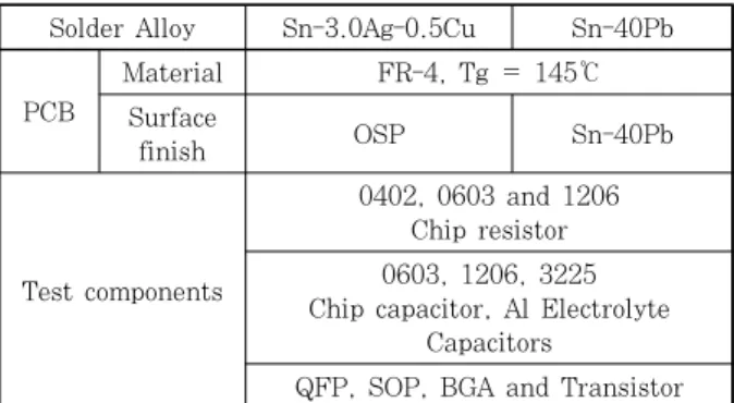
Table 1 PCB, solder materials and test components of engine control ECU module
Solder Alloy Sn-3.0Ag-0.5Cu Sn-40Pb
PCB
Material FR-4, Tg = 145℃
Surface
finish OSP Sn-40Pb
Test components 1608 and 3216 Chip resistor, 1608 Chip capacitor, QFP
Table 2 PCB, solder materials and test components of cabin control ECU module
(a) (b)
Fig. 2 Photographs of cabin electronics module soldered with (a) Sn-40Pb and (b) SAC305 진룸 전장품의 솔더 접합부의 파괴가 더 빠르게 진행
될 것을 예상 할 수 있다.
따라서 본 연구는 실제 자동차에 적용되고 있는 유연솔더 (Sn-40Pb) 및 무연솔더 (Sn-3.0Ag-0.5Cu, SAC305) 를 사용한 엔진제어 모듈 (power control unit, PCU) 을 제작한 후 사용 환경에 따른 솔더 접합부의 내구신 뢰성을 검증하였다. 또한 솔더 접합부의 주요 고장 메 커니즘을 도출하였다. 이를 기반으로 고온 환경 조건에 서 SAC305 무연솔더의 적용 가능성에 대한 비교분석 을 수행하였다.
2. 실험 방법
본 연구에 사용된 ECU 모듈은 유리천이온도 (T
g) 145 ℃, FR-4 재질의 인쇄회로기판 (printed circuit board, PCB)을 사용하여, Table 1과 Fig. 1에서와 같이 Sn-40Pb 유연솔더 및 SAC305 무연솔더를 사용 한 PCU 모듈을 제작하였다. 적용된 PCB 표면처리 재 료로, 유연솔더 적용 기판은 Sn-40Pb, 무연솔더 적용기 판은 OSP (organic solderability preservative) 표 면처리 하였다. Table 2와 Fig. 2는 실내전장품 ECU 모듈을 Sn-40Pb 유연솔더 및 SAC305 무연솔더를 사용하여 각각 제작하였다. 사용 환경조건에 따른 솔더
접합부의 접합강도 열화특성 비교를 위해, 열충격시험 (thermal cycles test, TC)을 실차 시험조건에 따라 실험하였다. 열충격시험 조건은 -40~125 ℃, 각 온도 에서 유지시간 10 min 조건으로 1500 cycles (90 min/
cycle) 동안 실험을 진행하였다. 실험조건은 보드의 온 도를 측정하여 온도 프로파일을 도출, 적용하였다. 또한 동작상태시 전원 인가에 의한 영향을 고려하기 위해, 시 험 중 1.5 V 구동전압을 인가하였으며, 전류의 변화를 연속적으로 측정하였고, 시험 전/중/후 전류의 변화로 고장 유무를 확인하였다. 솔더 접합부의 열화특성 분석 을 위해 X-선 비파괴분석 (X-Ray non-destructive microscope), 광학현미경 및 주사전자현미경(ESEM) 을 사용하였다. 본딩시험기 (Dage 4000 모델)를 사용 하여 부품의 솔더 접합부 전단강도 및 45도 리드 인장 강도를 측정하였다.
사용 환경조건에 따른 열화특성 비교를 위해, 일반 전자 제품을 -40~85 ℃, 유지시간 10 min에서 1500 cycles 동안 열충격시험을 진행한 후, 각각의 유무연 솔더 접 합부의 접합강도를 비교분석 하였다.
3. 결과 및 고찰
3.1 엔진룸 전장품의 솔더 접합부 분석
동작시험 조건에서 각각의 시험환경에서 계산된 전류
의 값과 실제 측정된 평균 전류 값이 유사하였고, 시험
전후 구동전류의 변화가 없었던 것으로 보아, 모듈의 고
장은 발생하지 않은 것으로 판단된다. 따라서 솔더 접
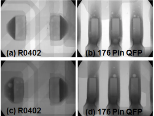
Fig. 3 X-Ray non-destructive images of solder joints:
(a, b) Sn-40Pb and (c, d) SAC305
10
R0402
Components Void contents(%) 8
6
4
2
0
R0603 R1206 C0603 C1206 Al-Cap 3.9
2.8 2.4 6.0 6.2
3.4
0.6 0.6 1.4
0.5 6.9 7.0 SAC305
Sn-40Pb
(a)
10
Void contents(%) 8 6
4
2
0
ASIC-44pin ASIC-32pin
General-IC IC-68pin
IC-20pin Mocroproces...
Connector
Components
SAC305 (b)
Sn-40Pb
2.0 2.3 4.7 4.3
2.7 2.8 2.7 6.1
7.4
1.6 2.8
5.2
2.1
0.3
(a)
Fig. 4 Mean void contents (%) of Sn-40Pb and SAC305 solder joints with (a) chip resistor, chip capacitor and (b) QFP after as-reflowed soldering
SAC305
Shear strength (kgf)
180 160 140 120 100 80 60 40 20 0
R0402 R0603 R1206 C0603 C1206 Al-Cap 16.4 13.0
43.8 39.3
103.7103.5
30.8 27.4 52.5 51.9
136.5142.1 Sn-40Pb
Fig. 5 Shear strength comparison of Sn-40Pb and SAC305 solder joints after as-reflowed soldering
0
‐20
‐40
‐60
‐80
‐100 -65.5
-29.1 -29.1
-69.6
-44.3 -44.3
-76.8
-68.9 -68.9
(a)
(b) SAC305 Sn-40Pb SAC305 Sn-40Pb SAC305 Sn-40Pb
TC fail TC good Shear strength degradation rate (%)
-46.1
-21.5 -21.5 -30.2
-50.4 -50.4 -14.1
-35.1 -35.1
R0402 R0603 R1206
SAC305 Sn-40Pb SAC305 Sn-40Pb SAC305 Sn-40Pb
C0603 C1206 Al-Cap
TC fail TC good 0
‐20
‐40
‐60
‐80
‐100 Shear strength degradation rate (%)
Fig. 6 Shear strength variation (%) of solder joints after each reliability tests : (a) chip resistors and (b) chip capacitor and surface mounte type aluminium electrolytic capacitor 합부의 100% 균열발생으로 인한 전류변화가 없으며,
균열 발생이 접합면 전체에 진전된 것이 아님을 예상 할 수 있다.
Fig. 3과 Fig. 4는 유무연 솔더의 각 부품별 평균 보이드 함유율이 8% 이내 이며, 이는 자동차 환경에서 의 합격조건이 25% 내외 인 것을 감안할 때, 양호한 솔더 접합부의 형성한 것을 확인하였다.
Fig. 5는 솔더 별 초기 전단강도 값이다. 유무연 솔 더의 유사한 전단 값을 보였으며, 부품의 크기가 클수
록 전단 강도의 값이 높게 측정 되었다. 환경시험 후 성능검사 (functional test)를 진행하였고, 기능고장 발생 유, 무에 따른 동일 부품의 솔더 접합강도 변화율 을 측정하였다. 초기 대비 시험 후 접합강도를 비교하 여 솔더 접합부의 열화비율을 비교할 수 있었다. Fig.
6와 같이, 무연솔더가 유연솔더 보다 평균 약 28%의 접합강도 변화율이 더 크게 나타났으며, 이것은 무연솔 더 접합강도의 열화 정도가 유연솔더에 비해 더 큰 것 으로 나타났다. 부품 크기가 큰 R1206 칩 저항기의 초기 대비 접합강도 변화율이 약 76% 감소되어 가장 크게 나타났다.
Fig. 7과 Fig. 8은 유무연 솔더 접합부의 계면을 분
석한 SEM 사진이다. 균열이 발생된 위치를 분류하면
칩과 솔더의 균열, 도금 층 박리 및 솔더 모재로부터의
균열 발생과 진전으로 분류된다.
(a) (b)
(c) (d)
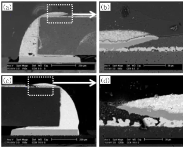
Fig. 7 Cross-sectional SEM micrographs of solder joints cracks and chip crack after reli- ability tests: (a, b) 1206 chip capacitor soldered with Sn-40Pb after TC, (c, d) 3225 chip capacitor soldered with SAC305 after TC
(a)
(c)
(b)
(d)
Fig. 8 Cross-sectional SEM micrographs of electro- plating layer lift-off after reliability tests:
(a, b) 1206 chip capacitor soldered with Sn- 40Pb after TC, (c, d) 3225 chip capacitor soldered with SAC305 after TC
Sn-40Pb
Voldcontents (%)
10.0
8.0
6.0
4.0
2.0
0.0
Void contents of solder joints
SAC305 Solder Alloys
Fig. 9 Average voids content (%) of solder joints of cabin electronics after as-reflowed soldering
Shear strength (kgf)
90
60
30
0 30.9
27.1 64.7
59.0
12.6 11.3 SAC305 Sn-40Pb
R3216 C1608 QFP
Fig. 10 Shear strength comparison of Sn-40Pb and SAC305 solder joints with electronic compo- nents after as-reflowed soldering
열충격시험에서 전류측정 시 관찰되지 않았으나, Fig. 7 (a~d)와 같이 솔더 접합부에서 균열이 발생된 것을 확 인하였다. 솔더 접합부의 균열이 100% 발생된 경우 성능측정 등으로 발견할 수 있으나, 균열이 완전히 진 전되지 않은 경우, 성능측정 중 기능이상이 검출되지 않는 한계를 나타내었다. 따라서 성능측정 이외에 표면 에 균열이 관찰되는 경우, 단면분석을 통한 균열발생 여부를 관찰 할 필요가 있을 것으로 보인다. 이러한 솔 더 접합부의 균열 발생은 전장품 사용 환경의 고온과 저 온의 온도 편차가 클 경우, 부품, 솔더 및 기판의 CTE (coefficient of thermal expansion) 차이가 더 크게 발생되어 균열이 크고 진전된 양상으로 보여 진다
7).
유무연 솔더 적용 모듈의 내구 신뢰성시험에서 Fig.
8과 같이 칩 부품의 도금 층 박리가 발생한 것을 관찰 할 수 있었다. 이러한 도금 층 박리현상은 솔더 접합부 의 문제가 아닌 부품의 도금 밀착성의 문제로 생각된 다. 자동차용 전장품의 무연솔더를 적용할 경우, 반드 시 고려되어야 할 부분으로 생각된다.
3.2 실내 전장품과 솔더 접합부 분석
Fig. 9는 실내 전장품의 유무연 솔더 접합부에 대한 보이드 함유율 측정결과이며, 각각 5% 미만의 함유율 을 나타내어 양호한 접합 상태임을 알 수 있었다.
Fig. 10은 유무연 솔더의 초기 전단 강도 값을 나타 낸 그래프이다. 유사한 값을 나타내며 C1608의 전단강 도가 가장 큼을 확인 하였다.
Fig. 11은 열충격시험 1500 cycles 시험 후 칩 저
항기의 접합강도 변화율 (%) 측정 결과이다. 유연솔더
의 접합강도 변화율이 무연솔더 보다 다소 크게 나타났
다. C1608을 제외한 다른 부품에서는 유, 무연솔더 접
합강도 열화는 유사한 것으로 판단된다. 칩 부품의 경
우 크기가 큰 칩 캐패시터의 변화율이 가장 크게 나타
났다. 이것은 솔더 접합부의 열화에 부품의 크기가 일
0
‐10
‐20
‐30 -5.5
-8.1
-4.2
-24.9
SAC305 Sn-40Pb SAC305 Sn-40Pb
Shear strength degradation rate of solder joints(%)
R3216 C1608
Fig. 11 Shear strength variation (%) of Sn-40Pb and SAC305 solder joints after 1500 thermal cycles
(a)
(b)
Crack Initiation Ag3Sn
Cu6Sn5
(a)
(b)
Crack Initiation Ag3Sn
Cu6Sn5
Fig. 12 Cross-sectional SEM micrographs of (a) SAC305 solder joints and (b) magnified view of (a) after 1500 thermal shock cycles
Use
environment Solders Degradation rate (%)
Engine Sn-40Pb -68.9
SAC305 -76.8
Cabin Sn-40Pb -16.8
SAC305 -11.8
Shear strength of chip resistor solder joint
Shear strength (kgf)
120
100
80
60
40
20
0
0cycles 1500cycles
Thermal shock cycles
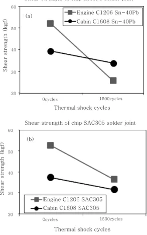
Engine R1206 Sn-40Pb Engine R1206 SAC305 Cabin R1608 Sn-40Pb Cabin R1608 SAC305
Fig. 13 Shear strength degradation of chip resistors soldered with Sn-40Pb and SAC305 solder for engine room and cabin electronics after 1500 thermal shock test
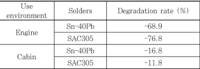
Table 3 Comparison of degradation rate of chip resistors of Sn-40Pb and SAC305 solder joint strength between engine and cabin ele- ctronics for vehicles
부 영향을 미치고 있음을 알 수 있으며, 부품의 열화 판단을 위해서 접합강도를 측정하는 경우, 큰 사이즈의 부품을 중심으로 측정하는 것이 필요할 것으로 생각된다.
SAC305 무연솔더를 사용하여 접합된 C1608의 SEM 단면분석 결과는 Fig. 12과 같다. 실내 전장품용 ECU 모듈은 엔진룸 ECU와 동일하게 솔더 접합부의 필렛 (fillet) 부위에서 균열이 발생되어 솔더의 모재 내부로 진전되고 있음을 알 수 있다. 솔더 필렛 부위에서 균열 이 시작되는 것은 전형적인 열-기계적 반복 스트레스에 의해 피로균열이 발생된 것임을 알 수 있다.
8)또한 솔 더 모재에서는 Cu
6Sn
5및 Ag
3Sn IMC가 형성된 것을 관찰 할 수 있었다. 솔더링 초기 SAC305 무연솔더 접 합부의 접합강도가 더 큰 것이 모재에 형성되는 이러한 Ag
3Sn IMC의 미세분산에 의한 것이며, TC Cycle이
진행됨에 따라 IMC의 조대화로 인한 접합강도가 저하 되는 것은 이미 잘 알려진 결과이다.
3.3 엔진룸과 실내 전장품의 솔더 접합부의 접합강도 비교
엔진룸과 실내 전장품의 솔더 접합강도 비교 결과는 다음의 Fig. 13, 14와 같다. 동일한 칩이 아닌 유사 크 기의 칩 부품의 접합강도를 상대 비교 하였으며, 이것 을 식 (1)과 같이 열화율 (degradation rate, %)로 계산하였으며, 그 결과는 다음의 Table 3과 4와 같다.
엔진룸 사용조건인 경우, Sn-40Pb 솔더 접합부의 접 합강도 열화율이 -68.9% 인데 반해, SAC305는 약 -76.8%로 나타났다. 엔진룸 사용 환경 보다 상대적으 로 덜 가혹한 실내전장 조건에서는 유무연 솔더의 접합 강도 열화율이 각각 -16.8%와 -11.8%로 나타나 유사 한 수준으로 판단된다. 이러한 열화율은 사용되는 전자 부품의 종류에 따라 그 비율이 다소 편차를 나타내고 있 으나, 전체적인 열화되는 경향을 비교한다면 가혹한 사 용 환경 조건에서 사용되는 SAC305 무연솔더의 열화 경향이 유연솔더 보다 더 크게 나타난 것을 알 수 있다.
Use
environment Solders Degradation rate (%)
Sn-40Pb Engine -50.4
Cabin -18.6
SAC305 Engine -30.2
Cabin -8.6
0cycles 1500cycles
Thermal shock cycles Shear strength of chip sn40Pb solder joint
Engine C1206 Sn-40Pb Cabin C1608 Sn-40Pb 60
50
40
30
20
Shear strength (kgf) (a)
(b)
Shear strength of chip SAC305 solder joint
0cycles 1500cycles
Thermal shock cycles Engine C1206 SAC305 Cabin C1608 SAC305 60
50
40
30
20
Shear strength (kgf)
Fig. 14 Shear strength degradation of chip capacitors of engine room and cabin electronics after thermal shock test, 1500 cycles : (a) Sn- 40Pb and (b) SAC305
Table 4 Comparison of degradation rate of chip capacitors of Sn-40Pb and SAC305 solder joint strength between engine and cabin electronics for vehicles
×
(1)
Fig. 13은 칩 저항기의 솔더 접합부 열화특성을 나 타낸 그래프이다. 유무연솔더 모두 엔진룸 사용조건에 서 시험한 솔더 접합부의 접합강도가 실내 전장조건 보 다 더 크게 열화되는 것으로 나타났다. 열화되는 비율
을 Table 3과 같이 유무연 솔더에 따라 비교하면, 엔 진룸 사용조건이 차량의 실내 조건보다 솔더 접합부의 열화율이 약 60% 이상 빠르게 진행되었다.
Fig. 14는 칩 캐패시터의 각 솔더 접합부 전단강도 값을 나타낸 그래프이다. Table 4는 사용 환경 온도에 따른 솔더 조성별 칩 캐패시터의 접합강도 열화율을 비교한 결과이다. Sn-40Pb의 경우, 엔진룸 조건은 -50.4% 열화 된 반면, 실내 전장품은 -18.6% 감소되 었다. 또한 SAC305 무연솔더에서는 엔진룸 조건이 -30.2% 감소된 반면, 실내전장 조건에서는 -8.6% 감 소된 것으로 나타났다. 이러한 결과로 볼 때, 동일한 조성의 솔더인 경우, 엔진룸의 접합강도 열화율이 실내 전장품 보다 약 20~30% 정도 더 크게 나타났다. 또 한 엔진 전장품의 경우, 사용 환경조건이 열적으로 더 가혹하기 때문에 솔더 접합부의 열화정도가 실내 전장 품 사용조건에 비해 가속되는 것을 알 수 있다. 결국 가혹환경에 사용되는 엔진 전장용 무연솔더의 개발이 필요한 것으로 판단된다.
4. 결 론
Sn-40Pb 및 SAC305 유무연 솔더를 적용하여 자동 차 전장품용 ECU 모듈을 제작한 후 실내 및 엔진룸 사용 환경조건에 따른 솔더 접합부의 열화특성을 비교 분석 하였으며, 그 결과는 다음과 같다.
1) 엔진룸 사용조건인 경우, Sn-40Pb와 SAC305 솔더의 초기 접합강도는 유사하였다. 그러나 열충격시험 1500 Cycles 후 접합강도를 비교한 결과, SAC305 무 연솔더의 접합부 열화가 Sn-40Pb 유연솔더 보다 약 10% 정도 더 크게 발생한 것을 알 수 있었다.
2) 자동차 전장품의 사용 환경에 따른 솔더의 접합강 도 열화율을 비교한 결과, 솔더 접합강도의 변화율이 실내 전장환경 보다 엔진룸 조건에서 50~60% 정도 더 크게 나타났다. 이것은 엔진룸 사용조건의 온도편차 가 165 ℃, 실내 전장품이 125 ℃로써, 약 45 ℃의 온도 편차가 발생하며, 이로 인해 솔더 접합부의 열-기계적 피로파괴가 더 가속되는 것으로 사료된다.
3) 유무연 솔더 접합부에서 모두 균열이 관찰되었으
며, 이 균열은 저온과 고온의 온도편차에 의한 CTE 차
이로 인해 발생된 것으로 판단된다. 또한 CTE 차가 더
큰 엔진룸의 솔더 접합부 균열이 더 길게 진전된 것으
로 관찰되었다. 따라서 자동차 엔진 전장품용 무연화
대응을 위해 고온에서 우수한 열적 피로특성을 갖는 무
연솔더의 개발이 필요하다.
Reference
1. Katsuaki Suganuma, Seong-Jun Kim, and Keun-Soo Kim : High-Temperature Lead-Free Solders : Properties and Possibilities, The Minerals, Metals & Materials Society 61-1 (2009), 64-71
2. C.M. CHUANG, T.S. LUI, and L.H. CHEN : The Characteristics of Vibration Fracture of Pb-Sn and Lead-Free Sn-Zn Eutectic Solders, Journal of Electronic Materials, 30-9 (2001)
3. R. Wayne Johnson, John L. Evans, Peter Jacobsen, James R. (Rick) Thompson, and Mark Christopher : The Changing Automotive Environment: High-Tempera- ture Electronics, IEEE Transactions on Electronics Packaging Manufacturing, 27-3 (2004), 164-176 4. Mi Jin Kim, Moon Il Kim, Kyu Sik Shin,Jae Pil
Jung : Lead-free Solders on the Electronics, Journal of the Microelectronics and Packaging Society, 7-4 (2000), 49-54 (in Korean)
5. G. Leen and D. Heffernan : Expanding automotive electronic systems, IEEE Computer, 35-1 (2002), 88-93 6. M. R. Fairchild, R. B. Snyder, C. W. Berlin, and D.
H. R. Sarma : Emerging substrate technologies for harsh-environment automotive electronics applications, SAE Technical Paper Series, 2002-01-1052
7. Sang-Su Ha, Jong-Woong Kim, Jong-Hyuck Chae, Won-Chul Moon, Tae-Hwan Hong, Choong-Sik Yoo, Jeong-Hoon Moon and Seung-Boo Jung : Thermo- Mechanical Reliability of Lead-Free Surface Mount Assemblies for Auto-Mobile Application, Journal of KWJS, 24-6 (2006), 21-27 (in Korean)
8. Il Ho Kim, Tae Sang Park, Se Young Yang and Soon Bok Lee : A Comparative Study of the Fatigue Behavior of SnAgCu and SnPb Solder Joints, Key Engineering Materials, 297-300 (2005) 831-836
9. Won Sik Hong, and Chul Min Oh : Degradation Behavior of Solder Joint and Implementation Technology for Lead-free Automotive Electronics, Journal of KWJS, 31-3 (2013), 22-30 (in Korean)