한수지 52(6), 702-708, 2019
702
Copyright © 2019 The Korean Society of Fisheries and Aquatic Science pISSN:0374-8111, eISSN:2287-8815
Korean J Fish Aquat Sci 52(6),702-708,2019
Original Article
서 론
종래의어군탐지기에서는주파수대역폭이매우좁은음향펄 스신호를수중으로방사하고, 어족생물로부터산란되는 어군
echo 신호를수신, 분석하여대상어류의생물학적및음향학
적정보등을탐지하여왔다(Airmar Technology Corporation,
1994). 이와같은어군탐지기에서최대의탐지성능을얻기위
해서는작동주파수와송·수파기의공진주파수가반드시일치 해야한다. 그러나, 조업해역에따라수온이변화하여송·수파 기의공진특성이변동하면어군탐지기의탐지성능, 즉송·수신 감도가급격히저하하는문제가발생한다. 또한, 일반적으로기 존의어군탐지기에서는기계적품질계수(quality factor)가매 우큰송·수파기를사용한다. 이때문에비록송·수파기에전기 적인구형펄스신호(rectangular pulse signal)를공급하더라도 해중으로 방사되는 음향펄스신호는가우시안 파형(Gaussian waveform)으로변화(distortion)되기때문에어족생물의식별 분해능이급격히저하한다. 따라서, 어군탐지기에대한어족생 물의식별분해능을향상시키기위해서는송·수파기의주파수 대역폭을확장시킬필요가있다. 이렇게하면해중으로방사되
는음향펄스신호의파형은송·수파기에공급되는전기적인구 형펄스신호의파형과거의유사한형상이된다(Lee, 2014; Lee et al., 2014). 이를통해현용의어군탐지기에서사용하고있는 송·수파기의주파수대역폭이확장되면, 해저부근에분포하는 어족생물이나군집하고있는개체어의식별분해능이향상되 고, 또한, 수심의측량정밀도등이향상된다(Lee, 2014; Lee, 2015; Lee et al., 2016, Lee, 2017). 본연구에서는이점에주목
하여현재우리나라어선에서가장많이사용하고있는 50 kHz
의샌드위치형음향변환기(sandwich type acoustic transducer) 를대상으로주파수대역폭을확장시키기위한대역통과정합 회로를설계하였다. 또한, 이정합회로를갖는음향변환기와갖 지않는음향변환기에대한송·수신성능특성을실험적으로비 교, 분석하였다.
재료 및 방법
음향변환기의 대역통과 정합회로 설계
본연구에서실험에사용한음향변환기는 Fig. 1의 (a)에나타
대역통과 정합회로를 이용한 수중음향변환기의 대역폭 확장
이대재*
부경대학교 해양생산시스템관리학부
Bandwidth Enhancement of Underwater Acoustic Transducer Using a Bandpass Matching Network
Dae-Jae Lee*
Division of Marine Production System Management, Pukyong National University, Busan 48513, Korea
The range resolution of echo sounders can be improved by enhancing the transducer bandwidth. We designed a band- pass matching network for expanding the bandwidth of a transducer by scaling in both impedance and frequency after transforming a lowpass network into a bandpass configuration for a third-order Bessel filter. We measured the effect of the Bessel matching network for a 50 kHz sandwich type transducer on the transmitting voltage response (TVR), receiving sensitivity (SRT) and figure of merit (FOM), using a chirp echo sounder system. Both the simulation and experimental results indicated that the transducer with a bandpass matching network was capable of producing a symmetrical acoustic output over a wider bandwidth (8.25 kHz) than was the transducer without a matching network (3.75 kHz). By implementing the Bessel matching network, we achieved a 120% bandwidth enhancement.
Key words: Bandwidth enhancement, TVR, Acoustic transducer, Bandpass matching network, Transfer function
*Corresponding author: Tel: +82. 51. 629. 5889 Fax: +82. 51. 629. 5885 E-mail address: [email protected]
This is an Open Access article distributed under the terms of the Creative Commons Attribution Non-Commercial Licens (http://creativecommons.org/licenses/by-nc/3.0/) which permits unrestricted non-commercial use, distribution, and reproduction in any medium, provided the original work is properly cited.
Received 11 October 2019; Revised 18 November 2019; Accepted 19 November 2019 저자 직위: 이대재(교수)
https://doi.org/10.5657/KFAS.2019.0702
Korean J Fish Aquat Sci 52(6), 702-708, December 2019
대역통과 정합회로를 이용한 수중음향변환기의 대역폭 확장 703
낸샌드위치형초음파진동자이다. 이음향변환기는티탄산바 륨(barium titanate, BaTiO3) 소자의전면과후면에각각알루 미늄재질의 head mass와철재질의 tail mass를체결하여제 작한직경 51 mm의진동자이다(Murata, 1978; Airmar, 1994;
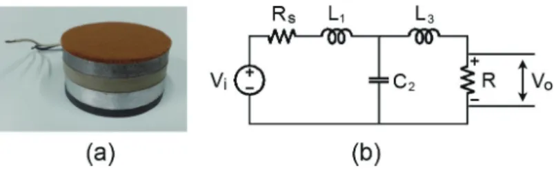
Tokin, 1999). Fig. 1의 (a)에나타낸초음파진동체는수중에서 의송·수신성능특성을측정하기위해실험전에수밀처리를하 였다. 음향윈도우(acoustic window, 두께약 5 mm)는비교적 연질의우레탄(urethane rubber, Sctchcast 2130, 3M, Austin, TX, USA)으로성형하였고, 그이외의하우징(housing)은경도 가더높은다른종류의우레탄고무(Flexane 80 Liquid 15800, Devcon, Danvers, MA, USA)로몰딩하였다. 이때, 음향윈 도우로부터발생하는후면방사의영향을저감시키기위해 tail mass 표면에두께 3 mm의콜크층(cork layer)를부착하였다. Fig. 1의 (a)에나타낸음향변환기의 BVD (Butterworth-van dyke) 등가회로를포함하는 3차저역통과정합회로는 Fig. 1 의 (b)와같다(Coates and Mathams, 1988; Radmanovic and Mancic, 2004).
본연구에서는 Fig. 1의 (b)에나타낸 Bessel 저역통과필터함 수를이용하여대역통과정합회로를설계하였다. Fig. 1에나 타낸 Bessel 저역통과 ladder network에대한각전기소자의 값은송신부의출력임피던스 Rs가음향변환기의방사임피던 스 R과같다고가정하여구하였다. 즉, Rs≈R=1이라고가정하 였을때, L1=0.3374, C2=0.9705, L3=02.2034이었다(Bowick, 1982; Winder, 2002). 한편, Fig. 1에나타낸음향변환기의 3차 저역통과정합회로를 6차대역통과정합회로로변형시켜나타 내면 Fig. 2와같다(Coates and Mathams, 1988; Coates, 1991;
Stansfield, 1991; Radmanovic and Mancic, 2004). 이때, Fig.
2의 ladder network에대한전기소자값들은 Fig. 1의각 branch 에대한전기소자값을대역통과회로망으로의주파수변환과 임피던스 스케일링(scaling)을 통해구하였다(Bowick, 1982;
Hong and Lancaster, 2001). 즉, Fig. 2에나타낸각 ladder 회로 의인덕턴스(inductance) L과커패시턴스(capacitance) C값은 다음식에의해구하였다(Hong and Lancaster, 2001; Radma- novic and Mancic, 2004).
RL=R·β L1b= L∆f1·β
C1b= ∆f ωs2·L1·β L2b= ∆f ·βC2·ωs2
C2b= C2 -Co
∆f·β L3b= L∆f3 ·β
C3b= ∆f ωs2·L3·β
여기서, β는임피던스 스케일링 상수, ∆f는정합회로의 대 역폭이다. 또한, Co는 음향변환기의 제동용량(clamped ca- pacitance), fs는음향변환기의직렬공진주파수(ωs=2πfs)이다 (Coates and Maguire, 1989).
Fig. 1의 (a)에나타낸음향변환기의 BVD 등가회로에대한각 전기소자의측정치는 Co=0.0048 μF, L3b=18.3 mH, C3b=0.545 nF, RL= 228 Ω이었다. 또한, Fig. 1의 (b)에나타낸 3차저역 통과 정합회로를 Fig. 2의 6차 대역통과 정합회로로 변형시 켜나타낸각전기소자의이론계산치는각각 L1b=2.799 mH, C1b=3.558 nF, L2b=64.32 μH, C2b=0.15 μF이었다. 그러나, 본 연구에서는반복적인실험을통해각각 L1b=2.6 mH, C1b=3.6 nF, L2b=65 μH, C2b=0.15 μF의값을갖는실험적인대역통과 정합회로를설계하여송·수신성능특성을측정하였다. Fig. 1. (a) Photograph of sandwich type acoustic transducer used in this study, (b) Third-order lowpass equivalent circuit of the matched transducer.
Fig. 2. Sixth-order bandpass matching network with ladder filter representation of acoustic transducer.
704 이대재
한편, Fig. 2의 ladder 필터소자로나타낸대역통과정합회로 를포함하는음향변환기의송파모드에대한전달함수(transfer function)는입력신호를 Vi, 출력신호를 Vo라할때, 다음식에 의해구할수있다(Coates and Mathams, 1988; Coates, 1991).
Vo
= Ks3 ……… (1)
Vi As6+ Bs5+Cs4+Ds3+Es2+Fs+G A=1
B=Rs/L1b+RL/L3b Cbb=C2b+Co
C1=(L1b+L2b)/L2b+Cbb/C1b C2=C1/(L1b*Cbb)
C =C2+ (RL*Rs)/(L3b*L1b)+1/(C3b*L3b) K = RL/(L1b*L3b*Cbb)
D =Rs/(L1b*L2b*Cbb)+K*C1+Rs/(L1b*L3b*C3b) E1=1/(L1b*L2b*C1b*Cbb)
E2=(RL*Rs)/(L1b*L2b*L3b*Cbb) E3=C1/(L1b*L3b*C3b*Cbb) E =E1+ E2+E3
F =RL/(L1b*L2b*L3b*C1b*Cbb)+Rs /(L1b*L2b*L3b*C3b*Cbb) G =1/(L1b*L2b*L3b*C1b*C3b*Cbb)
음향변환기의 주파수 응답특성의 측정
본연구에서제작한샌드위치형음향변환기에대한수중에서 의전기적인 임피던스는정밀 LCR meter (7600, QuadTech, USA)를사용하여 측정하였다. 또한, 음향변환기의송파응답 특성(transmitting voltage response, TVR)과수파응답특성(re- ceiving sensitivity, SRT)은대형실험수조(L×B×D, 5×6×5 m)에서측정하였다(Lee, 2017).
실험에서는 Fig. 3의 chirp 신호(펄스폭 1.25 ms)를미리생성 하여임의파형발생기(33120A, HP, Spring, TX, USA)의메모 리에저장시켜놓은후, 필요에따라이것을호출하여사용하였 다(Dong and Cui, 2012). 송·수신응답특성의측정에서는임 의파형발생기로부터발생시킨 Fig. 3의전압 400 mV, 주파수 대역 1-80 kHz의 chirp 신호를전력증폭기(2713, B&K, Den- mark)에서증폭한후, 이신호를대역통과정합회로(bandpass matching network)를경유하여음향변환기에공급하였다. 음 향변환기에서 방사되는 송신펄스신호는 수중청음기(model 8100, B&K, Denmark)를사용하여수신한후, Measuring am- plifier (model 2610, B&K, Denmark)에서증폭하고, 이증폭된
(a)
(b)
(a)
(b)
(a)
(b)
(a)
(b)
Fig. 3. Time-frequency response characteristic of chirp pulse sig- nal at the electrical terminal of sandwich type acoustic transducer.
(a)
(b)
(a)
(b)
(a)
(b)
(a)
(b)
Fig. 4. Magnitude (a) and phase characteristics (b) of the input electric impedance for sandwich type acoustic transducer in water without (dot line) and with a bandpass matching network (solid line).
대역통과 정합회로를 이용한 수중음향변환기의 대역폭 확장 705
신호를디지털오실로스코프(DS1530, EZ, Korea) 및 FFT 분 석기(3525, AND, Japan)에수록하였다. 이와같이수록한출력 신호를이용하여음향변환기의송파및수파응답특성를구하였 다. 한편, 본연구에서는 Fig. 1에나타낸음향변환기를 2 set 제 작하여하나는송파용으로, 다른하나는수파용으로사용하여 수파감도특성을구하였다.
결과 및 고찰
샌드위치형 음향변환기의 임피던스 특성
본연구에서제작한 Fig. 1의 (a)에나타낸샌드위치형수중음 향변환기에대한입력전기임피던스의주파수응답특성을나 타낸결과는 Fig. 4와같다. Fig. 4에서 (a)는임피던스의진폭특 성이고, (b)는임피던스의위상특성이다. 또한, Fig. 4에서점선
은정합회로가없는음향변환기에대한임피던스의주파수응 답특성이고, 실선은 Fig. 2의 Bessel 대역통과정합회로를내 장하고있는음향변환기에대한임피던스의주파수응답특성 이다. 먼저, 정합회로가없는수중음향변환기의경우, 그공진 (직렬공진) 및반공진(병렬공진) 주파수는각각 50.01 kHz와
53.76 kHz에출현하였고, 이들공진주파수에대한임피던스
진폭은각각 266.9 Ω과 1535.9 Ω이었다. 또한, 정합회로가없 는경우에는 33.65 kHz에서도진동성분이출현하였고, 그임피 던스진폭은 797.05 Ω이었다. 본연구에서는 33.65 kHz 부근에 나타나는임피던스의주파수응답은고려하지않았다. 즉, Fig.
4의 50.01 kHz 부근에출현하는직렬공진응답특성에대한주 파수대역을확장시키기위한정합회로만을설계, 제작하여실 험적으로분석, 고찰하였는데, 그결과는 Fig. 4의실선과같다. Fig. 4에서 Bessel 대역통과정합회로가접속된수중음향변환 기에서는 46.51 kHz, 50.43 kHz 및 55.39 kHz에서임피던스진 폭이최소가되는공진응답특성이출현하였는데, 이들주파수 에서의임피던스진폭은각각 95.0 Ω, 239.2 Ω 및 91.1 Ω이었 다. 한편, 임피던스진폭이최대가되는반공진응답특성은각 각 49.4 kHz와 52.2 kHz에서출현하였는데, 이들주파수에서 의임피던스진폭은각각 274.8 Ω과 315.5 Ω이었다. Fig. 4에서
3개의공진주파수와 2개의반공진주파수에대한평균적인임
피던스의차는 153.4 Ω이었다. 본연구에서는정합회로가없는 경우에대한공진주파수(50 kHz)를중심으로 -3 dB 구간에서
±4 kHz의주파수대역폭을생성함으로써약 6 정도의기계적
품질계수(quality factor, Q)를실현하고자하였다. 샌드위치형 음향변환기의 송파감도 특성
Fig. 1의샌드위치형음향변환기에 Fig. 3의전기적인 chirp 신 호를공급하여수중으로음향펄스신호를송출한후, 음축상약
1.2 m 거리에설치한수중청음기로부터출력되는펄스신호의
(a)
(b)
(a)
(b)
(a)
(b)
(a)
(b)
Fig. 5. Time-frequency response characteristics of the transmitted chirp pulse signal for sandwich type acoustic transducer without (a) and with a bandpass matching network (b).
(a)
(b)
(a)
(b)
(a)
(b)
(a)
(b)
Fig. 6. Frequency response characteristics of the relative transmit- ting voltage response (TVR) for sandwich type acoustic transducer without (dot line) and with a bandpass matching network (solid line).
706 이대재
시간-주파수송신응답특성을구한결과는 Fig. 5와같다. Fig. 5 에서 (a)는정합회로가없는음향변환기의시간-주파수송신응 답특성이고, (b)는 Bessel 대역통과정합회로를내장한음향변 환기에대한시간-주파수송신응답특성이다. Fig. 5의 (a)와 (b) 에서시간응답파형은각각위쪽에나타내었고, 주파수응답스 펙트럼은각각왼쪽에 나타내었다. 이들주파수응답스펙트럼 에서진폭은최대값을 0 dB로정규화하여 0-30 dB 범위에대하 여나타내었다. Fig. 5의 (a)에서정합회로가없는음향변환기에 대한음향펄스신호의송신주파수응답은 50.25 kHz에서가장 강하게출현하였다. 이주파수를기준으로측정한 -3 dB에대한 하한및상한주파수는각각 48.5 kHz, 52.25 kHz이었다. 한편,
Fig. 5의 (b)에서정합회로가내장된음향변환기의음향펄스신
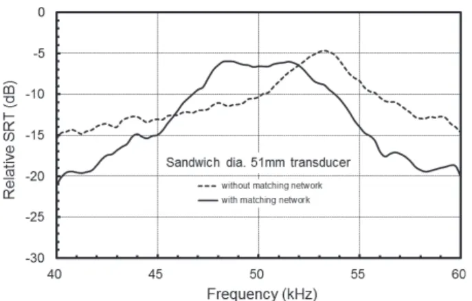
호의송신주파수응답은 51.0 kHz에서가장강하게출현하였 고, -3 dB에대한하한및상한주파수는각각 46.25 kHz, 54.5 kHz이었다. Fig. 3에나타낸수중음향변환기의전기적인 chirp 펄스신호의주파수스펙트럼과 Fig. 5에나타낸음향펄스신호 의스펙트럼을이용하여대역통과정합회로의존재여부에따른 송파감도특성을비교, 분석한결과는 Fig. 6과같다.
Fig. 6에서종축은상대적인송파감도(dB)이고, 횡축은주파
수(kHz)이다. 또한, 점선과실선은각각정합회로가없는경우
와 Bessel 대역통과정합회로가내장된음향변환기에대한송
파감도이다. Fig. 6에서정합회로가없는음향변환기에서는송 파감도의 peak 레벨은 50.5 kHz에서출현하였다. 이주파수
를기준으로측정한 -3 dB에대한하한및상한주파수는각각
48.5 kHz, 52.25 kHz로서, 그대역폭및기계적품질계수는각 각 3.75 kHz와 13.47이었다. 한편, 정합회로를갖는음향변환 기의경우에있어서는송파감도의 peak 레벨은 50.75kHz에서 출현하였다. 이주파수를기준으로측정한 -3 dB에대한하한 및상한주파수는각각 46.25 kHz, 54.5 kHz로서, 그대역폭및 기계적품질계수는각각 8.25 kHz와 6.06이었다. 이들의결과
는 Fig. 5에나타낸음향펄스신호의시간-주파수송신응답특성
과일치하였다. 즉, 대역통과정합회로가있는경우와없는경우
(a)
(b)
(a)
(b)
(a)
(b)
(a)
(b)
Fig. 7. Comparison of the measured (solid line) and calculated transfer functions (dot line) for sandwich type acoustic transducer with a bandpass matching network.
(a)
(b)
(a)
(b)
(a)
(b)
(a)
(b)
Fig. 8. Time-frequency response characteristics of the received chirp pulse signal for sandwich type acoustic transducer without (a) and with a bandpass matching network (b).
대역통과 정합회로를 이용한 수중음향변환기의 대역폭 확장 707
에대한주파수대역폭에는큰차이가있었다. 즉, Bessel 대역 통과정합회로를갖는샌드위치형음향변환기의주파수대역폭 은정합회로를갖지않는경우에비해송파감도의대역폭이약 120% 정도확장되었다.
측정 및 수치 시뮬레이션에 의한 송파감도의 비교
Fig. 2에나타낸대역통과정합회로를내장하고있는샌드위
치형음향변환기의송신모드에대한전달함수의측정및수치 계산패턴을비교, 분석한결과는 Fig. 7과같다. Fig. 7에서실선 은전달함수의측정패턴이고, 점선은 (1)식에의한수치시뮬레 이션패턴이다. 또한, Fig. 7의 (a)와 (b)는각각전달함수의진폭 및위상특성이다. Fig. 7의측정패턴은 Fig. 6의송파감도의패 턴과일치하는패턴으로서 ripple이거의없는완만한음향방사 패턴을나타내었다. 그러나, 수치시뮬레이션에의한주파수응 답패턴에서는측정패턴과달리 3개의 peak 모드가출현하였다. 즉, 가장강한 peak 응답은 50.75 kHz에서출현하였고, 이주파 수를기준으로 46.95 kHz에서 -2.86 dB의제2의 peak 응답과 54.26 kHz에서 -3.83 dB의제3의 peak 응답이출현하였다. 이 와같은수치시뮬레이션패턴은 Fig. 4의 (a)에나타낸입력전 기임피던스패턴에서진폭이최소가되는 3개의공진주파수 와매우밀접한관계를갖고있다. 즉, Fig. 7에서 3개의 peak 응 답은 Fig. 4의 (a)에대한공진주파수가출현하는 46.51 kHz, 50.43 kHz 및 55.39 kHz 부근에서출현하였다. 그러나, 송파모 드에대한전달함수의전반적인응답특성을살펴보면, 수치계 산에서는비록 3개의 peak 응답패턴이출현하였지만, 수중으로 음향에너지가방사되는송신특성에서는거의유사한경향을나 타내고있음을알수있었다.
샌드위치형 음향변환기의 수파감도 특성
실험수조에 2 set의샌드위치형음향변환기를 1.2 m 분리시
켜서로마주보도록설치한후, 한쪽에서는 Fig. 3의전기적인
chirp 신호를수중으로송출하고, 다른쪽에서는음향펄스신호
를수신하여그시간-주파수수신응답특성을구한결과는 Fig.
8과같다.
Fig. 8에서송신용에는대역통과정합회로가내장되어있었지
만, 수신용에는대역통과정합회로를스위치를통해 ON/OFF 할수있도록하였다. Fig. 8에서 (a)는정합회로를 bypass시킨 음향변환기의시간-주파수수신응답특성이고, (b)는 Bessel 대 역통과정합회로를거쳐수신한음향변환기의시간-주파수수 신응답특성이다. Fig. 8 에서시간응답파형과주파수응답스펙 트럼은 Fig. 5와유사한경향을나타내었다. 또한, 이들수신주 파수응답스펙트럼에서진폭은최대값을 0 dB로정규화하여 0-30 dB 범위에대하여나타내었다. Fig. 8의 (a)에서정합회로 를 bypass시킨음향변환기에대한수신 peak 레벨은 53.25 kHz 에서출현하였다. 한편, Fig. 5의 (b)에서정합회로를거쳐수신 한음향변환기의수신 peak 레벨은 50 kHz를전후하여각각 48.5 kHz와 51.5 kHz에서서로대칭적으로출현하였다.
한편, Fig. 5의 (b)에나타낸수중청음기에의해수신한음향 펄스신호의주파수스펙트럼과 Fig. 8의음향펄스신호의스펙 트럼을이용하여대역통과정합회로의존재여부에따른수파 감도특성을비교, 분석한결과는 Fig. 9와같다. Fig. 9에서종 축은상대적인수파감도(dB)이고, 횡축은주파수(kHz)이다. 또 한, 점선과실선은각각정합회로를 bypass시킨경우와 Bessel 대역통과 정합회로를 접속한음향변환기에 대한수파감도이 다. Fig. 8에서정합회로를 bypass시킨경우, 수파감도의 peak 레벨이출현하는 53.25 kHz를기준으로측정한 -3 dB의하한 및상한주파수는각각 51.25 kHz, 54.5 kHz로서, 그주파수대 역폭및기계적품질계수는각각 3.25 kHz, 16.38이었다. 한편, 정합회로를접속한음향변환기의수파감도는 50 kHz를기준으 로서로대칭적인패턴을나타내었다. 따라서, 50 kHz를기준으
(a)
(b)
(a)
(b)
(a)
(b)
(a)
(b)
Fig. 9. Frequency response characteristics of the relative receiving sensitivity (SRT) for sandwich type acoustic transducer without (dot line) and with a bandpass matching network (solid line).
(a)
(b)
(a)
(b)
(a)
(b)
(a)
(b)
Fig. 10. Frequency response characteristics of the relative figure of merit (FOM) for sandwich type acoustic transducer without (dot line) and with a bandpass matching network (solid line).
708 이대재
로 -3 dB의하한및상한주파수를측정하면, 그값은각각 47.0 kHz, 53.75 kHz이었고, 그주파수대역폭및기계적품질계수 는각각 6.75 kHz, 7.41이었다. 이로부터정합회로의존재여부 에따라수파감도의주파수대역폭에도큰차이가있음을알수 있었다. 즉, Bessel 대역통과정합회로를갖는샌드위치형음향 변환기의수신대역폭은정합회로를갖지않는경우에비해수 파감도의대역폭이 100.8% 정도확장되었다.
샌드위치형 음향변환기의 FOM 성능특성의 비교 본연구에서제작한 Fi. 1의 (a)에나타낸음향변환기에 Fig.
2의 Bessel 대역통과정합회로를접속시킨경우에대한 FOM (figure of merit) 성능특성을구한결과는 Fig. 10과같다. Fig.
10에서종축은상대적인 FOM 레벨(dB)이고, 횡축은주파수 (kHz)이다. 또한, 점선과실선은각각정합회로가없는경우와
Bessel 대역통과정합회로가내장된음향변환기에대한 FOM
성능패턴이다. Fig. 10에서정합회로가 없는음향변환기에서 는 FOM의 peak 레벨이 52.75 kHz에서출현하였다. 이주파수
를기준으로측정한 -3 dB에대한하한및상한주파수는각각
49.5 kHz, 53.75 kHz로서, 그대역폭및기계적품질계수는각 각 4.25 kHz와 12.41이었다. 한편, 정합회로를갖는음향변환
기의 FOM 성능특성은 50 kHz를기준으로서로대칭적인패
턴을나타내었다. 따라서, 50 kHz를기준으로 -3 dB의하한및 상한주파수를측정하였는데, 이들주파수는각각 46.25 kHz, 54.5 kHz이었다. 즉, FOM의주파수대역폭및기계적품질계 수는각각 5.75 kHz, 8.70이었다. 이들의결과로부터정합회로
의존재여부에따라 FOM 성능특성의주파수대역폭에큰차
이가있음을알수있었다. 즉, Bessel 대역통과정합회로를갖 는샌드위치형음향변환기의 FOM 성능특성에대한주파수대 역폭은정합회로를갖지않는경우에비해약 35% 정도확장 되었다.
이들의결과로부터우리나라어선에서가장많이사용하고있
는 50 kHz용어군탐지기의샌드위치형음향변환기에본연구
에서제시한 Bessel 대역통과정합회로를내장시키면주파수
대역폭이증대되어어족생물의식별분해능을더욱향상시킬 수있을것으로판단된다.
사 사
이논문은부경대학교자율창의학술연구비(2019년)에 의하 여연구되었음.
References
Airmar Technology Corporation. 1994. Airmar product catalog.
NH, U.S.A., 14-15.
Bowick C. 1982. RF circuit design. Elsevier Inc., Englewood Cliffs, NJ, U.S.A., 59-64.
Coates R. 1991. The design of transducers and arrays for un-
derwater data transmission. IEEE J Ocean Eng 16, 123-135.
Coates R and Maguire PT. 1989. Multiple-mode acoustic trans- ducer calculations. IEEE Trans Ultrason Ferroelect Freq Contr 36, 471-473.
Coates R and Mathams RF. 1988. Design of matching networks for acoustic transducers. Ultrasonics 26, 59-64.
Dong Y and Cui Y. 2012. Analysis of a new joint time-frequency distribution of suppressing cross-term. Res J Appl Sci Eng Technol 4, 1580-1584.
Hong JS and Lancaster MJ. 2001. Microstrip Filters for RF/Mi- crowave Applications. John Wiley & Sons, Inc., New York, NY, U.S.A., 48-56.
Lee DJ. 2014. Bandwidth enhancement of a broadband ultrason- ic mosaic transducer using 48 tonpilz transducer elements with 12 resonance frequencies. Korean J Fish Aquat Sci 47, 302-312. http://dx.doi.org/10.5657/KFAS.2014.0302.
Lee DJ. 2015. Time-frequency analysis of broadband acoustic scattering from chub mackerel Scomber japonicas, goldeye rockfish Sebestes thompsoni, and fat greenling Hexagram- mos otakii. Korean J Fish Aquat Sci 48, 221-232. http://
dx.doi.org/10.5657/KFAS.2015.0221.
Lee DJ. 2017. Bandwidth improvement of a multi-resonant broadband acoustic transducer. Korean J Fish Aquat Sci 50, 605-615. http://dx.doi.org/10.5657/KFAS.2017.0605.
Lee DJ, Kwak MS and Kang HY. 2014. Design and develop- ment of a broadband ultrasonic transducer operating over the frequency range of 40 to 75 kHz. Korean J Fish Aquat Sci 47, 292-301. http://dx.doi.org/10.5657/KFAS.2014.0292.
Lee DJ, Kang HY and Pak YY. 2016. Time-frequency feature extraction of broadband echo signals from individual live fish for species identification. Korean J Fish Aquat Sci 49, 214-223. http://dx.doi.org/10.5657/KFAS.2016.0214.
Murata MFG. 1978. Ceramic ultrasonic transducer catalog (P311/78). Kyoto, Japan, 1-4.
Radmanovic M and Mancic D. 2004. Design and modeling of the power ultrasonic transducers. MP Interconsulting, Le Locle, Switzerland, 131-135.
Stansfield D. 1991. Underwater electroacoustic transducers.
Bath University Press, Bath, U.K., 119-141.
Tokin. 1999. Piezoelectric ceramics Catalog (VR-07JE). Tokyo, Japan, 1-35.
Winder S. 2002. Analog and digital filter design. Elsevier Inc., Englewood Cliffs, NJ, U.S.A., 49-52.