DOI: http://dx.doi.org/10.14579/MEMBRANE_JOURNAL.2015.25.4.367
수학적 귀납법을 이용한 정삼투 및 압력지연삼투 공정의 투과율 불균형 해석
Albert S. Kim
†⋅이 승 원*하와이대학교 토목환경공학과, *선박해양플랜트연구소 (2015년 7월 14일 접수, 2015년 8월 31일 수정, 2015년 8월 31일 채택)
Intrinsic Flux Inequality in Forward Osmosis (FO) and Pressure-Retarded Osmosis (PRO) Processes
Albert S. Kim
†and Seung-won Lee*
Department of Civil and Environmental Engineering, University of Hawaii at Manoa, 2540 Dole Street, Honolulu, Hawaii 96822, United States
*Seawater Utilization Plant Research Center, Korea Research Institute of Ships & Ocean Engineering, Goseong-gun, Gangwon-do 24747, Republic of Korea
(Received July 14, 2015, Revised August 31, 2015, Accepted August 31, 2015)
요 약: 정삼투와 압력지연삼투 공정에서 용매의 투과율은 용매와 막이 접촉하는 방식에 의존한다. 각각의 공정에서 막의 활성층이 고농도 용매와 접촉하는 경우를 압력지연삼투 방식이라 하고, 고농도 용매가 막의 다공성 지지하층과 직면해 있는 경우를 정삼투 방식이라고 한다. 압력지연삼투 방식과 정삼투 방식은 각각 희석형 그리고 농축형의 내부농도 분극 현상을 유 발하는데, 동일한 조작 조건에서 정삼투 방식보다 압력지연삼투 방식이 높은 투과율을 나타내는 현상이 실험적으로 관측되었 다. 본고에서는 정삼투방식과 압력지연삼투 방식에서 발생하는 본질적인 투과율 불균형을 수학적 귀류법을 이용하여 증명하 고, 물리적인 원인을 규명한다.
Abstract: In pressure-retarded osmosis (PRO) and forward osmosis (FO) processes, solvent (permeate) flux depends on which surface the draw solution faces. There are two operation modes. PRO mode indicates that the active layer faces the draw solution, and FO mode means that the porous substrate fronts the draw stream. It is often observed that the PRO mode produces higher flux than that of FO under the same operating conditions. The current work uses the method of proof by contradiction, and mathematically proves the intrinsic flux inequality between the two modes.
Keywords: Forward osmosis, Pressure-retarded osmosis, Internal concentration polarization, Flux inequality, proof by contradiction
1. Introduction 1)
Seawater desalination and water recycling are two primary methods to resolve significant water scarcity in the 21st century[1]. Depending on availability of energy resources in specific regions, thermal or membrane process can be used for desalination. Reverse osmosis (RO) is a pressure-driven membrane filtration process,
which requires a substantial amount of electric energy to provide hydraulic pressure. This pressure is higher than the osmotic pressure of seawater and applied to feed side of the membrane surface. Instead, pressure-re- tarded osmosis (PRO) utilizes the chemical potential difference between fresh and saline water to generate net hydraulic pressure proportional to their osmotic pressure difference. This pressure can be used to rotate
†
Corresponding author(e-mail: [email protected], http://orcid.org/0000-0002-9027-4616)
a turbine for power generation. Commercialization of PRO still requires further development of highly per- meable membranes and efficient system design including real-time energy recovery. Forward osmosis (FO) uses the same thermodynamic principle to extract the solvent (water) from the saline stream to the draw stream.
Specific draw solutes should be prepared prior to FO commercialization, which are non-toxic, easily re- movable, and of high osmotic pressure. Osmosis-driven PRO and FO technologies have descent potential for re- newable desalination using significantly less energy than RO. Fundamental principles, current stage, and fu- ture perspectives of PRO and FO can be found else- where[2-4].
Since RO is pressure-driven, the permeate flux direc- tion is pre-determined as oriented from the feed side (on the active layer) to the permeate side. The intermediate substrate supports the thin active layer and does not sig- nificantly influence the filtration performance. Unlike RO, the driving force of PRO is the Gibbs free energy difference of solution between fresh water (~0 ppm) and seawater (35,000 ppm). FO also uses the spontaneous solvent transport from seawater to draw solution caused by the transmembrane concentration difference.
The draw concentration is often a multiple of seawater concentrations. Having the renewable driving force of the concentration gradient, PRO and FO have a free- dom to change the direction of the solvent flux, either from the active layer side to the supporting substrate side or vice versa. The solute flux direction is always opposite to the solvent flux direction. The former is called PRO mode and the later FO mode. It was ques- tionable that, given same operating conditions, one of PRO and FO modes has universally high flux than the other.
2. Background
Elemelech and McCutcheon compared solvent fluxes of PRO and FO modes by exchanging draw and saline concentrations on the active layer[5]. In their experi-
ments, the saline concentration varies from 0.05 to 1.0 M with an interval of 0.05 M, and the draw concen- tration is fixed as 1.5 M. As the saline concentration decreases, the PRO-mode flux increases from 1.14 to 8.82 µm/s, and the FO-mode flux increases from 1.06 to 5.05 µm/s. At each draw-saline concentration pair, PRO-mode flux is generally higher than the FO-mode flux. (See Table 1 of Ref.[5] for details.) Gray et al.[6]
compared the performance of PRO and FO modes with a fixed draw concentration of 0.5 M. As the saline con- centration decreases from 0.375 to 0.0625 M NaCl, PRO-mode flux increases from 0.051 to 0.302 m/day, and FO-mode flux increases from 0.055 to 0.185 m/day.
At the highest saline concentration, FO-mode flux slightly exceeds the PRO-mode flux. This must be be- cause the concentration difference between the saline and draw solutions is small and so the flux difference is within an experimental uncertainty. In all other pairs of draw-saline solutions, PRO-mode flux is higher than FO-mode flux. (See Table 1 of Ref.[6] for details.) In this work, we mathematically prove that PRO-mode flux is unconditionally higher than FO-mode flux if operat- ing conditions and parameters are identical.
3. Mass Transfer
In this section, we briefly review fundamental trans- port mechanism of RO, PRO, and FO processes in terms of mass transfer, driving force, and flux direction.
3.1. Reverse Osmosis (RO)
Transport phenomena are often explained using sol- ution-diffusion model in RO process[7]. The solvent flux of RO is expressed as
∆
∆∏ (1)where A is the solvent permeability, ∆P is the ap- plied pressure, and ∆∏ is the osmotic pressure differ- ence across the membrane. The solute flux across the
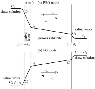
Fig. 1. A schematic representation of concentration polar- ization across a skinned membrane in (a) PRO and (b) FO modes. In both modes, draw solution is used to draw sol- vent from the saline water. The direction of the solvent flux J
wis to the left in PRO mode and that of Jʹ
wis to the right in FO mode. The draw concentration in both modes are set to be equal : = C
1= Cʹ
1.
RO membrane is :
∆
(2)where B is the solute (salt) permeability and ∆C is the solute concentration difference across the membrane.
When the (external) concentration polarization is insig- nificant, ∆C and ∆∏ can be approximated as their differences between the feed and permeate streams, i.e.,
∆∏ ≅ ∏ ∏ and ∆
≅
, where subscript ‘f’and ‘p’ indicate feed and permeate, respectively. The solvent permeability A is often measured using fresh water as feed solution. Because the osmotic pressure of fresh water is zero, ∆∏ term in Eq. (1) disappears.
Then, the slope of Jw versus ∆P provides solvent per- meability A. Using Eq. (2), the solute permeability B can be calculated as
.3.2. Forward osmosis
Two fundamental PRO theories by Lee et al.[8] and Loeb et al.[9] are often used to analyze experimental
data obtained in PRO and FO modes, respectively. Fig.
1 shows directions of solvent and solute fluxes and solute concentration profiles across the membrane con- sisting of the active layer and the porous substrate. For PRO power generation, draw solution and saline water can be replaced by seawater and fresh water, respectively. For FO desalination, saline water is sea- water, and draw solution should be a specific solution having (much) higher osmotic pressure than that of seawater. As indicated above, PRO and FO modes shown in Fig. 1 were originally developed for PRO, and later used (more) actively for FO processes. In RO, solutes are carried by the solvent flow within the porous substrate after they diffuse through the active layer. In PRO and FO, the net solute flux within the substrate is counter-balanced by the solvent flux in the opposite direction. Even if the same membrane is used for RO and PRO/FO processes, the heterogeneity of the driving forces may cause the effective A and B different. We assume, however, that these permeability values are invariant with respect to experimental con- ditions and operating modes. Here, we briefly review Lee et al.[8]’s and Loeb et al.[9]’s theoretical ap- proaches as follows.
Summary of Lee et al.’s work[8] : Mass balance in PRO mode
The water flux across the active layer ( < x < 0) may be represented as
(3)where C2 and C3 are concentrations at the interface between the draw stream and active layer ( ) and that between the active layer and porous substrate ( ), respectively, and ∏ and ∏ are osmotic pres- sures at the corresponding concentrations. In Eq. (3), the osmotic pressure can be expressed as ∏
for solute concentration Ci (for i = 1-5). Here, Rgis the
universal gas constant, T is the absolute temperature, k is the dissolution coefficient (which is 2 for NaCl aftercomplete dissolution), and
is the phenom- enological proportionality between the solvent flux and the concentration difference. Geometrical and physical characteristics of the porous layer are represented using a single parameter[8] :
where δs is thickness, ε is porosity, τ is diffusive tortuosity of the porous substrate, and D is the solute diffusivity in the bulk phase. Lee et al.[8] interpreted
K as “a measure of resistance to salt transport in the
porous substrate”, which is derived as
ln
∏
∏
(5)
For a specific membrane of A and B, K can be cal- culated using measured solvent flux Jw. ∏ and ∏ are often approximated as those of (bulk) draw and saline solutions, i.e., ∏≅ ∏ and ∏≅ ∏. These approx- imations are valid for fast channel flow causing insig- nificant external concentration polarization. Derivation of Eq. (5) uses the solute flux represented as
(6)Dependences of Jw (of Eq. (3)) and Js (of Eq. (6)) on C2-C3 stem from the thinness of ≪ , which fundamentally implies the linearity of solute concen- tration across the thin active layer. A static mass bal- ance within the porous substrate is
for 0 < x < δs (7)where
is the effective solute diffusivity within the tortuous interstitial spaces in the porous substrate. The interfacial concentration C3 between the active layer and the porous substrate is represented in terms of C2 and C4 :
(8)
When the external concentration polarization is insig- nificant, C3 of Eq. (8) can be calculated using meas- ured Jw and estimated K of Eq. (5), where
≅
and
≅
are used.Summary of Loeb et al.’s work[9] : Mass balance in FO mode
The solvent and solute fluxes in FO mode may be expressed as
ʹ
∏ʹ ∏ʹ (9) and
ʹ
ʹ
ʹ (10)respectively. For simplicity, we use prime (ʹ) symbol to specify quantities of FO mode, and unprimed varia- bles either for PRO mode or for both. The mass trans- fer resistance of the porous layer is alternatively repre- sented as
ʹ
ʹ ln
∏ʹ
ʹ
∏ʹ(11)
which must be equal to K of Eq. (5) unless A or B changes with operation modes. The concentration at the membrane-substrate interface is calculated as
ʹ
ʹ
ʹ
ʹ
ʹ ʹ
ʹ ʹ(12)
of which functional form resembles that of Eq. (8).
Similar to C3, estimation of Cʹ3 requires measured or known information of Jʹw,
ʹ≅
ʹ, and
ʹ≅
ʹ.4. Theoretical
Why does PRO mode provide higher flux?
It is often experimentally confirmed that the solvent flux in PRO mode is generally higher than that of FO mode[4,5], which must be due to a higher degree in ICP of FO mode. However, to the best of our knowl- edge, this flux inequality has not been fundamentally addressed or mathematically proven. Here we use the method of the proof by contradiction to logically de- rive the flux inequality as follows :
1. We accept the experimental observations of Jw > Jʹw
[4,5] as logically true, and assume that theoretical rep- resentations of Jw and Jʹw (of Eqs. (5) and (11), re- spectively) are correct.
2. We make a false assumption that the FO-mode flux is higher than the PRO-mode flux, i.e., Jw < Jʹw, which is equivalent to
ʹ (13)
We substitute Eqs. (5) and (11) into (13) to write
∏
∏
∏ʹ
ʹ
∏ʹ(14)
and re-organize Eq. (14) as
ʹ
∏
∏ʹ ∏ ∏ ∏ʹ ∏ʹ (15)
Here, we assume that
∏ʹ
∏
∏
∏ʹ is close to zero or negligible as compared to
∏ʹ
, and then rewrite Eq. (15) as
ʹ
∏
∏ʹ(16)
after replacing Jw in the denominator of Eq. (15) by
∏
∏.3. Because ∏ is higher than ∏, if ∏≅ ∏ʹ, then
∏≅ ∏ʹ. This makes the right hand side of Eq. (16) less than 1 and indicates Jw > Jʹw, which is contra- dictory to the initial assumption. Here, we conclude that Jw > Jʹw is true by proving that Jw < Jʹw is in- trinsically false. Note that the only condition used is the insignificant external concentration polarization due to fast channel streams.
In addition, Jʹw can be close enough to Jw if C3 con- verges to Cʹ4 (approximated as C4). Eq. (8) indicates that this is possible only if the supporting layer is ab- sent, and therefore the mass transfer resistance from the supporting layer vanishes, i.e., mathematically K → 0.
This ideal condition can fully remove the ICP and let
Jʹ
wreach J
w, but this is practically impossible. The flux inequality is, therefore, fundamentally unavoidable in FO and PRO processes.5. Conclusions
It was experimentally observed that the performance of PRO/FO is higher if the draw solution faces the ac- tive layer in literature. This is because the internal con- centration polarization in the porous substrate is more significant if the draw solution fronts the porous substrate. Assuming that Lee et al.’s[8] and Loeb et al.’s[9] theories fully explain the osmosis-driven phe- nomena, we theoretically compare the permeate fluxes of the PRO and FO modes. The proof by contradiction was used to address the flux inequality between the two operation modes. We prove that, given same operating conditions, the PRO-mode provides unconditionally higher flux than that of the FO-mode. The primary rea- son is that the solute and solvent fluxes are counter-bal- anced in opposite directions across the membrane. The FO-mode flux can reach the PRO-mode flux only if the substrate does not exist (or extremely thin), which is practically challenging. We finally conclude that the flux inequality is intrinsically unavoidable.
Acknowledgments
This work was financially supported by the National R&D project of “Development of new application tech- nology for deep seawater industry” funded by the Ministry of Oceans and Fisheries of the Republic of Korea.
Reference
1. I. C. Escobar and A. Schäfer, “Sustainable Water for the Future: Water Recycling versus Desalination”, Elsevier, Amsterdam, The Netherland (2010).
2. T. Y. Cath, A. E. Childress, and M. Elimelech,
“Forward osmosis: Principles, applications, and re- cent developments”, J. Membr. Sci., 281(1-2), 70 (2006).
3. D. L. Shaffer, J. R.Werber, H. Jaramillo, S. Lin, and M. Elimelech, “Forward osmosis: Where are we now?”, Desalination, 356, 271 (2015).
4. A. Deshmukh, N. Y. Yip, S. Lin, and M. Elimelech,
“Desalination by forward osmosis: Identifying per- formance limiting parameters through module-scale modeling”, J. Membr. Sci., 491, 159 (2015).
5. M. Elimelech and J. R. McCutcheon, “Influence of concentrative and dilutive internal concentration polarization on flux behavior in forward osmosis”,
J. Membr. Sci., 284(1-2), 237 (2006).
6. G. T. Gray, M. Elimelech, and J. R. McCutcheon,
“Internal concentration polarization in forward os- mosis: role of membrane orientation”, Desalination,
197(1-3), 1 (2006).
7. M. Mulder, “Basic Principles of Membrane Technology”, Kluwer, Dordrecht, TheNetherlands (1996).
8. K. Lee, R. Baker, and H Lonsdale, “Membranes for power generation by pressure-retarded osmo- sis”, J. Membr. Sci., 8(2), 141 (1981).
9. S. Loeb, L. Titelman, E. Korngold, and J.
Freiman, “Effect of porous support fabric on os- mosis through a Loeb-Sourirajan type asymmetric membrane”, J. Membr. Sci., 129(2), 243 (1997).