실시간 선박관리 시스템
Lim Chia Syan*․박수홍**
Real-Time Marine Vehicle Management System
Lim Chia Syan*․Soo-Hong Park**
요 약
본 연구는 선박과 주위상태를 기지국에서 실시간으로 모니터링하고 기록하는 선박 관리 시스템에 대한 연 구이다. 독점적인 시스템 메세지가 통신에 중개되도록 설계되어 있다. 디바이스 표준에 의하여 특정시스템 메 시지가 규격화되고, 시스템에 부착되어진 각 통신장치에 특정화되도록 설계하였다. 또한 새로운 구성으로 관 리자에 의해 원격으로 결정될 수 있는 기지국에 메시지를 선박상태를 업데이트하는 방법을 결정하도록 설계 하였다
ABSTRACT
In this paper, an effort has been made to design a Real-time Ship Management System where the status of a ship and its surrounding are constantly monitored and recorded at the base station. Proprietary system message based on overhead and checksum encapsulation has been designed to facilitate the communication. Software encoder and decoder are developed independently for each communication device attached to the system to process the proprietary system message into format by device standard. In addition, few configurations are designed to determine the method of updating the ship status message to the base station, which could be remotely chosen by the administrator.
키워드
Ship Management, Real Time Monitering, Communication Device, Base Station 선박관리, 실시간모니터링, 통신디바이스, 기지국
* 동서대학교 대학원 메카트로닉스공학과
** 교신저자(corresponding author) : 동서대학교 메카트로닉스공학과 ([email protected])
접수일자 : 2013. 04. 21 심사(수정)일자 : 2013. 06. 20 게재확정일자 : 2013. 07. 23
Ⅰ. INTRODUCTION
A Real-time Ship Management System serves the purposes of data acquisition, data analysis and data communication with the base station, carried out on a marine vehicle. Information retrieved from the system is stored in database and intended for future analysis and presentation. The Real-time
Ship Management System comprises two sub- systems, namely the base station gateway and the embedded system installed on the ship.[7]
In this paper, the system configuration of both base station and ship embedded system are illustrated and described. Then, the status update modes available for selection based on preference by the administrator are explained in details.
Besides, the system proprietary messages en- forced for communication are presented in the following section. Finally, the results exhibiting the delay between transmitting the control command message and upon receiving the confirmation acknowledgement are located in the next section.[8,9,10]
Ⅱ. SYSTEM DESCRIPTION
A Real-time Ship Management System is a 16-bit data acquisition system used to obtain data from sensors installed on the ship, performing operations to extract valuable information from the data and transmit back to the base station via attached communication devices. The system could be described and explained based on three major features.[1,2]
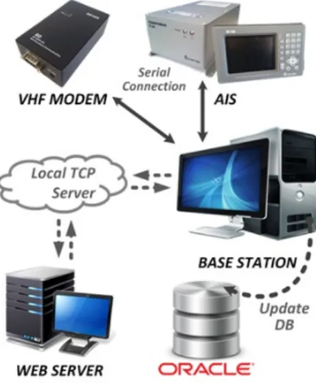
Fig. 1 Base station system configuration
Data and signals are captured utilizing various peripheral interfaces such as analog, digital and serial interface from various sensors or devices.
This information indicates the status of the ship and its surrounding which is monitored at the base station wirelessly. Specific operation is required to
process the incoming data and signals in order to extract information from within which is unde- rstandable by human. Besides, data from device such as AIS must be decoded specifically prior to any data processing. Useful information obtained and intended for base station must be encoded specifically for each available and online com- munication device before ready for transmission.
A. System Configuration
Referring to Fig.1, the base station serves the purpose of presenting the status of the ships to the administrator and store incoming information into database. Communication devices such as AIS and VHF and TCP server are connected manually by the administrator upon startup of the system. However, database connection is only established when data is completely decoded, organized and ready for storage.
Besides, the identity of the base station must be first confirmed by the administrator via the MMSI information encapsulated in AIS message, enabling further communication to take place. [3, 4]
Referring to the block diagram in Fig. 2, it is noticed that the system configuration is relatively simple for understanding. Communication devices such as AIS, CDMA modem and VHF modem which are connected to the system using serial interfaces (UART). In addition, analog-to digital (ADC) peripheral is used to monitor the voltage from the battery through a voltage divider circuit and directly from the temperature sensors.
Fig. 2 Hardware and sensors interfacing
Fig. 3 Basic sensor interface with opto-isolator
Next, digital devices such as passive infrared sensor and magnetic door sensor is connected to the digital input through an opto-isolator res- pectively as the pre-cautious for any voltage surge from the sensors. Lastly, the system also functions as a wireless remote control for alarm and light on the ship utilizing its digital output capability of the system through relay connection When the sensor is installed for short distance, it can be attached directly to the optocoupler based on the basic configuration illustration as shown in Fig. 3.
However, when the sensor is installed far from the embedded system, there is a significant amount of resistance in the wire which could greatly reduce the current supplied to the optocoupler causing logic error to the system. Therefore, an additional BJT is used to solve the problem because the base of the BJT requires a small amount of current to turn on the switch which could be adapted to long wiring sensor as shown in Fig. 4.
Fig. 4 Long wiring sensor interface with opto-isolator
B. Firmware Update and Configuration
In NMEA-0183 standard, protocol overhead should have similar pattern across different products which is a great advantage when designing a generalized
encoder or decoder. The parameters for each device may be differ from another but the process sequence of encoding and decoding could be implemented if sufficient information is provided to the parameter and the rule list when a new device is added to the system. Besides, parameter and rule should be entered by the user using the template that has been provided, which is recognized by the system as illustrated in Fig. 5.
Utilizing this standard, development time could be greatly reduced and minimize the error since one generalize standard is used.
Fig. 5 User configuration on parameter and rule list
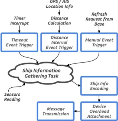
C. Ship Information Gathering Overall Process Referring to Fig. 6, the ship information task is responsible for collecting all the necessary ship information required by the application before being transmitted back to the base station.
Fig. 6 Ship information gathering task
D. Ship Management System Operating Mode
1) Timeout-trigger Update
This mode is enabled by default where the ship status message is sent to the base station in a constant time interval, resetting the timeout counter as illustrated in Fig. 7. Therefore, if the message fails to reach base station at the instant of each interval, the embedded system should be inspected for any failure.
Fig. 7 Timeout-trigger event illustration 2) Manual-trigger Update
Fig. 8. Manual-trigger event illustration
When ship status is intended to be viewed instantly by the administrator, command could be sent manually to the ship at the terminal, requesting the status. The next update is only available for requesting when the previous status is successfully obtained in order to minimize communication congestion as shown in Fig. 8.
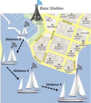
3) Distance-trigger Update
In Fig. 9, the event for ship information gathering is triggered by distance. Shortest distance over earth surface which is also known as the great-circle distance could be computed utilizing haversine formula, given the longitude and latitude
Fig. 9 Distance-trigger event illustration
for the two points. As compared to the spherical law of cosines, haversine formula is favorable for small distance calculation, which yields a more accurate result. Trigonometry functions in haversine formula only work on angle values in radians.
Haversine formula[2] is
sin∆
coscossin∆
(1)
where R is earth's mean radius of 6,371km
E. Protocol Message Format
In a system dealing with several types of data, checksum and encapsulation are often advisable carried out on the data to ensure data integrity during communication. System proprietary messages have been designed accordingly to the NMEA-0183
standard which includes overhead and checksum, encapsulating the data. Therefore, software enc- oding and decoding are required upon transmission and reception respectively, imposing complexity to the system. [5, 6]
Device overhead must be attached to the message intended to be transmitted utilizing the format which is recognized by the device respectively. The device overhead appended to the message acting as a command, assisting the device to identify the message type. Therefore, the final transmitted message could be encoded into different format by the device. However in some cases, for example VHF modem does not required device overhead for normal operation. The final message is relayed from the serial interface and transmitted in the device physical layer without any alternation.
However, overhead is introduced in the system to distinguish the message type amongst nodes installed with the device. Encoding is required in order to encapsulate the information in different size which could be comprehended by the communication device.
Ship status message is designed to report the status of the ship back to the base station. Data is displayed at the terminal in graphical form and inserted into database for future reference.
Devices attached to the system digital output ports could be controlled remotely via the base station terminal. The state of the devices is updated at the terminal for every ship status message received and could be toggled by user.
Any change in state must be confirmed manually by the user before the control message is transmitted to the ship in order to avoid any communication congestion. However, the state on the display is only refreshed when the acknowledgement message is received at the base station.
Usage of VHF modem is straightforward where data is transmitted directly without any encoding at
the modem. Beacon message is broadcasted and intended to notify other ships that the VHF modem of this ship is available for communication. Thus, the data format is designed to be short and simple, only includes the message type and source MMSI.
F. Message Parsing, Partitioning and Decoding
1) Parsing
When dealing with NMEA-0183 standard, message is always encapsulated with standard overhead pattern before being delivered to another connected endpoint following the exactly identical standard in order to decode and extract the information from the message. Thus, when message is arriving at the designated endpoint, it must be first being parsed to determine the starting and the end of the message, based on the leading and terminating symbols provided by the user.
2) Partitioning
If the message has been successfully being parsed and stored temporarily in the memory, it will be then being partitioned where the long message is split into several fragment using the delimiter symbol provided. Partitioning process ensures the message is broken into smaller pieces, where decoder could be constructed in a relatively easier way by manipulating only the desired parts of the message. Besides, unwanted parts of the message could be ignored and discarded by the end of the decoding process.
3) Decoding
In order to extract information from the message received at the endpoint, a decoder must be provided at the end of the partitioning process.
When entering decoding process, the data part of the message is retrieved from the memory and the decoder could be designed in such a way that only
crucial part of the data is decoded to reduce unnecessary process loading, as well as simplifying the overall decoder design.
Ⅲ. RESULTS AND DISCUSSION
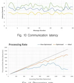
While the reliability and efficiency of data communication are very important factors in the ship management system, the time required for a message to travel from source to destination node is constantly observed to ensure it falls within an acceptable range, without causing data congestion to the processing unit. Since each mechanism operates at different cost, available communication device is selected by the processing unit based on priority in order to minimize the overall operation cost. The communication latency is captured and recorded based on 30 messages of size at 80 bytes.[5,6]
Based Fig. 10, it is noticeable that AIS transponder has the highest communication latency, followed by VHF modem and CDMA modem. The uncertain latency displayed by AIS transponder is due to the time slot and traffic imposed to the standard protocol, whereby messages are constantly transmitted and received and therefore the messages propagation delay could be difficult to predict.
VHF modem on the other hand, has relatively lower communication latency compared to AIS transponder since it is only utilized for user message communication and there is very little traffic when the device is not in used. Beaconing message in software implementation is required to broadcast the device status to nearby VHF modem nodes. Even though VHF modem has lower latency, it also has a very unpredictable behavior which would be caused by the lower transmission power of the device, frequently influenced by the surrounding obstacles. Moreover, VHF modem has
lower baud, limiting the message size of each transfer.
Lastly, CDMA modem has the lowest communication latency amongst but it is the most expensive communication medium where the cost is counted on data size basis and therefore it has the lowest priority. The message is encapsulated and transmitted in GSM/WCDMA frequency where transmission is highly reliable and efficient, allo- wing long range communication.
Fig. 10 Communication latency
Fig. 11 Processing rate
When data reaches the communication devices and received by the system, it should be instantly processed to prevent further accumulation of unprocessed data. Therefore, it is crucial to filter and buffer the incoming data, permitting the processing unit to handle only the data which is vital to the system without going through every bytes.
Referring to Fig. 11, the non-optimized imp- lementation is where the data is received and processed instantly without buffering while opti-
mized implementation includes the parsing, parti- tioning and decoding sub-modules. It is noticeable that there is no difficulty for optimized version to handle high incoming data rate and slightly deteriorate when data rate exceed 1000 bytes/sec.
The non-optimized version on the other hand could not efficiently handle data rate exceeding 500 bytes/sec and continue to deteriorate. The primary factor of this phenomena is caused by the high interrupt routine servicing rate as the incoming data rate increase.
Ⅳ. CONCLUSIONS
Communication reliability and efficiency are the primary considerations when developing the Ship Management System, affecting the whole system performance. Occasionally, software optimization could be employed to improve the performance while minimizing the cost of replacing the communication hardware. In addition, the system also uses proprietary protocol message format for communication, extending the features introduced to the system.
The system could be divided into two subsystems, consisting of the PC-based base station gateway and embedded system installed on the marine vehicles. Often, the PC-based software is capable of handling mass variety of information at the required speed, easing the optimization process. Embedded system on the other hand, software optimization could be tedious sometimes due to the limitation from the hardware spec- ifications. Real-Time Operating System (RTOS) could be implemented to effectively utilize the resource through time-sharing process, eliminating time wasted in conventional sequential program framework.
감사의 글
“This Research was supported by Dongseo Universty Annual Special Research Grants 2013”
REFERENCES
[1] Microchip dsPIC33EP Reference Manual [Online]. Available : http://www.microchip.co m/ wwwproducts/Devices.aspxdDocName=en5 54307
[2] Distance Calculation Using Longitude and Latitude [Online]. Available : http://www.mo vable-type.co.uk/scripts/latlong.html
[3] TCP Asynchronous Socket Communication [Online]. Available : http://www.codeproject.c om/Articles/1608/Asynchronous-socket-commu nication
[4] Oracle Database Client Data Access in Available : http://www.oracle.com/technetwor k/articles/dotnet/vs2010-oracle-dev-410461.html [5] AIS AIVDM/AIVDO Protocol Decoding
[Online]. Available : http://gpsd.berlios.de/A IVDM.html
[6] AIS Reference Manual for Encoding and Decoding [Online]. Available : http://meeting.
helcom.fi/c/ document_library/get_file?folderI d=75444&name=DLFE-30368.pdf
[7] Soohong Park, Lim Chia San, “Real-Time Ship Management System”, The Korea Institute of Electronic Communication Sciences, Autumn Conference, pp. 223-226, 2012.
[8] Yeon-Jae Oh, Oh-Hoon Cho,.Eung-Kon Kim, Design of 3D Ship Display System using Android”, The Journal of The Korea Institute of Electronic Communication Sciences, Vol. 7, No. 5, pp. 1011-1016, 2012.
[9] Jang-Sik Park, "Ship Detection Using Visual Saliency Map and Mean Shift Algorithm”, The Journal of The Korea Institute of Electronic Communication Sciences, Vol. 8, No. 2, pp.
213-218, 2013.
[10] Seung-jae Oh," ICU Real-Time Sign Info- rmation Transmission System using TMO in Distributed Network Systems”, The Journal of The Korea Institute of Electronic Commu-
nication Sciences, Vol. 4, No. 3, pp. 230-235, 2009.
저자 소개
임치산(Lim Chia Syan)
2011년 7월 말레지아 MultiMedia University 졸업(공학사)
2013년 8월 동서대학교 대학원 메 카트로닉스공학과 졸업예정
※ 관심분야 : 마이트로프로세서응용
박수홍(Soo-Hong Park)
1986년 2월 부산대학교 정밀기계 공학과 졸업 (공학사)
1989년 2월 부산대학교 대학원 기 계공학과 졸업(공학석사)
1993년 2월 부산대학교 기계공학과 졸업(공학박사) 동서대학교 메카트로닉스공학과 교수
※ 관심분야 : 제어 자동화, 로봇공학