IEEE 1588 시간 동기화 성능에 대한 조사
자흐자 리코 하토노
*
․전성용*
․신석주**
A Survey of IEEE 1588 Time Synchronization Performance
Rico Hartono Jahja
*․Seong-Yong Jeon
*․Seok-Joo Shin
**요 약
시간 동기화 프로토콜은 통신의 성능을 결정할 수 있는 중대한 요인 중 하나이며, 최근 네트워크의 빠른 발 전으로 인하여 더욱 탄탄한 시간 동기화 알고리즘이 요구되고 있다. IEEE 1588은 탄탄한 시간 동기화 알고리 즘을 위한 가능한 방법 중 하나이지만, 아직 PDV 값의 감소 및 안정화를 위한 고려되어야 할 몇 가지 문제점 이 남아있다. 본 논문에서는 PTP 메시지 전송의 수정, PTP 메소드 최적화, 필터링 기술, 응용계층의 타임스템 프를 대신하는 H/W 타임스템프 활용 등 IEEE 1588의 성능을 개선할 몇 가지 방법을 조사하여 각 기법의 특 징을 분석하였다. 본 논문에서 소개된 성능의 개선에도 불구하고 네트워크 통신에서 시간 동기화 알고리즘은 아직 개선해야 할 많은 문제점을 가지고 있다.
ABSTRACT
Clock or time synchronization protocol is one of the crucial factors that could determine the quality of the communication. With the rapid development of the network technology, more robust clock synchronization algorithm is required. IEEE 1588 is one of the possible solutions for a robust clock synchronization algorithm; however, there are still some challenges that need to be concerned in IEEE 1588 in term of reducing and stabilizing the PDV value. This survey paper shows several solutions that could improve the performance of IEEE 1588, including modifying the PTP message transmission, optimizing PTP method, filtering techniques, and using the hardware timestamp instead of application layer timestamp, and so on. Despite the improvement that is created with these techniques, the clock synchronization algorithm is still an open issue in the network communication.
키워드
Time Synchronization, PTP Message, PTP Method, TImestamp 시간 동기화, PTP메시지, PTP메소드, 타임스탬프
* 조선대학교 컴퓨터공학과([email protected])
** 교신저자(corresponding author) : 조선대학교 교수([email protected])
접수일자 : 2014. 11. 05 심사(수정)일자 : 2015. 01. 16 게재확정일자 : 2015. 02. 09
Ⅰ. Introduction
Time synchronization is one of the most essential parameters that could determine the qua- lity of the communication. In order to fulfill the
requirements of time synchronization, several solu- tions have been developed, including the most popular one, which is called as IEEE 1588[1], [2].
IEEE 1588 or Precision Time Protocol(PTP) is a
protocol that employs master/slave hierarchy on the
application layer, where a slave synchronizes its clock to the master clock. Theoretically, this IEEE 1588 could achieve very precise clock synch- ronization accuracy, which is sub-microsecond clock accuracy in phase different.
There are a lot of challenges must be faced in order to achieve the synchronization target. For some challenges, IEEE 1588 alone cannot mitigate all the possible factors that can reduce the accuracy of the clock synchronization algorithm.
One of the biggest errors that could be happened in the synchronization process is called as the PDV (Packet Delay Variation)[3]. This PDV is caused by many factors; some of those could be mitigated with using IEEE 1588 while others couldn’t be mitigated with IEEE 1588.
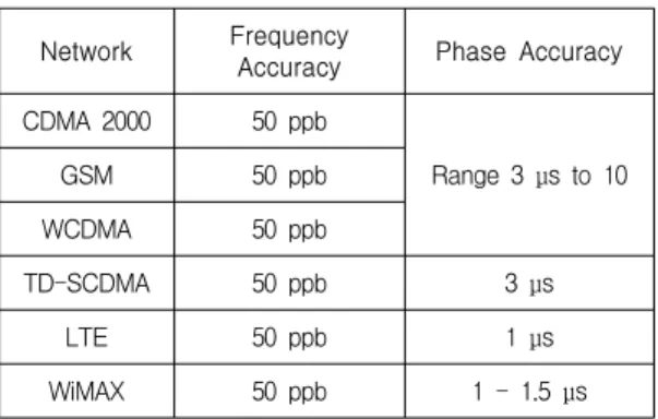
The accuracy requirement of the time synch- ronization could be varies dependent on the network technology itself. table 1 shows time synchronization requirements in many wireless networks in term of the phase accuracy and frequency accuracy[4], [5]. In some research literatures such as [6] and [7] femtocell network synchronization have been discussed. One of the biggest challenges in the femtocell deployment is the synchronization between the femtocells and the macro base stations. 3GPP specifies that a base station should transmit in a very accurate and closely synchronized frequency, which requiring precise clock references. To meet stringent network synchronization requirements, femtocells can use IEEE 1588 for an accurate clock synchronization protocol between networked equipment. By distributing a high precision tie base around the network that is resilient to the typical levels of packet delay and jitter found on broadband Internet connections, a low-cost implementation is possible.
This paper provides overviews about several approaches that involving with IEEE 1588 in order to achieve precise time synchronization in the network.
Network Frequency
Accuracy Phase Accuracy
CDMA 2000 50 ppb
Range 3
μ
s to 10GSM 50 ppb
WCDMA 50 ppb
TD-SCDMA 50 ppb 3
μ
sLTE 50 ppb 1
μ
sWiMAX 50 ppb 1 - 1.5
μ
sTable 1. Synchronization requirements for various systems
Ⅱ. IEEE1588 Standard Protocols
2.1. IEEE 1588
IEEE 1588 or PTP firstly published in 2002. This protocol came as the answer to substitute the earlier clock synchronization protocol, Network Time Protocol(NTP), which couldn’t follow the network clock accuracy requirement at that time.
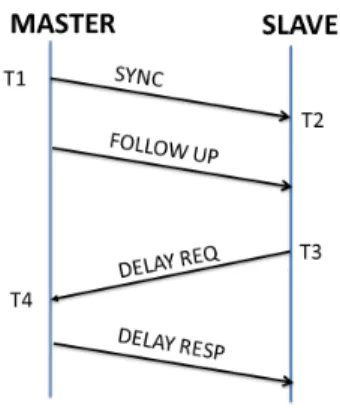
The basic concept of PTP is to perform a synchronization process between master and slave devices with using timestamp messages exchange between them. Fig. 1 shows the default trans- mission of PTP messages. The PTP synchro- nization process starts with the SYNC message, with T1 as the egress timestamp of the message, master node sends it to slave and receive it on T2.
Right after sends SYNC message, master sends
FOLLOW UP message, which contains the physical
layer timestamp of T1. As the SYNC messages
send periodically, so does it with the DELAY REQ,
however, the period of SYNC and DELAY REQ
message could be different. In the meantime, slave
sends DELAY REQ messages periodically to
master node, the egress timestamp of the messages
are called as T3. Subsequently, master receives it
on T4, and right afterwards (after some processing
time delay) master replies with DELAY RESP
message which contains the ingress timestamp of
DELAY REQ message. The highlight of the clock synchronization problem is measuring how much is the time different between master and slave. From fig. 1, in order to be able to measure the time difference between them, there are two values that should be known, which are transmission delay from master to slave, and from slave to master.
The first value should be known from the SYNC and FOLLOW UP transmissions. Then, trans- mission delay from slave to master should be known from DELAY REQ and DELAY RESP transmissions. Therefore, the offset calculation between master and slave should be known as :
[6]. All Tx values represent the ingress and egress timestamp of the messages.
Fig. 1 Ordinary PTP transmission
2.2. IEEE 1588v1
The first version of the IEEE 1588 called as IEEE 1588v1, or PTPv1. In this version of PTP, the protocol introduced two kinds of clock, Boundary Clock (BC) and ordinary clock. The ordinary clock is appointed to the internal clock of each device in the network, meanwhile the boundary clock is a type of clock that the devices between master and slave device could have, beside the ordinary clock. Boundary clock features the synchronization process with enabling the
intermediate nodes clocks between master and slave also being synchronized in the synchronization process. The synchronization will take place in every hop between master and slave before slave node able to synchronize its clock to the master clock. The authors in [9] have proposed a network simulator based on OMNet++ to create a simulation network for IEEE 1588v1.
2.3. IEEE1588v2
Due to the rapid development of the network communication, synchronization accuracy that is provided by IEEE 1588v1 still some way not sufficient to the network requirements. Therefore, another improvement based on IEEE 1588v1 is made and called as IEEE 1588v2. IEEE 1588v2 provides another type of clock beside that already exist in IEEE 1588v1, which is called as the transparent clock (TC). This transparent clock is only one of many improved features from IEEE 1588v1. Table 2 shows the complete comparison between IEEE 1588v1 features and IEEE 1588v2.
Transparent clock is the answer to the problem of IEEE 1588v1 with the queuing delay problem.
Previously in IEEE 1588v1 with using boundary
clock, the queuing delay cannot be detected and it
will become a critical factor that decreasing the
synchronization accuracy. Transparent clock enables
the synchronization process that is needed to be
done in the intermediate nodes while using
boundary clock could be neglected. On the contrary,
transparent clock only passing the PTP messages
in the intermediate nodes to their following nodes
with an extra feature that the messages measure
their residence time in each intermediate node. This
residence time starts when the messages are
received in the intermediate nodes; and stops when
it is going to leave the nodes. In the end, slave
node will knows about the total residence time of
each message in the network, since the residence
time will be accumulated in every node.
Criteria PTPv1 PTPv2
Clock Types Ordinary Clock (OC)
Boundary Clock (BC)
Ordinary Clock (OC) Boundary Clock (BC) E2E TC, P2P TC Management Node Time Representation Epoc number (16 bit)/ Seconds (32 bit)
Nanoseconds (32 bit)
Seconds (48 bit) Nanoseconds (32 bit)
Time Interval Resolution 1 ns 2-16 ns (15.26fs)
Message Types
Sync/Follow Up Announce/Sync/Follow Up
Delay Req/Resp Delay Req/Resp
Management Management
Pdelay Req/Resp, Pdelay Resp Follow Up
Signaling
Message Rate Multicast Multicast/Unicast
Mappings UDP/IPv4 over IEEE 802.3
UDP/IPv4 over IEEE 802.3 UDP/IPv6 over IEEE 802.3 Directly over IEEE 802.3 PROFINET/DeviceNet/ControlNet
Extensions None By Type/Length/Value (TLV)
Redundancy BMC BMC, Alternate Master, Master Cluster
Multiple Domains By 4 multicast addresses By domain number (8 bit)
Table 2. Comparison between IEEE 1588v1 and IEEE 1588v2
Actually, there are two types of transparent clock, which are end-to-end transparent clock and peer-to-peer transparent clock. The difference between both of them appears in the term of the measured residence time, end-to-end transparent clock, provides only the residence time of PTP messages in the intermediate nodes, meanwhile peer-to-peer transparent clock measures another period of time beside residence time, this period of time is called as the uplink delay. The uplink delay is a period of time that is required from each message to physically travel in every hop, this uplink delay is measured right after the PTP messages is going to leave one node until it reach another node.
Theoretically, the existence of the transparent clock in IEEE 1588v2 increase the accuracy of the synchronization algorithm compare with IEEE
1588v1. Thanks to the residence time feature in transparent clock, that could give information to the slave node about how long the PTP packets stay in the network before it arrives to the slave node.
However, in reality, the IEEE 1588v2 cannot perform as well as in the theory, since there are several factors that still need to be considered.
Ⅲ. PDV(Packet Delay Variation)
PDV is called as one of the parameter that determines the quality of the clock synchronization process. Smaller value of PDV means smaller phase (time) difference between master and slave; and also states that the synchronization process is going well.
In the previous parts, it has been said that one
of the drawbacks of using IEEE 1588v1 is that the queuing delay cannot be easily detected. The queuing delay is one of factors that contribute to the PDV value in the synchronization process.
Aside from queuing delay, there are other factors that contribute to the synchronization accuracy, including transmission delay and processing delay.
According to [3], PDV components could be divided into several parts, which are:
A. Queuing delay : Queuing delay is some period of waiting time of each transmission message to be processed in the intermediate nodes.
Queuing delay is said as the major contributor to the synchronization accuracy performance. Since the queuing delay depends on the network condition or congestion level, the estimation of queuing delay happened in any intermediate node is not easy to be done either in master clock or in slave clock.
B. Transmission delay : Some period of time that is required for a message to travel in the medium is called the transmission delay. The value of this kind of delay is highly depending on the medium itself. For example, in a wired network, the cable type, cable material, and length of the cable are affecting the value of the transmission delay. On the contrary, in a wireless network, channel capacity, signal strength, and distance are also affecting the value of this delay.
C. Processing delay : Since all of the messages will be transmitted or received on physical layer, some extra periods of time is required to process the messages to the application layer, where IEEE 1588 works on. Although in most of works, this delay is neglected because of its value is very small, however, this delay could reduce the accuracy of the synchronization process.
D. Quantization error : Quantization error is one of the unavoidable errors when dealing with some analog to digital conversion. Normally, the internal clock of each node produces some analog signal from the clock oscillators, this clock
information is going to be used in the IEEE 1588 protocol, hence an analog to digital conversion is needed.
E. Oscillator stability and PLL internal jitter : The last component of PDV mainly depends on the quality of the clock itself. In every clock, there is one parameter that determines the quality of the clock. It is called as the clock drift. Clock drift which is presented in value of ppm (part per million) shows the stability of the clock. Smaller value of the clock drift drives the clock to have a better stability than bigger value of the clock drift.
However it is not easy to get a stable clock, since the environment of the node also influences the drift value, and clock with smaller value of clock drift comes with expensive price. Despite there is already an approach to improve the stability of each clock with using PLL(Phase Locked Loop) approach, still there are some jitter that still happen inside the PLL itself.
Ⅳ. Peformance enhancement approaches in IEEE 1588
There are several approaches that already proposed in order to increase the accuracy of clock synchronization with using IEEE 1588. The goal of the synchronization process is to reduce the PDV value to the minimum value. The approaches can be categorized into five categories, as it is listed below.
4.1. Boundary clock optimization
In the early era of IEEE 1588 development, long
before the transparent clock exist, since the
performance of IEEE 1588 is still far from
satisfaction, many researchers tried to find some
ways to optimize the boundary clock. At that time,
they already knew about the main problem of the
boundary clock, which is the queuing delay.
J. Jaspernite et al. [10] have proposed an approach to improve the performance of the IEEE 1588 with using a bypass clock instead boundary clock in the network. The bypass clock shows a lot similarity with the transparent clock. With this type of clock, the performance of IEEE 1588 becomes better, but it is still not enough for many current and upcoming applications.
In order to mitigate the exponentially accu- mulated timing error, the authors in [11] have proposed an approach combining the frequency compensation algorithm suggested by Balasu- bramanian et al. [12] and the periodic offset compensation algorithm, each of those is optimized to minimize the synchronization error separately.
The experimental results showed that the fast jitter other than the frequency error is a dominant factor for making worse timing accuracy, and the peak to peak jitter was measured to be less than one microsecond for multiple hops network. The authors, however, did not take full consideration on the background traffic which induces severe PDV from network congestion.
4.2. Modification in IEEE 1588 message transmission
IEEE 1588v2 promises the better performance of timing accuracy due to the transparent clock feature only when all the intermediate nodes are replaced with IEEE1588v2 supported nodes. Without consideration of IEEE1588v2 supported nodes in the networks, there are many literatures to resolve the PDV mostly caused by queuing delay issued in intermediate nodes. Murakami et al. in [13] have proposed an enhanced technique with modifying the IEEE 1588 PTP transmission in IEEE 1588 non-supported network. The authors add more messages aside from the normal PTP messages.
Some additional numbers of PROBE messages are sent from master node. These PROBE messages are used as the measurement tools to estimate the
queuing delay. This method enables both master and slave to send one PROBE message right before SYNC (light blue arrow) and DELAY REQ (light orange arrow) packets, and several number of PROBE messages after SYNC and DELAY REQ packets. The destination node chooses the packet with the minimum queuing delay with using a comparison between the interarrival times in one sequence of messages with the inter-departure times of the same sequence of messages. This method shows some encouragements to increase the accuracy of the time synchronization, in the simulation environment with using two intermediate nodes between master and slave node, the simulation results show a nearly zero offset value between master and slave node. Despite its encouragement on the offset value, this solution could bring another problem that the intermediate nodes become busier due to the increasing number of packets passing through the nodes. Despite the existence of transparent clock, when the network very busy, it could cause the synchronization process become not accurate due to the long waiting time of slave node to receive the PTP messages.
In order to mitigate the problem of unpredictable queuing delay in every transmission of IEEE 1588, Shuai et al. [8] have proposed an approach related to manage the schedule of messages transmission.
In order to do it, the message transmission must
be added. In this method, the offset calculation is
changed, in a default transmission of IEEE 1588,
the offset calculation is happened when slave node
receives the DELAY RESP message, however in
this method, offset calculation is happened in the
EXPLORER message exchange. In addition of
EXPLORER messages, this algorithm must come
along with a buffer establishment in the master
and slave nodes. The buffer itself is divided into
two parts, EXPLORER 1 and EXPLORER 2. Each
part is designed for designated message, part one
for EXPLORER 1 message, and so on to the other part. This buffer enable the reply of EXPLORER message will be double of time receive in the EXPLORER 1 message. However, EXPLORER 2 message length must be changed into double from EXPLORER 1 message. The purpose of the buffer establishment in this method is to create transmission schedule in the clock synchronization process. This scheduling process is the main reason that this method can reach an accurate synchronization process.
4.3. Filtering technique
Filtering technique is one of the possibilities that able to improve the performance of IEEE 1588.
Originally, filtering technique is developed with IEEE 1588v1 as the target to choose the minimum delay measurement from master to slave and vice versa. However, this method is still used in the development of IEEE 1588v2; even the main purpose of the filtering technique in IEEE 1588v2 is not to directly mitigate the queuing delay due to transparent clock.
In 2009, Hadzic et al. in [14] showed a filtering technique called as EAPF (earliest arrival packet filter) in clock synchronization with IEEE 1588v2.
Despite the EAPF technique is more intuitively accepted as a solution to overcome the synch- ronization problem, but EAPF technique only perform well on a low load network, where the probability of queuing delay is low, in case higher loads, EAPF does not work well, therefore the metric that is could be a reliable predictor to recover the clock performance could be the minimum time deviation in every message tran- smission.
Continuing their previous work, Hadzic et al. in [15] proposed another enhancing filtering due to the dynamic network. The network condition is hard to predict, moreover the existing filtering methods such as sample minimum, sample median, and
sample maximum could not perform well in every condition of the network. Hence this method proposed an adaptive filtering method that could change the clock recovery algorithm in the slave node according to the network condition at that time. The goal of this adaptive filtering technique is to achieve a stable PDV and the synchronization process could be done perfectly. This adaptive method showed a promising result in the synchronization accuracy only when the network condition was well traceable.
4.4. Hardware timestamping approaches IEEE 1588 is a protocol that works on the application layer; meanwhile in every transmission, every messages uses physical layer (hardware) as the input or output gate. In the process of receiving / transmitting messages, the messages need to travel from application layer to physical layer or vice versa, and this process requires some time. In [16], [17], this time difference could compromise the synchronization accuracy to be inaccurate.
Moreover, S. Lee et al. in [16] said that the
ordinary offset calculation method could not provide
an acceptable result when it is used in the wireless
network. In wireless network, transmission speed in
every links could be varied in many ways, since
the transmission delay is being affected with many
things. Therefore, [16] proposed a new method to
calculate the offset between master and slave with
considering different transmission speed in every
link. In order to do it, an ordinary timestamping
method is not enough, the timestamp that will be
used in this calculation uses the hardware time-
stamping to achieve a better measurement. This
method produces stable and achieve an adequate
result in a different asymmetric ratio between
master and slave meanwhile the conventional
method shows worse result when the asymmetric
ratio between master and slave increases.
Meanwhile [16] worked on the transmission speed; there is another approach that could improve the accuracy of time synchronization with considering the processing delay. Exel in [17]
showed the contribution of the processing delay in the time synchronization. Since every nodes in the network have the possibility consists from different nodes with different processor, and different activities. These factors will affect their processing speed, and according to [17], the variety of processing speed in every node could bring an asymmetry link delay in each direction. Therefore, these processing delays should be considered in the offset calculation, since the original of IEEE 1588 does not consider processing delay as the major contributor of the inaccurate clock synchronization technique. The investigation of processing delay could be one of the solutions that should be considered in order to achieve a better clock synchronization algorithm.
4.5. Increasing internal clock stability
Internal clock holds big responsibility in term of clock synchronization. Since majority of the clock synchronization algorithms still depend on the internal clock to get the timestamp of each messages, or to measure the residence time when using IEEE 1588v2. These two functions are only a few from a lot more internal clock capability. In order to maintain the stability of the internal clock, most of it is already completed with the PLL [18][19]; PLL is a control loop that forces the output signal has phase correlation with the input signal phase, or in a simpler version, PLL will eliminate the possibility of the internal clock shift because of the frequency drift. However this PLL sometimes still provides some error. This error is mainly caused by the environment condition of each node; age of the clock and temperature around the clock will affects the stability of the internal clock.
In this case, in order to mitigate the effect of
the instability of the internal clock, another control loop is needed, and usually the control loop will be located in the slave node, this control loop is going to try to synchronize the rhythm of slave clock. Du et al. in [20] stated that the variety of internal clock in the intermediate nodes could reduce the performance of IEEE 1588v2, hence, [20] shows a method to synchronize slave clock with using transparent clock, but without using the internal clock of intermediate nodes for the residence time measurement. Fixed delay ratio is the name of their method, this method use a proper ratio between each node to estimate the delay in every hop. This method shows some insight about the clock synchronization algorithm without using the internal clock of the intermediate nodes.
Previously, it is already mentioned that in order to maintain the stability of the internal clock, a control loop is required in the network. Currently, there are two kinds of control loop that could be used in this purpose, which are FLL(Frequency Locked Loop) and PLL. The difference between FLL and PLL is located on the value that going to compared, in FLL the main purpose of this method is going to synchronize the frequency first before the phase, meanwhile in PLL, the synchronization process will took phase synchronization as its main priority compare to the frequency. However, both of these techniques will synchronize both of the phase and frequency as their goals. Zhu in [21] worked on the comparison between FLL and PLL as the technical difference between both techniques This comparison concluded that despite both of technique could resolve the problem of clock recovery in clock synchronization process, PLL shows more robust performance to the PDV compare to FLL.
Another approach in mitigating the PDV problem
with considering the internal clock stability is
proposed in [22]. Hadzic et al. in [22] briefly
designed a new synchronization algorithm for
MANs, where in this method the authors combine
the concept of IEEE 1588v2 and PLL. Moreover in this algorithm, the authors also considered the hardware timestamping with using the frequency of the clock to generate the timestamp of the required timestamp for PTP transmission. This technique provides a robust performance and also could provide a solid output when the network condition suddenly changes.
Ⅴ. Conclusions and future works
Since time synchronization holds as one of the most important issues in the telecommunication, a robust time synchronization algorithm is required in order to tag along with the enhance network communication technology. Although at the moment a promising clock synchronization protocol is already well known, which is called as IEEE 1588, however there are several issues that still need to be considered in the usage of IEEE 1588, such as internal clock stability, processing delay and transmission delay. Moreover there are some solution for some of the problems with IEEE 1588v2, however, unless there is a solution for clock synchronization problem that considering all the possible problem such as mentioned above, the clock synchronization protocol still an open issue to all researchers.
References
[1] IEEE Std 1588-2002 : "IEEE Standard for a Precision Clock Synchronization Protocol for Networked Measurement and Control Sys- tems”, 2002.
[2] Y. Moon, V. T. T. Anh, Y. Lee, and H. Cha,
“The study on distribution clock synchro- nization of EtherCAT communication system,”J.
of The Korea Institute of Electronic Communication
Sciences, vol. 4, no. 4, 2009, pp. 293-300.
[3] J. Han, and D.-K.Jeong, "Practical Consid- erations in the Design and Implementation of Time Synchronization Systems Using IEEE 1588,” IEEE Communications Mag., Nov. 2009, pp. 164-170.
[4] C-H Cho and G-S Yim, “Encryption commu- nication protocol design using unidirectional synchronization of the Chaos system,” J. of The Korea Institute of Electronic Communication Sciences, vol. 9, no. 10, Nov. 2014, pp. 1125-1130.
[5] S-M Kim, “Required specification analysis of radio over fiber system for LTE-Advanced fronthaul link,” J. of The Korea Institute of Electronic Communication Sciences, vol. 9, no. 8, Sep. 2014, pp. 915-919.
[6] V. Chandrasekhar and G. Andrews, “Femtocell Networks : A Survey,” IEEE Communications Mag., Sep. 2008, pp. 59-67.
[7] M. K. Hasan, R. A. Saeed, A. H. Abdalla, S.
Islam, O. Mahmoud, O. Khalifah, S. A. Ha- meed, and A. F. Ismail, “An Investigation of Femtocell Network Synchronization,” In Proc.
IEEE Conf. on Open Systems, Lankawi, Sep.
2011, pp. 196-201.
[8] L. Shuai, L. Yueming, and J. Yuefeng, “An Enhanced IEEE 1588 Time Synchronization for Asymmetric Communication Link in Packet Transport Network,” IEEE Communications Letters, vol. 14, no. 8, Aug. 2010, pp. 764-766.
[9] G. Giorgi, and C. Narduzzi, “Modeling and Simulation Analysis of PTP Clock Servo,” In Proc. IEEE Symp. on Precision Clock Synchr- onization (ISPCS), Vienna, Austria, Oct. 2007, pp. 155-161.
[10] J. Jaspernite, K. Shehab, and K. Weber,
“Enhancements to the Time Synchronization Standard IEEE 1588 for a System of Cascaded Bridges,” In Proc. IEEE Int. Workshop on Factory Communication Systems, 2004, pp. 239-244.
[11] J. H. Cho, H. Kim, S. Wang, J. Lee, H. Lee, S.
Hwang, S. Cho, Y. Oh, and T. Lee, “A novel method for providing precise time synchro- nization in distributed control system using boundary clock,” IEEE Trans. on Inst. and Measur., vol. 58, no. 8, Aug. 2009, pp.
2824-2829.
[12] S. Balasubramanian, K. R. Harris, and A. Mold- ovansky, “A frequency compensated clock for precision synchronization using IEEE 1588 protocol and its application to Ethernet,”In Proc. Workshop IEEE1588, Sep. 2003, pp. 91-94.
[13] T. Murakami, and Y. Horiuchim, “Improvement of Synchronization Accuracy in IEEE 1588 Using a Queuing Estimation Method,” In Proc.
IEEE Symp. on Precision Clock Synchronization for Measurement, Control and Communication, Brescia, Italy, Oct. 2009, pp. 1-5.
[14] I. Hadzic and D.R. Morgan, “On Packet Selection Criteria for Clock Recovery,” In Proc.
IEEE Symp. on Precision Clock Synchronization for Measurement, Control and Communication, Brescia, Italy, Oct. 2009, pp. 1-6.
[15] I. Hadzic and D.R. Morgan, “Adaptive Packet Selection for Clock Recovery,” In Proc. IEEE Symp. on Precision Clock Synchronization for Measurement Control and Communication (ISPCS), Portsmouth, England, Oct. 2010, pp. 42-47.
[16] S. Lee, S. Lee, and C. Hong, “An Accuracy Enhanced IEEE 1588 Synchronization Protocol for Dynamically Changing and Asymmetric Wireless Link,” IEEE Communications Letters, vol. 16, no. 2, Feb. 2012, pp. 190-192.
[17] R. Exel, “Mitigation of Asymmetric Link Delays in IEEE 1588 Clock Synchronization Systems,”
IEEE Communication Letters, vol. 18, no. 3, Mar.
2014, pp. 507-510.
[18] W.C. Lindsey, and C. M. Chie, “A Survey of Digital Phase-Locked Loop,” Proc. of the IEEE, vol. 69, no. 4, Apr. 1981, pp. 410-431.
[19] G. Zhou, S. Shetty, G. Simms, and M. Song,
“PLL Based Time Synchronization in Wireless
Sensor Network,” In Proc. IEEE Int. Conference on Embedded and Real Time Computing Systems and Applications, Beiging, China, Dec. 2009, pp.
51-56.
[20] Z. Du, Y. Lu, and Y. Ji, “An Enhanced End-to-End Transparent Clock Mechanism with a Fixed Delay Ratio,” IEEE Communications Letters, vol. 15, no. 8, Aug. 2011, pp. 872-874.
[21] W. Zhu, “IEEE 1588 Implementation with FLL vs. PLL,” In Proc. Precision Clock Synchronization for Measurement Control and Communication (ISPCS), Lemgo, Germany, Sep. 2013, pp. 71-76.
[22] I. Hadzic, D.R. Morgan, Z. Sayeed, “A Synchronization Algorithm for Packet MANs,”
IEEE Trans. Communications, vol. 59, no. 4, Apr.
2011, pp. 1142-1153.
감사의 글
본 논문은 2013년도 조선대학교 학술연구비의 지원을 받아 연구되었음.
저자 소개
자흐자리코하토노 (Rico Hartono Jahja)
2011년 인도네시아 ITB 전자공학과 졸업(공학사)
2014년 조선대학교 컴퓨터공학과 졸 업(공학석사)
※ 관심분야 : 이동통신시스템
전성용(Seong-Yong Jeon)
2013년 조선대학교 컴퓨터공학과 졸 업(공학사)
2013년∼현재 조선대학교 일반대학원 컴퓨터공학과 석사과정
※ 관심분야 : 이동통신시스템, 위성통신
신석주(Seok-Joo Shin)