ISSN 1229-2427 (Print) ISSN 2288-646X (Online) https://doi.org/10.7843/kgs.2018.34.12.19 한국지반공학회논문집 제34권 12호 2018년 12월 pp. 19 ~ 27
JOURNAL OF THE KOREAN GEOTECHNICAL SOCIETY Vol.34, No.12, December 2018 pp. 19 ~ 27
비등방 지반에서 터널굴착을 위한 3차원 아칭식의 유도 및 그 영향 조사
Derivation of a 3D Arching Formula for Tunnel Excavation in Anisotropic Ground Conditions and Examination of Its Effects
손 무 락1 Son, Moorak
Abstract
Terzaghi proposed a 2D formula for arching based on the assumption of a vertical sliding surface induced in the upper part due to the downward movement of a trapdoor. The formula was later expanded to consider 3D tunnel excavation conditions under inclined sliding surfaces. This study further extends the expanded formula to consider the effects of different ground properties and inclined sliding conditions in the transverse and longitudinal directions considering anisotropic ground conditions, as well as 3D tunnel excavation conditions. The 3D formula proposed in this study was examined of the induced vertical stress under various conditions (ground property, inclined sliding surface, excavation condition, surcharge pressure, earth pressure coefficient) and compared with the 2D Terzaghi formula. The examination indicated that the induced vertical stress increased as the excavation width and length increased, the inclination angle increased, the cohesion and friction angle decreased, the earth pressure coefficient decreased, and the surcharge pressure increased. Under the conditions examined, the stress was more affected at low excavation lengths and by the ground properties in the transverse direction. In addition, The comparison with the 2D Terzaghi formula showed that the induced vertical stress was lower and the difference was highly affected by the ground properties, inclined sliding conditions, and 3D tunnel excavation conditions. The proposed 3D arching formula could help to provide better understanding of complex arching phenomena in tunnel construction.
요 지
테르쟈기는 트랩도어 처짐에 기반한 상부지반의 수직활동면을 가정한 2차원 아칭식을 제안하였다. 이후 관련 식은
3차원 터널굴착조건과 경사활동면을 고려할 수 있도록 확장되었다. 본 연구에서는 3차원 터널굴착조건에서 비등방
지반조건을 반영하여 터널 횡방향 및 종방향에서의 지반물성치 및 활동면의 경사각을 달리하여 고려할 수 있도록 더욱 확장된 아칭식을 유도하고 제시하였다. 제시된 식을 이용하여 다양한 조건(지반물성치, 경사활동면, 굴착조건, 상재하중, 토압계수)에서 발생되는 수직응력에 대해 조사하였고 테르쟈기의 2차원 아칭식과도 비교하였다. 조사결과, 발생 수직응력은 굴착폭 및 굴착길이, 경사각, 상재하중이 증가할수록 증가했고 점착력과 마찰각, 토압계수가 감소할 수록 증가하였으며, 굴착길이가 작을 때와 횡방향 지반물성치에 의해서 더 큰 영향을 받는 것으로 나타났다. 또한 테르쟈기 2차원 아칭식과 비교하여 발생 수직응력은 더 작은 것으로 나타났고 그 차이정도는 지반물성치, 경사활동면,
3차원 터널굴착 조건에 따라 매우 큰 영향을 받는 것으로 나타났다. 제시된 3차원 아칭식은 터널굴착으로 인한 복잡한
아칭현상을 보다 잘 이해하는데 도움을 줄 수 있을 것으로 판단된다.
Keywords : Tunnel excavation, 3D Arching, Anisotropic condition, Ground property, Inclined sliding surface
1정회원, Member, Prof., Dept. of Civil Engrg., Daegu Univ., Tel: +82-53-850-6527, [email protected]
*본 논문에 대한 토의를 원하는 회원은 2019년 6월 30일까지 그 내용을 학회로 보내주시기 바랍니다. 저자의 검토 내용과 함께 논문집에 게재하여 드립니다.
Copyright © 2018 by the Korean Geotechnical Society
This is an Open-Access article distributed under the terms of the Creative Commons Attribution Non-Commercial License (http://creativecommons.org/licenses/by-nc/3.0) which permits unrestricted non-commercial use, distribution, and reproduction in any medium, provided the original work is properly cited.
1. Introduction
Soil adjoining a yielded part is displaced relative to adjacent soil that is undergoing slight displacement. The relative displacement is subject to shear resistance from the surface that is in contact with the adjacent soil, which transfers load from the yielded part to the adjacent parts.
Thus, the load on the yielded part decreases while the load on the adjacent parts increases. The result of this mechanism is called the arching effect, which is typically observed in the displacement of the crown of a tunnel.
Understanding this arching phenomenon is very important for understanding load behaviors and designing tunnel supports.
Many studies on arching have been carried out, including early efforts by Engesser (1882), Bierbaumer (1913), Cain (1916), Marston (1930), Caquot (1934), and Völlmy (1937).
Terzaghi (1943) was the first to systematically study the arching mechanism using trapdoor tests. Since then, many studies have been conducted, including theoretical studies (Nielson, 1966; Getzler et al., 1970; Spangler and Handy, 1982; Adachi et al., 1999; Li et al., 2005; Pirapakaran and Sivakugan, 2007; Singh et al., 2011; Li et al., 2013;
Son, 2017), experimental studies (McNulty, 1965; Ladanyi and Hoyaux, 1969; Vardoulakis et al., 1981; Evans, 1983;
Ono and Yamaha, 1990; Paikowsky et al., 1993; Paikowsky and Hsienjen, 2002; Santichaianaint, 2002; Adachi et al., 2003; Vorster, 2005; Chau and Bolton, 2006; Costa et al., 2009; Sardrekarimi and Abbasnejad, 2010; Lee and Lee, 2010; Chevalier et al., 2012; Ahmadi and Hosseininia, 2013; Iglesia et al., 2014; Pardo and Sáez, 2014; Yim and Lee, 2017), and numerical studies (Koutsabeloulis and Griffiths, 1989; Sakaguchi and Ozaki, 1992; Pirapakaran and Sivakugan, 2007; Nunes and Meguid, 2009; Chevalier and Otani, 2010; Chen et al., 2011; Pardo and Sáez, 2014; Sivakugan et al., 2014; Falaknaz et al., 2015).
Some experimental and numerical studies have been performed under 3D conditions. However, most theoretical studies on the arching mechanism using trapdoor tests considered 2D plane strain conditions and assumed that the sliding surface on top of the trapdoor is vertical, which may not be the case in actual field conditions. The
sliding surface on a trapdoor could be inclined in actual conditions, which has been observed in experimental tests (Völlmy, 1937; Costa et al., 2009) and numerical tests (Pardo and Sáez, 2014). There has been some effort to reflect 3D conditions with a vertical sliding surface (Adachi et al., 1999; Li et al., 2005; Pirapakaran and Sivakugan, 2007) and 2D conditions with an inclined sliding surface for backfilled trenches or stopes (Singh et al., 2011; Li et al., 2013). However, it is still difficult to find a study that has presented a full 3D expansion with inclined sliding surfaces for trapdoor problems and examined its effects on the change in vertical stress. A recent study expanded the 2D Terzaghi arching formula to a 3D formula that considers inclined sliding surfaces in the transverse direction under 3D tunnel excavation conditions (Son, 2017). The findings indicated that there is a big difference between the 2D and 3D results in the vertical stresses induced for various tunnel excavation and ground property conditions.
This study further expands the previous 3D arching formula, considering the effects of ground properties and inclined sliding conditions in both the transverse and longitudinal directions considering anisotropic ground con- ditions, as well as various 3D tunnel excavation condi- tions. The arching formula for 3D conditions was validated by both an analytical method and comparison with experi- mental test results from Adachi et al. (2003). The formula was used to examine the changes in vertical stress for various ground properties, inclined sliding, excavation, and surcharge pressure conditions. The results were compared with those of the 2D Terzaghi formula. The findings could provide better understanding of the complex arching phenomena in tunnel construction.
2. Derivation of an arching formula to consider various 3D conditions
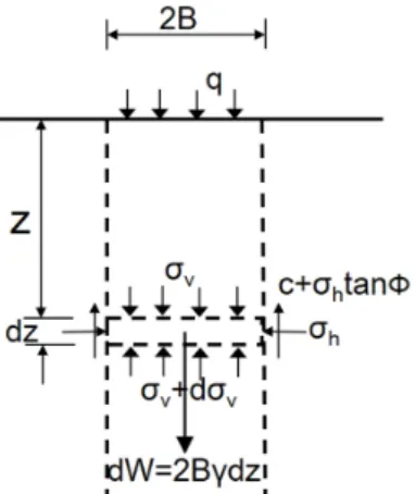
Terzaghi (1943) developed an arching formula that considers the force equilibrium of the differential area between two vertical surfaces, as shown in Fig. 1.
∴ ・tan ・ tan tan
(1)
Fig. 1. Diagram illustrating the assumptions for computing pressure between two vertical sliding surfaces
Fig. 2. Schematic of load transfer (arching) in 3D tunnel excavation conditions
For z=∞ and surcharge pressure q=0 on the ground surface,
・tan ・
(2)
where 2B is the width of yielding strip, γ is the unit weight, c is the cohesion, ϕ is the friction angle, and K is the earth pressure coefficient. However, Terzaghi formula is limited to 2D vertical sliding surface conditions and therefore it is difficult to apply the formula to 3D tunnel excavation and inclined sliding surface conditions.
The proposed 3D arching formula in this study considers the effects of ground properties and inclined sliding con- ditions in both the transverse and longitudinal directions as well as 3D tunnel excavation conditions (Fig. 2). A sliding surface does not generally form a consistent sliding angle from the part of deflection to the ground surface,
and the inclined sliding angle can differ for various orientations. Despite the new considerations, it is still assumed that the inclined sliding angle is consistent, regardless of the depth and orientation of the sliding surface. An arching theory that considers the effects of depth and orientation of the sliding angle could be developed by considering a function that reflects the influences of depth and orientation (Son, 2017). However, it would be very complicated and require a numerical method, so it is left for future work.
The arching formula for 3D conditions was derived using Terzaghi’s assumptions of homogeneous, isotropic, and semi-infinite soil. As shown in Fig. 3, the force equilibrium in the differential zone between the sliding surfaces with the angles of α1 and α2 was considered to incorporate the inclined sliding surfaces in 3D tunnel excavation conditions. Eq. (5) can be used to assess the vertical stress in various 3D ground and excavation con- ditions with inclined sliding surfaces in both the transverse and longitudinal directions. The equation is obtained by considering the force equilibrium (eq. (3)) of the differential zone in the depth direction (z) and the stress transfor- mation (eq. (4)), followed by rearranging, integrating, and solving for the stress. No infinitesimal values such as dz2 were considered to derive the expanded formula.
・
tan
tan tan ・tan
tan
tan
tan ・tan
Fig. 3. Diagram illustrating assumptions for computing pressure in 3D excavation conditions with inclined sliding surfaces at angles of α1 and α2
tan
tan
tan ・
tan tan
tan ・
tan tan
・
tan tan
・
tan tan
tan
tan tan
・tan
tan tan
(3)
cos
cos (4)
∴
tan tan
tan tan
tan tan ・ tan ・ tan
×
tan tan tan ・tan
・ ・
tan
・
tan
tan tan tan ・tan
・ ・
tan
・
tan
(5)where A =
tan tan tan ・tan
tan
tan tan
cos
tan
tan tan
cos
,In the longitudinal and transverse directions, c1 and c2 are the cohesion, ϕ1 and ϕ2 are the friction angles, K1 and K2 are the earth pressure coefficients, and α1 and α2 are the inclination angles of the sliding surface, respectively (Fig. 3).
3. Validation of the expanded formula
The expanded formula was validated in different ways.
The analytical validation of the formula was performed as follows:
Validation 1:
If z=0, α1=α2=90°, L=∞, K1=K2=K, c1=c2=c, and ϕ1= ϕ2=ϕ, ・tan ・tan・ , o.k
Validation 2:
If z=H=∞ with all other conditions the same as in Validation 1,
tan
∵ ∞
・ ・tan ・tan ・ , o.k
The expanded arching formula was also validated by comparison with 3D experimental test results (Adachi et al., 2003). The experimental tests were carried out through three-dimensional trapdoor tests with a vertical sliding surface and constant width. The change in the vertical stress on the trapdoors was examined by varying the ratio of the overburden height (H) to the trapdoor width (D) and lowering the six trapdoors arranged in the longitudinal direction one after another. The vertical stress (σv) measured on the first trapdoor for different H/D ratios and different stages was reported in terms of the normalized stress with respect to the initial vertical stress (σvo). The experimental
Fig. 4. Comparison with experimental test results
(a) 2B=2m (b) 2B=6m (c) 2B=10m
Fig. 5. Effect of excavation width (2B) and longitudinal excavation length (2L, L=half excavation length) under varying inclination angles (α1 and α2) (H=20m, γ=18kN/m3, c1=c2=0, ϕ1=ϕ2=35°, q=0, K1=K2=1)
results were compared with those from the derived formula for the same conditions (Fig. 4). The comparison shows quite similar results and trends, which further validates the derived formula. Both the analytical and experimental validations of the expanded formula justify its use for extended parametric studies of various conditions.
4. Analysis of the effects of various conditions and comparison of the results
The expanded 3D arching formula was used for para- metric studies under various inclination angles (α1, α2) of the sliding surface, excavation widths and lengths, ground properties condition, and surcharge pressure conditions.
The change of the vertical stress was examined under different conditions, and the results were compared with those of Terzaghi. Fig. 5 compares the vertical stresses induced with different excavation widths (2B). In the Terzaghi formula, the longitudinal excavation length is always infinite. the vertical stress increased gradually as the excavation width and length increased for the same
inclination angle. However, the vertical stress decreased as the inclination angle decreased. The effect of the in- clination angle became more prominent with increased excavation width.
As the angle (α2) in the transverse direction decreased, the effect of the inclination angle (α1) in the longitudinal direction again increased, but it decreased as the excavation length increased. When L exceeded about 100 m, the change in vertical stress became small, regardless of the inclination angle. The model test by Adachi el al. (2003) showed similar results and trends. The results indicate that the vertical stress is significantly affected by both the excavation width and length as well as the inclination angle of the sliding surface.
Fig. 6 compares the vertical stresses induced with different excavation depths (H) and longitudinal excava- tion lengths (2L) under an excavation width (2B) of 6 m.
The vertical stress for the same inclination angle increased gradually as the excavation depth and length increased, but the stress change decreased as the excavation depth increased. The effect of the inclination angle became more prominent with shallow excavation depth. As the transverse angle α2 decreased, the effect of the longitudinal inclina- tion angle α1 increased, but the effect decreased as the excavation length increased.
Fig. 7 compares the vertical stress results for different cohesion (c1 and c2) and longitudinal excavation length (2L) for the case of Fig. 5b. As the cohesion increased, the vertical stress decreased, but the stress increased with the excavation length. The vertical stress was more affected by the cohesion in the transverse direction and a low excavation length. Furthermore, the vertical stress could
(a) H=10m (b) H=2m (c) H=30m
Fig. 6. Effect of excavation depth (H) and longitudinal excavation length (2L, L=half excavation length) under varying inclination angles (α1 and α2) (2B=6m, γ=18kN/m3, c1=c2=0, ϕ1=ϕ2=35°, q=0, K1=K2=1)
(a) c1=c2=10kN/m2 (b) c1=c2=30kN/m2
(c) c1=10kN/m2, c2=30kN/m2 (d) c1=30kN/m2, c2=10kN/m2
Fig. 7. Effect of cohesion (c) and longitudinal excavation length (2L, L=half excavation length) under varying inclination angles (α1 and α2)
be less than 0 at a high cohesion and low excavation length, which implies that there is no vertical stress. The effect of the longitudinal inclination angle α1 increased as the transverse angle α2 decreased, but the effect decreased as the excavation length increased.
Fig. 8 compares the results for different friction angles (ϕ1 and ϕ2) and longitudinal excavation lengths (2L) for the case of Fig. 5b. The induced vertical stress and the effect of the inclination angle decreased with increasing friction angle. As observed in the cohesion results, the vertical stress was more affected by the friction angle in the transverse direction and at a low excavation length.
The effect of the longitudinal inclination angle α1 was
similar to that in the case of cohesion. The results indicate that the vertical stress in a trapdoor problem is inter- actively affected by the combination of the excavation, sliding, and ground properties conditions.
Fig. 9 compares the vertical stresses induced with different values of the earth pressure coefficient (K) and longitudinal excavation length (2L) for the case of Fig. 5b.
When K2 was increased to 2, the vertical stress decreased significantly, and the effect was bigger for the longer longitudinal excavation length and the higher inclination angle. As K1 was increased to 2, the vertical stress decreased at low excavation length, but the stress did not change much when K1 was increased to 2 compared to
(a) ϕ1=ϕ2=35° (b) ϕ1=ϕ2=45°
(c) ϕ1=35°, ϕ2=45° (d) ϕ1=45°, ϕ2=35°
Fig. 8. Effect of friction angle (ϕ) and longitudinal excavation length (2L, L=half excavation length) under varying inclination angles (α1 and α2)
(a) K1=K2=1 (b) K1=1, K2=2 (c) K1=2, K2=1
Fig. 9. Effect of earth pressure coefficient (K) and longitudinal excavation length (2L, L=half excavation length) under varying inclination angles (α1 and α2)
(a) q=0(b) q=50kN/m2 (c) q=100kN/m2
Fig. 10. Effect of surcharge pressure (q) and longitudinal excavation length (2L, L=half excavation length) under varying inclination angles (α1 and α2)
K1=K2=1 with L of 100 m or more. These results indicate that the earth pressure coefficient of the ground directly affects the maximum shear strength induced on the sliding surface interacting with both excavation and sliding con-
ditions.
Fig. 10 compares the results for different ground surcharge pressures (q) and longitudinal excavation lengths (2L) for the case of Fig. 5b. The vertical stress increased as the
ground surcharge pressure increased, and the effect was more prominent at low inclination angle and excavation length. The effects of the excavation length and inclination angle decreased as the ground surcharge pressure increased.
As the excavation length increased, the effect of the incli- nation angle (α1) in the longitudinal direction decreased.
5. Conclusions
The following conclusions were drawn from this study:
(1) The study further expanded a previous 3D arching formula by considering the effects of ground properties and inclined sliding conditions in both the transverse and longitudinal directions considering anisotropic ground conditions, as well as 3D tunnel excavation conditions. The expanded formula was validated by both an analytical method and comparison with experi- mental test results.
(2) Extended parametric studies were conducted with the expanded formula to examine the changes in vertical stress for various ground properties, inclined sliding, excavation, and surcharge pressure conditions. The results indicated that vertical stress can be significantly affected by the combination of the excavation, sliding, ground properties, and surcharge conditions.
(3) The vertical stress increased as the excavation width and length increased, the inclination angle increased, the cohesion and friction angle decreased, the earth pressure coefficient decreased, and the surcharge pressure increased. Under the conditions examined, the stress was more affected at low excavation lengths and by the ground properties in the transverse direction.
(4) The expanded formula could more realistically represent arching phenomena that occur in the field, where inclined sliding surfaces can form, definite longitudinal excavation lengths form during excavation process, and different ground properties can occur in different directions due to either natural deposits or ground improvements. The results from this study could pro- vide useful information for investigating practical arching effects in the field, as well as improve the understanding of various arching phenomena.
References
1. Adachi, T., Kimura, M., and Kishida, K. (2003), “Experimental Study on the Distribution of Earth Pressure and Surface Settlement through Three-dimensional Trapdoor Tests”, Tunnelling and Underground Space Technology, Vol.18(2-3).
2. Adachi, T., Kimura, M., Kishida, K., Kosaka, K., and Sakayama, Y. (1999), “The Mechanical behavior of Tunnel Interaction through Three Dimensional Trapdoor Tests (in Japanese)”, J. Geotech. Eng., JSCE 638/III-49, pp.285-299.
3. Ahmadi, A. and Hosseininia, E.S. (2013), “An Experimental Investi- gating the Width and Height of a Stable Arch Formed in Granular Materials by Using a New Developed Trapdoor Apparatus”, Conf.
on International Civil, Structural and Environmental Engineering ACSEE, Zurich, Switzerland, pp.20-24.
4. Bierbaumer, A. (1913), Die Dimensionierung des Tunnelmauerwerkes, Leipzig, W. Engelmann.
5. Cain, W. (1916), Earth Pressure, Retaining Walls and Bins. New York, John Wiley & Sons, Inc.
6. Caquot, A. (1934), Equilibre des Massifs Ii Frottement Interne, Paris, GauthierVillard.
7. Chau, H.Y. and Bolton, M.D. (2006), “The Use of Centrifuge Tests in the Study of Arching”, Physical modeling in geotechnics-6th ICPMG’06, pp.1075-1080.
8. Chen, R.P., Huang, W.Y., and Tseng, C.T. (2011), “Stress Redistri- bution and Ground Arch Development During Tunneling”, Tunneling and Underground Space Technology, Vol.26, pp.228-235.
9. Chevalier, B., Combe, G., and Villard, P. (2012), “Experimental and Discrete Element Modeling Studies of the Trapdoor Problem:
Influence of the Macro-mechanical Frictional Parameters”, Acta Geotechnica, Vol.7(1), pp.15-39.
10. Chevalier, B. and Otani, J. (2010), “3-D Arching Effect in the Trap-Door Problem: A Comparison between X-Ray CT Scanning and DEM Analysis”, Proc., GeoFlorida 2010, pp.570-579.
11. Costa, Y.D., Zornberg, J.G., Bueno, B.S., and Costa, C.L. (2009),
“Failure Mechanism in Sand Over a Deep Active Trapdoor”, J.
of Geotech. Geoenviron. Engr., Vol.135(11), pp.1741-1753.
12. Engesser, F. (1882), “Über den Erddruck Gegen Innere Stützwände”, Deutsche Bauzeitung, Vol.16, pp.91-93.
13. Evans, C. H. (1983). An examination of arching in granular soils, S.M. thesis, MIT, Cambridge, MA.
14. Falaknaz, N., Aubertin, M., and Li, L. (2015), “Numerical Investi- gation of the Geomechanical Response of Adjacent Backfilled Stopes”, Canadian Geotecchnical Journal, Vol.52(10), pp.1507-1525.
15. Getzler, Z., Gellert, M., and Eitan, R. (1970), “Analysis of Arching Pressures in Ideal Elastic Soil”, J. of the Soil Mechanics and Foundations Division, ASCE, Vol.96, No.SM4, pp.1357-1372.
16. Iglesia, G.R., Einstein, H.H., and Whitman, R.V. (2014), “Investi- gation of Soil Arching with Centrifuge Tests”, J. Geotech. Geoenviron.
Eng., Vol.140(2), pp.1-13.
17. Koutsabeloulis, N.C. and Griffiths, D.V. (1989), “Numerical Modeling of the Trapdoor Problem”, Geotechnique, Vol.39, No.1, pp.77-89.
18. Ladanyi, B. and Hoyaux, B. (1969), “A Study of the Trapdoor Problem in a Granular Mass”, Canadian Geotechnical Journal, Vol.6(1), pp.1-15, DOI: 10.1139/t69-001.
19. Lee, Y-J and Lee, S-D (2010), “Longitudinal Arching Effect of an Under-passing Tunnel on the Existing Tunnel Undergoing a Load of Upper Structures”, J. of Korean Tunnelling and Underground
Space Assoc., Vol.12(6), pp.417-427.
20. Li, L., Aubertin, M., and Belem, T. (2005), “Formulation of a Three Dimensional Analytical Solution to Evaluate Stresses in Backfilled Vertical Narrow Openings”, Canadian Geotechnical Journal, Vol.
42(6), pp.1705-1717.
21. Li, L., Dube, J., and Aubertin, M. (2013), “An Extension of Marston’s Solution for the Stresses in Backfilled Trenches with Inclined Walls”, Canadian Geotechnical Journal, Vol.42(6), pp.1705-1717.
22. Marston, A. (1930), “The theory of external loads on closed conduits in the light of the latest experiments”, Bulletin 96, Iowa State University Engineering Experiment Station, Ames, Iowa.
23. McNulty, J.W. (1965), An Experimental Study of Arching in Sand, Ph.D. Thesis in Civil Engineering, University of Illinois.
24. Nielson, F.D. (1966), Soil structure arching analysis of buried flexible structures, PhD Thesis, University of Arizona, faculty of Civil Engineering.
25. Nunes, M.A. and Meguid, M.A. (2009), “A Study on the Effects of Overlying Soil Strata on the Stresses Developing in a Tunnel”, Tunnelling and Underground Space Technology, Vol.24, pp.716-722.
26. Ono, K. and Yamada, M. (1993), “Analysis of Arching Action in Granular Mass”, Geotechnique, Vol.43(1), pp.105-120.
27. Paikowsky, S.G., DiRocco, K.J., and Xi, F. (1993), “Interparticle Contact Force Analysis and Measurements Using Photoelastic Tech- niques”, 2nd International Conference on Discrete Element Methods, MIT, Cambridge, Massachusetts, pp.449-461.
28. Paikowsky, S.G. and Hsienjen, S.T. (2002), “Experimental Exami- nation of the Arching Effect Mechanism on the Micro Level”, Proceeding of 3thInternational DEM conference, New Mexico, pp.
222-228.
29. Pardo, G.S. and Sáez, E. (2014), “Experimental and Numerical Study of Arching Soil Effect in Coarse Sand”, Computers and Geotechnics, Vol.57, pp.75-84.
30. Pirapakaran, K. and Sivakugan, N. (2007), “Arching Within Hydraulic Fill Stopes”, Getech. Gelo. Eng., Vol.25, pp.25-35.
31. Sakaguchi, H. and Ozaki, E. (1992), “Analysis of the Formation of Arches Plugging the Flow of Granular Materials”, Proceedings of the 2nd International Conference on Discrete Element Method, MIT, Cambridge, Massachusetts, pp.153-163.
32. Santichaianaint, K. (2002), Centrifuge modelling and analysis of active trapdoor in sand, Ph.D. thesis, Univ. of Colorado at Boulder.
33. Sardrekarimi, J. and Abbasnejad, A.R. (2010), “Arching Effect in Fine Sand due to base Yielding”, Canadian Geotechnical Journal, Vol.47(3), pp.366-374, DOI: 10.1139/T09-107.
34. Singh, S., Shukla, S.K., and Sivakugan, N. (2011), “Arching in Inclined and Vertical Mine Dtopes”, Geotech. Geol. Eng., Vol.29, pp.685-693.
35. Sivakugan, N., Widisinghe, S., and Wang, V.Z. (2014), “Vertical Stress Determination Within Backfilled Mine Stopes”, Int. J. of Geo. Mech., Vol.14, No.5, pp.1-5.
36. Spangler, M.G. and Handy, R.L. (1982), “Loads on Underground Conduits”, Soil Engineering, New York, pp.727-763.
37. Son, M. (2017), “Three-Dimensional Expansion of the Terzaghi Arching Formula Considering Inclined Sliding Surfaces and Exami- nation of Its Effects”, International journal of geomechanics, Vol.
17(7), pp. 06016043: 1-8.
38. Terzaghi, K. (1943), Theoretical soil mechanics, John Wiley and Sons, New York.
39. Vardoulakis, I., Graf, B., and Gudehus, G. (1981), “Trap-door
Problem with Dry Sand: A Statical Approach based Upon Model Test Kinematics”, International journal for numerical and analytical methods in geomechanis, Vol.5(1), pp.57-78.
40. Völlmy, A. (1937), Eingebettete Rohre. Mitt. Inst. Baustatik, Eidgen.
Tech. Hochschule, Zurich, Mitt. No.9.
41. Vorster, T. E. B. (2005), The effects of tunnelling on buried pipes, PhD thesis, Engineering Department, Cambridge University.
42. Yim, I-J and Lee, S-D (2017), “Experimental Study on the Ground Arching Depending on the Deformation Type of the Crown in the Shallow Tunnel”, J. of Korean Tunnelling and Underground Space Assoc., Vol.19(5), pp.733-747.
Received : August 16th, 2018 Revised : December 3rd, 2018 Accepted : December 4th, 2018
List of symbols:
σv : Vertical stress
σn1: Normal stress on the sliding surface in the longitudinal direction
τn1: Shear stress on the sliding surface in the longitudinal direction
σn2: Normal stress on the sliding surface in the transverse direction
τn2: Shear stress on the sliding surface in the longitudinal direction
2B : Width of yielding strip in the transverse direction (width of excavation)
2L : Length of yielding strip in the longitudinal direction (length of excavation)
H : Depth of yielding strip (depth of excavation) z : Arbitrary depth
α1 : Inclination angle of sliding surface in the longitudinal direction
α2 : Inclination angle of sliding surface in the transverse direction
γ : Soil unit weight
ϕ1 : Soil friction angle in the longitudinal direction ϕ2 : Soil friction angle in the transverse direction c1 : Soil cohesion in the longitudinal direction c2 : Soil cohesion in the transverse direction
K1: Earth pressure coefficient in the longitudinal direction K2: Earth pressure coefficient in the transverse direction q : Surcharge pressure on the ground surface