Journal of the Korean Society of Surveying, Geodesy, Photogrammetry and Cartography Vol. 36, No. 6, 443-449, 2018
https://doi.org/10.7848/ksgpc.2018.36.6.443
다중 2D 레이저 스캐너 시스템의 외부 표정요소 캘리브레이션을 위한 시뮬레이션 기반 표적 배치 결정 기법
Simulation based Target Geometry Determination Method for Extrinsic Calibration of Multiple 2D Laser Scanning System
주성하1)· 윤상현2) · 박상윤3) · 허준4)
Ju, Sungha · Yoon, Sanghyun · Park, Sangyoon · Heo, Joon
Abstract
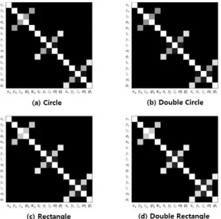
Acquiring indoor point cloud, using SLAM (Simultaneous Localization and Mapping) based mobile mapping system, is an element progress for development of as-build BIM (Building Information Model) for the maintenance of the building. In this research we proposed a simulation-based target geometry determination for extrinsic calibration of multiple 2D laser scanning mobile system. Four different types of calibration sites were designed: (1) circle type; (2) rectangle type; (3) double circle type; and (4) double rectangle type. Based on the measurement values obtained from each simulated calibration site geometry, least squares solution based extrinsic calibration was derived. As a result, the rectangle type geometry is most suitable for extrinsic calibration of this system. Also, correlation values between extrinsic calibration parameters were high, and calibration results were distinct according to the calibration sites.
Keywords : Extrinsic Calibration, 2D Laser Scanning System, Calibration Design, Simulation
초 록
SLAM (Simultaneous Localization and Mapping) 기반 모바일 매핑 시스템을 활용한 실내 공간의 포인트 클라 우드 취득은 건축물의 유지, 관리를 위한 as-built BIM (Building Information Model) 구축의 기초 공정이다. 본 연
구에서는 다중 2D 레이저 스캐너로 구성된 모바일 매핑 시스템의 구축을 위한 시뮬레이션 기반 검정(calibration)
표적의 구조 결정 방법을 제안하였다. 2D 레이저 스캐너의 외부 표정요소 검정을 위해 (1) 원형, (2) 사각형, (3) 이중
원형, (4) 이중 사각형 형태의 표적을 구성하였다. 시뮬레이션을 통해 얻어진 각 표적 관측 값을 토대로, 최소제곱법
기반의 외부 표정요소 검정을 수행하였다. 그 결과 사각형 형태의 표적 구조가 주어진 시스템의 검정에 가장 적합
한 형태임을 확인하였다. 또한 외부 표정요소 간의 높은 상관성을 확인할 수 있었으며, 표적의 구조에 따른 외부 표
정요소의 검정 결과가 상이한 것으로 나타났다.
핵심어 : 외부 표정요소 검정, 2D 레이저 스캐닝 시스템, 검정 설계, 시뮬레이션
443 ISSN 1598-4850(Print) ISSN 2288-260X(Online) Original article
Received 2018. 09. 12, Revised 2018. 10. 12, Accepted 2018. 11. 13
1) Dept. of Civil and Environmental Engineering, Yonsei University (E-mail: [email protected]) 2) Dept. of Civil and Environmental Engineering, Yonsei University (E-mail: [email protected]) 3) Dept. of Civil and Environmental Engineering, Yonsei University (E-mail: [email protected])
4) Corresponding Author, Member, Dept. of Civil and Environmental Engineering, Yonsei University (E-mail: [email protected])
This is an Open Access article distributed under the terms of the Creative Commons Attribution Non-Commercial License (http://
creativecommons.org/licenses/by-nc/3.0) which permits unrestricted non-commercial use, distribution, and reproduction in any medium, provided the original work is properly cited.
Journal of the Korean Society of Surveying, Geodesy, Photogrammetry and Cartography, Vol. 36, No. 6, 443-449, 2018
444
1. 서 론
최근 기 준공된 다양한 토목·건축 구조물의 생애주기 관리 를 위해 준공 BIM (as-built BIM)이 각광받고 있다(Golparvar- Fard et al., 2011; Carbonari et al., 2015; P tr ucean et al., 2015).
As-built BIM은 구조물의 3차원 데이터 취득, 유지·관리에 활 용 가능한 모델 구축의 과정을 거쳐 제작되며 센서의 활용, 모델 구축 방식과 관련하여 다양한 연구가 진행되고 있다(Dore and Murphy, 2014; Hong et al., 2015; Yang et al., 2016). 특히, 지상 레 이저 스캐너(terrestrial laser scanner)는 높은 밀도의 3차원 데이 터의 취득이 가능하므로 as-built BIM 구축에 많이 활용되고 있 지만 (Hong et al., 2012), 대규모 실내 공간에 대한 3차원 데이터 취득을 위해서는 장비의 이동과 데이터 정합과 같은 후처리 과 정이 필요하다. 이러한 지상 레이저 스캐너의 한계를 극복하기 위해, 자신의 위치와 주변 환경에 대한 정보를 동시에 취득하는 SLAM (Simultaneous Localization and Mapping) 기술을 활용한 레이저 스캐너 기반 모바일 매핑 시스템(MMS: Mobile Mapping System)이 연구되고 있다 (Jung et al., 2015b; Wang et al., 2014).
레이저 스캐너 기반 모바일 매핑 시스템 구축은 as-built BIM 구축에 필요한 고정밀 3차원 데이터를 취득하기 위하여, 다수 의 레이저 스캐너 및 모바일 플랫폼 간의 검정(calibration) 과정 이 필수적이다. 레이저 스캐너 검정은 내부 표정요소(intrinsic parameter)와 외부 표정요소(extrinsic parameter)의 검정으로 구 분된다. 다중 레이저 스캐너를 활용한 시스템의 경우 센서 간 위 치(lever-arm) 및 방향(boresight)에 대한 외부 표정요소의 검정 이 필요하다. Choi et al. (2016) 은 두 대의 2D 레이저 스캐너가 직 교한 평면들을 스캔하는 경우, 두 스캔 라인이 서로 같은 평면 위 에 있거나 서로 직각이라는 조건을 이용하여 외부 표정요소의 검정을 수행하였다. Fernández-Moral et al. (2015) 은 세 대의 2D 레이저 스캐너가 동일 평면에 대한 데이터를 취득하였을 때, 각 스캔 라인들이 모두 같은 평면 위에 있다는 조건을 활용한 외부 표정요소 검정을 수행하였다. 그러나, 기존 연구들은 레이저 스 캐너들이 같은 평면을 스캔 할 수 있을 때만 적용이 가능하다는 한계점이 존재하며, 센서 간 상대 위치 및 방향에 따른 외부 표정 요소의 분석이 수행되지 않았다.
본 연구에서는 기 개발된 다중 2D 레이저 스캐너 기반 3차 원 포인트 클라우드 취득 시스템 (Jung et al., 2015b)의 외부 표 정요소 결정을 위한 검정 표적의 최적 구조를 시뮬레이션을 통 해 평가하였다. 시뮬레이션을 통해 4가지의 검정 표적 구조를 구 성하였고, 측지 네트워크의 관측 망 디자인 개념을 활용하였으 며, 외부 표정요소 간의 상관성을 확인하고 최적의 표적 구조를 결정하였다.
2. 연구 방법
2.1 3차원 포인트 클라우드 취득 시스템
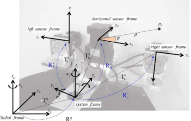
본 연구진은 기존 연구 인 Jung et al. (2015a), Jung et al. (2015b) 를 통해 3대의 Hokuyo UTM-30LX 2D 레이저 스캐너와 모바일 플랫폼으로 구성된 3차원 포인트 클라우드 취득 시스템을 구축 하였다. 기 개발된 시스템의 주행 성능 향상을 위하여 기존 모바 일 플랫폼 보다 높은 동력을 가진 모바일 플랫폼으로의 교체를 진행하였으며, 상단 부 레이저 스캐너의 기하 구조는 기존의 형 태를 유지하였다(Fig. 1). 레이저 스캐너는 시스템의 진행 방향과 수평으로 1대, 수직으로 2대 설치되어 있으며, 수평 방향 센서는 SLAM의 입력 데이터로, 수직 방향 센서는 3차원 포인트 클라 우드의 구축에 활용된다. 각 센서 (H-수평 센서, L-좌측 수직 센 서, R- 우측 수직 센서) 로부터 취득되는 포인트 (P)에 대한 센서 중심 좌표계 (s) 및 글로벌 좌표계 (g)로의 변환은 다음 Fig. 2와 Eqs. (1) and (2)와 같다(Jung et al., 2015a).
Fig. 1. Laser scanning system for acquiring 3D point cloud
Fig. 2. Design for coordinate system of multiple 2D laser scanning system (Jung et al., 2015a)
:
: :
s s
s h h h
s s
s l l l
s s
s r r r
H P R P T L P R P T R P R P T
= +
= +
= +
, , , , , , , ,
, , , , , , , , , , , , , ,
, , , , , , , ,
cos sin 0 cos 0 sin 1 0 0
where sin cos 0 0 1 0 0 cos sin and , is
0 0 1 sin 0 cos 0 sin cos
rotati
h l r h l r h l r h l r
s s s
h l r h l r h l r h l r h l r h l r h l r
h l r h l r h l r h l r
R R T
κ κ ϕ ϕ
κ κ ω ω
ϕ ϕ ω ω
⎡ ⎤ ⎡ ⎤
⎡ − ⎤
⎢ ⎥ ⎢ ⎥
⎢ ⎥
=⎢ ⎥⎢ ⎥ ⎢ − ⎥
⎢ ⎥ ⎢ ⎥
⎢ ⎥ −
⎣ ⎦ ⎣ ⎦ ⎣ ⎦
on, translation vector from each sensors to center of the scanning system
: : :
h l r
g g
g s s s
g g
g s s s
g g
g s s s
H P R P T L P R P T R P R P T
= +
= +
= +
cos sin 0
where sin cos 0 and is translation vector from global frame to center of the scanning system
0 0 1
s s
g g
s s s s
R T
κ κ
κ κ
⎡ − ⎤
⎢ ⎥
= ⎢ ⎥
⎢ ⎥
⎣ ⎦
s, , h l r
T Rh l rs, , , ,
s s s
h l r
T T T
~ ( , ) (0,3 )
e μ σ = mm
cos (cos cos cos sin )
sin (cos sin sin sin cos cos cos sin sin sin )
sin (cos cos cos sin )
cos (cos sin sin sin
x g g s s t s s t s offset
g s s t s s s t s s t s s s t s
y g g s s t s s t s offset
g s s t s s
P x x y x v
x x y y y
P y x y x v
x
κ ϕ κ ϕ κ
κ ϕ κ ω ϕ κ ω κ ω ϕ κ
κ ϕ κ ϕ κ
κ ϕ κ ω ϕ
= + − + +
− + + − +
= + − + +
+ + cos cos cos sin sin sin )
sin sin cos sin cos sin cos cos sin sin
s t s s t s s s t s
z g s s t s s s t s s t s s s t s offset
x y y y
P z x x y y y h
κ ω κ ω ϕ κ
ϕ κ ω ϕ κ ω κ ω ϕ κ
+ − +
= + − + + + +
offset, offset
v h T T T R R Rhs, , , , , ls rs hs ls rs Rh l rs, , Jξ = +Y υ
(1)