Vol.19, No.2, (2017), pp.1~8 https://doi.org/10.9714/psac.2017.19.2.001
```
1. INTRODUCTION
HTS (High Temperature Superconducting) power application equipment is very effective for energy saving and expected as one of key technologies for future prosperous society. One of their superior properties comparing to Low Temperature Superconducting equipment can be cooled by liquid nitrogen (LN). First of all, LN temperature at atmospheric pressure is 77.4 K and Liquid helium temperature at atmospheric pressure is 4.2 K.
Required energy of nitrogen liquefaction is about 1/9 of required energy of helium liquefaction. Each COP (coefficient of performance) of maintaining each temperature by ideal Carnot refrigerator is 0.345 and 0.0142, respectively. So, usage of LN means a very economical decision. Furthermore, the latent heat of LN is about ten times larger than the latent heat of liquid helium.
This property makes LN handling easier as a coolant.
Nitrogen is very abundant and cheaper resource. Then, LN is a very suitable coolant for HTS equipment.
In this article, sub-cooled LN cooling system is mentioned mainly. A couple of examples are introduced and the article shows how to design those systems and how to maintain their temperature lower than 77 K.
Sub-cooled LN has better points as a coolant, comparing to saturated LN, as shown in the below;
1. Sub-cooled LN can maintain lower temperature than saturated LN temperature. And critical current of HTS material is increased at lower temperature.
2. Sub-cooled LN can be pressurized to higher atmospheric pressure. And HTS equipment can be set in higher pressure circumstance. It prevents from invasion of air component, especially, water vapor and carbon dioxide.
3. Those components are sometimes solidified in the equipments and make damage into them.
4. Nitrogen gas bubbles are eliminated immediately in sub-cooled LN, and dielectric strength of the coolant is kept a proper value.
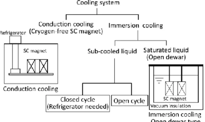
2. CRYOGENIC SYSTEM CATEGORIZATION Fig. 1 shows cryogenic system categorization. There are two large categories in cooling system for HTS equipment. One is immersion cooling method and the other is conduction cooling method.
Each system has benefits. In the conduction cooling method, HTS equipment is connected with refrigerator cold head through good thermal conductive material like copper and/or aluminum. The operated temperature depends on cooling power of the refrigerator and usually the operate temperature is lower than 77 K. it is better for HTS material.
Fig. 1. Cryogenic system categorization.
Cryogenic cooling system for HTS cable
Shigeru Yoshida*
Taiyo Nippon Sanso, Tsukuba, Japan
(Received 16 May 2017; revised or reviewed 16 June 2017; accepted 17 June 2017)
Abstract
Recently, Research and development activity of HTS (High Temperature Superconducting) power application is very progressive worldwide. Especially, HTS cable system and HTSFCL (HTS Fault current limiter) system are proceeding to practical stages. In such system and equipment, cryogenic cooling system, which makes HTS equipment cooled lower than critical temperature, is one of crucial components. In this article, cryogenic cooling system for HTS application, mainly cable, is reviewed.
Cryogenic cooling system can be categorized into conduction cooling system and immersion cooling system. In practical HTS power application area, immersion cooling system with sub-cooled liquid nitrogen is preferred. The immersion cooling system is besides grouped into open cycle system and closed cycle system. Turbo-Brayton refrigerator is a key component for closed cycle system. Those two cooling systems are focused in this article. And, each design and component of the cooling system is explained.
Keywords: Cooling system, Turbo-Brayton refrigerator, Sub-cooled liquid nitrogen, HTS (High Temperature Superconducting) cable
* Corresponding author: [email protected]
A vessel, in which HTS equipment is installed, is a simple vacuum chamber and makes the system compact.
On the other hand, heat transfer through conduction material needs usually lager temperature difference and there is also a temperature distribution inside HTS material body. The most serious problem of this method is a large temperature difference at each joint of HTS material, conduction material and refrigerator cold head.
In immersion cooling system, actual lowest temperature is limited by solidification temperature of the coolant, namely, LN freezing temperature, 63 K. Heat transfer mode is usually governed by convection and temperature difference is smaller than conduction heat transfer. Also, HTS material temperature can be almost uniform. Large amount of LN has enough heat capacity and latent heat energy. If the cryogenic system should have a trouble, LN can keep its cold temperature for reasonable time. In conduction cooling system, if once refrigerator should quit, immediately HTS material temperature is going up and it is hard to keep below its critical temperature.
Immersion cooling system can be defined into two methods by coolant conditions, which are sub-cooled condition and saturated condition, respectively. In this article, immersion cooling system with sub-cooled LN is focused. Saturated LN at atmospheric pressure is easy to handle and can be reserved in open dewar. Heat leak into saturated LN produces nitrogen bubble, and it weakens its dielectric strength [1,2]. Many researchers use saturated LN during checking HTS material properties, but sub-cooled LN must be used in actual equipment operation.
Nitrogen bubbles are disappeared immediately in sub-cooled LN.
3. OPEN CYCLE CRYOGENIC SYSTEM In the previous chapter, we talked about system with coolant and without coolant. In this chapter, cooling system with coolant is discussed. In other words, open cycle and closed cycle are reviewed. Here, “open” means that LN is dissipated and “closed” means non-consuming of LN. In generally, immersion cooling system for HTS application is operated at around 70 K. So, its design temperature is around 70 K.
Fig. 2 shows a historical open cycle cooling system made in 1996, and its cooling power is only 100 watt [3].
The cooling system was originally developed for THS transformer, but the principal idea can be used for cooling system of HTS cable. In Fig. 2, HTS transformer is set in the main cryostat and immersed in sub-cooled LN. The sub-cooled LN comes from the sub-cooler unit, which has a heat exchanger inside and is filled with saturated LN. The sub-cooled LN is produced in the heat exchanger in this unit. The saturated LN in the sub-cooler unit is evacuated by a vacuum pump and the LN temperature is reduced to be about 67 K. Pressurized LN flows inside the tube of the heat exchanger and its temperature becomes around 70 K.
In this system, saturated LN in the sub-cooled unit is consumed continuously and LN replenishment is needed.
Fig. 2. Open cycle cryogenic system.
Design procedure of the open cycle system is described briefly. The most important component is the heat exchanger. For a small system, coil tube type heat exchanger is easy and simple as shown in Fig. 2. The coil tube heat exchanger is very useful for small experiments in university laboratories and research institutes.
A basic heat exchanger design method is described below. Heat transfer coefficient outside a tube (o) can be calculated by boiling heat transfer equation, Rohsenow equation (1) [4].
Heat transfer coefficient inside a tube (i) can be calculated by convective heat transfer equation (2) with Colburn J-factor equation (3) [5]. Total allowable temperature difference (T) between saturated LN and sub-cooled LN is written as (4). Required cooling power (Q) is the same as heat transfer amount through outer tube face area and inner tube face area, respectively, and this relation is shown as (5). Those five equations are solved simultaneously to get temperature difference To value, temperature difference Ti value and tube coil heat exchanger length (L) in (5), respectively.
𝛼𝑜 𝜆
𝜎
𝑔 𝜌𝐿 − 𝜌𝑉 =𝑃𝑟−0.7 𝐶
𝛼𝑜 ∙ Δ𝑇𝑜 𝐿𝐻 ∙ 𝜌𝑉 ∙ 𝜐𝐿
𝜎 𝑔 𝜌𝐿 − 𝜌𝑉
0.67
𝜌𝑉 𝜌𝐿
0.67
(1)
α𝑖 =
4𝑀∙𝑗 ℎ∙𝐶𝑝𝜋∙ 𝐷𝑖2 ∙𝑃𝑟0.67 (2)
1
𝑗ℎ = 0.023 ∙ 𝑅𝑒−0.2 1 + 3.5 𝐷𝑖/𝐷ℎ (3) 1
∆𝑇𝑜 + Δ𝑇𝑖 = ∆𝑇 (4)
1
𝑄 = 𝛼𝑜 ∙ Δ𝑇𝑜 ∙ 𝐷𝑜 ∙ 𝐿 = 𝛼𝑖 ∙ Δ𝑇𝑖 ∙ 𝐷𝑖 ∙ 𝐿 (5) 1
Where αo is the outside heat transfer coefficient (W/m2K), αi is the inside heat transfer coefficient (W/m2K), ΔTo is the temperature difference between outer wall and saturated LN (K), ΔTi is the temperature difference between inner wall and sub-cooled LN (K), ΔT is the temperature difference between outer saturated LN and inner sub-cooled LN (K), LH is LN latent heat (J/kg), ρV is nitrogen gas density (kg/m3), ρL is LN density (kg/m3), is LN thermal conductivity (W/m K), σ is LN surface tension
(N/m) νL is LN coefficient of kinematic viscosity (m2/s ), Pr is Prandtl number, Re is Reynolds number, M is the LN flow rate (kg/sec), Cp is LN specific heat (J/kg K), Di is the tube inner diameter (m), Do is the tube outer diameter (m), Dh is the coil diameter (m), g is acceleration of gravity(9.8 m/sec2), C is the constant number (0.008 ), Q is the required cooling power (W) and L is the tube length (m).
A large scale cooling system can be designed by the same procedure as a small scale cooling system. Fig. 3 shows a flow diagram of a large scale open cycle cooling system. Fig. 4 (a) and (b) show photo-pictures of a large scale open cycle system whose cooling power is 2kW at 65 K [6]. The cooling system was installed for a HTS cable test facility of Furukawa Electric in China. Open cycle system is used worldwide, namely, China, Korea, USA and Europe, because its initial investment is smaller than closed cycle system.
Fig. 3. A flow diagram of a large scale open cycle cooling system.
a) A photo-picture of HTS cable system with a large scale open cycle cooling system.
b) A large scale open cycle cooling system.
Fig. 4. HTS cable system with a large scale open cycle cooling system.
In Korea, KEPCO has operated a larger system whose cooling power is 6 kW at around 69 K [7]. In German Ampa city project, 4 kW at 67 K cooling system has been operated for more than one year [8]. Usually, its cooling power is less than 10 kW. Open cycle system consumes a large amount of LN and there might be LN supply difficulty for a larger open cycle system whose cooling power is larger than 10 kW.
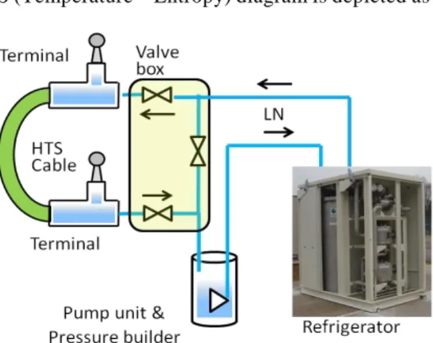
4. CLOSED CYCLEE CRYOGENIC SYSTEM Fig. 5 shows a schematic flow diagram of a closed cycle cooling system. LN circulation loop is the same as the open cycle cooling system and producing sub-cooled LN method is only different. In order to produce and/or cool sub-cooled LN, refrigerator is used in this system. A sub-cooler is usually installed inside a refrigerator cold box, and the sub-cooler works for heat exchanging between sub-cooled LN and refrigerator working fluid.
In closed cycle cooling system, a key component is a refrigerator. GM refrigerator is often used in a small system, whose cooling power is usually less than around 500 W.
For a larger system whose cooling power is larger than 1 kW, Stirling refrigerators and Turbo-Brayton refrigerators are adopted. Stirling refrigerator has relatively high efficiency, but periodic maintenance in a short term is required. Turbo-Bryaton refrigerator has been developed recently and expected a long term maintenance interval, which is at least three years [9-12]. This chapter describes Stirling cycle and Brayton cycle comparison, and turbo-Brayton refrigerator detail.
4.1 Carnot cycle
In refrigeration cycles, Carnot cycle is an ideal cycle and any refrigerator cannot overcome against Carnot efficiency. Stirling cycle efficiency is the same as Carnot cycle theoretically. Fig. 6 shows Carnot cycle schematically, and explains coefficient of performance (COP) definition. COP is defined as ratio of cooling power and required work energy. And COP is a very important value for refrigerator performance. Carnot cycle configure at T-S (Temperature – Entropy) diagram is depicted as a
Fig. 5. A schematic flow diagram of a closed cycle cooling system.
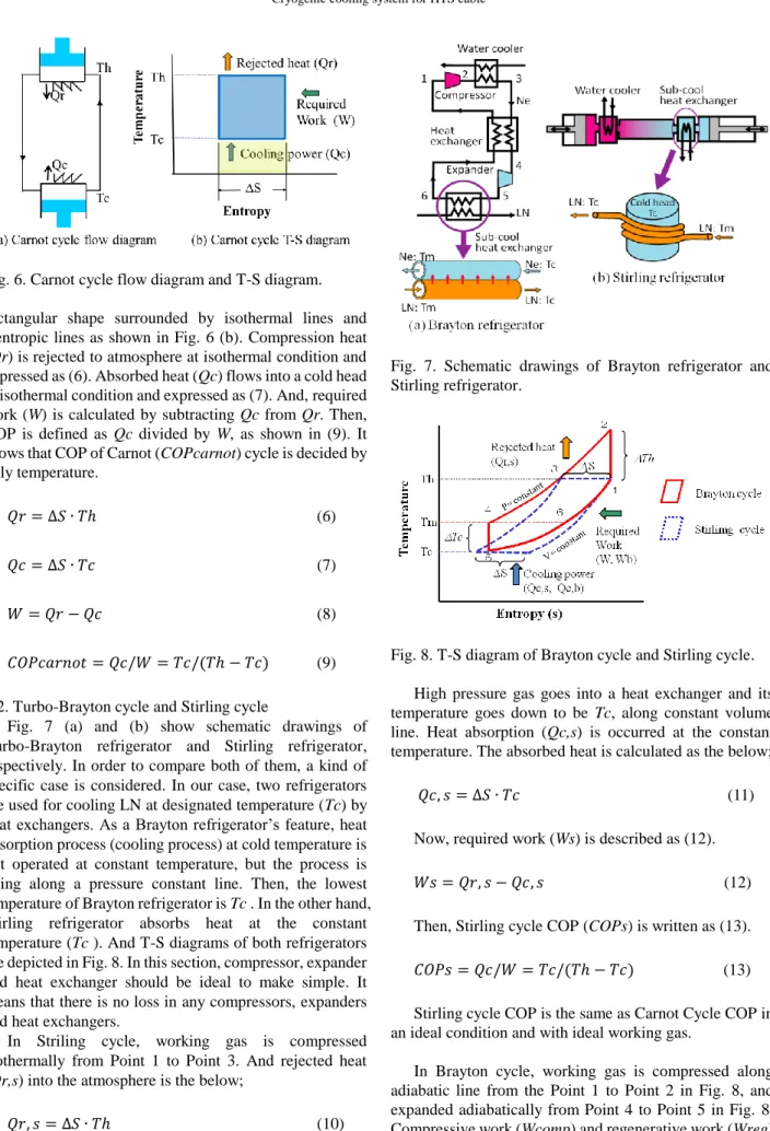
Fig. 6. Carnot cycle flow diagram and T-S diagram.
rectangular shape surrounded by isothermal lines and isentropic lines as shown in Fig. 6 (b). Compression heat (Qr) is rejected to atmosphere at isothermal condition and expressed as (6). Absorbed heat (Qc) flows into a cold head at isothermal condition and expressed as (7). And, required work (W) is calculated by subtracting Qc from Qr. Then, COP is defined as Qc divided by W, as shown in (9). It shows that COP of Carnot (COPcarnot) cycle is decided by only temperature.
𝑄𝑟 = ∆𝑆 ∙ 𝑇ℎ (6)
1
𝑄𝑐 = ∆𝑆 ∙ 𝑇𝑐 (7)
1
𝑊 = 𝑄𝑟 − 𝑄𝑐 (8)
1
𝐶𝑂𝑃𝑐𝑎𝑟𝑛𝑜𝑡 = 𝑄𝑐/𝑊 = 𝑇𝑐/(𝑇ℎ − 𝑇𝑐) (9) 1
4.2. Turbo-Brayton cycle and Stirling cycle
Fig. 7 (a) and (b) show schematic drawings of Turbo-Brayton refrigerator and Stirling refrigerator, respectively. In order to compare both of them, a kind of specific case is considered. In our case, two refrigerators are used for cooling LN at designated temperature (Tc) by heat exchangers. As a Brayton refrigerator’s feature, heat absorption process (cooling process) at cold temperature is not operated at constant temperature, but the process is going along a pressure constant line. Then, the lowest temperature of Brayton refrigerator is Tc . In the other hand, Stirling refrigerator absorbs heat at the constant temperature (Tc ). And T-S diagrams of both refrigerators are depicted in Fig. 8. In this section, compressor, expander and heat exchanger should be ideal to make simple. It means that there is no loss in any compressors, expanders and heat exchangers.
In Striling cycle, working gas is compressed isothermally from Point 1 to Point 3. And rejected heat (Qr,s) into the atmosphere is the below;
𝑄𝑟, 𝑠 = ∆𝑆 ∙ 𝑇ℎ (10)
1
Where, S is entropy difference shown in Fig. 8.
Fig. 7. Schematic drawings of Brayton refrigerator and Stirling refrigerator.
Fig. 8. T-S diagram of Brayton cycle and Stirling cycle.
High pressure gas goes into a heat exchanger and its temperature goes down to be Tc, along constant volume line. Heat absorption (Qc,s) is occurred at the constant temperature. The absorbed heat is calculated as the below;
𝑄𝑐, 𝑠 = ∆𝑆 ∙ 𝑇𝑐 (11)
1
Now, required work (Ws) is described as (12).
𝑊𝑠 = 𝑄𝑟, 𝑠 − 𝑄𝑐, 𝑠 (12)
1
Then, Stirling cycle COP (COPs) is written as (13).
𝐶𝑂𝑃𝑠 = 𝑄𝑐/𝑊 = 𝑇𝑐/(𝑇ℎ − 𝑇𝑐) (13) 1
Stirling cycle COP is the same as Carnot Cycle COP in an ideal condition and with ideal working gas.
In Brayton cycle, working gas is compressed along adiabatic line from the Point 1 to Point 2 in Fig. 8, and expanded adiabatically from Point 4 to Point 5 in Fig. 8.
Compressive work (Wcomp) and regenerative work (Wreg) by expander for a unit flow rate are described in the below, respectively.
𝑊𝑐𝑜𝑚𝑝 = 𝐶𝑝 ∙ ∆𝑇ℎ (14) 1
𝑊𝑟𝑒𝑔 = 𝐶𝑝 ∙ ∆𝑇𝑐 (15)
1
Where, Cp is specific heat at constant pressure.
Then, required work (Wb) for a unit flow rate is described as (16).
𝑊𝑏 = 𝑊𝑐𝑜𝑚𝑝 − 𝑊𝑟𝑒𝑔 = 𝐶𝑝 ∙ (∆𝑇ℎ − ∆𝑇𝑐) (16) 1
Compressed gas is cooled by air and/or water, and the temperature becomes ambient temperature (point 3). In order to cool high pressure gas, high pressure gas goes through a main heat exchanger, where gas temperature is reduced at constant pressure. Cold high pressure gas at temperature of Tm (point 4) is expanded adiabatically by an expander and the temperature goes down to the lowest temperature Tc (point 5), as described in the above. The coldest gas goes into a sub-cooler and absorbs heat from sub-cooled LN. Then, the temperature becomes to be Tm (point 6). The low pressure gas returns into the main heat exchanger and its temperature is resumed to be Th (point 1).
Between Point 5 and Point 6, absorbed heat amount (Qc,b) for a unit flow rate is expressed as (17).
𝑄𝑐, 𝑏 = 𝐶𝑝 ∙ ∆𝑇𝑐 (17)
1
Then, COP of Brayton cycle (COPb) is expressed as (18)
𝐶𝑂𝑃𝑏 = 𝑄𝑐, 𝑏/𝑊𝑏 = ∆𝑇𝑐/(∆𝑇ℎ − ∆𝑇𝑐) (18) 1
In Brayton cycle, both compression process and expansion process are adiabatic changes. Each process is expressed as (19) and (20), respectively.
∆𝑇ℎ = 𝑇2 − 𝑇1 = 𝑇1 ∙ 1
𝛾 1−𝑘
𝜅 − 1 = 𝑇ℎ ∙ 1
𝛾 1−𝑘
𝜅 − 1 1
(19) 2
∆𝑇𝑐 = 𝑇4 − 𝑇5 = 𝑇5 ∙ 1
𝛾 1−𝑘
𝜅 − 1 = 𝑇𝑐 ∙ 1
𝛾 1−𝑘
𝜅 − 1 1
(20) 2
Equation (18) is substituted with (19) and (20). Finally, COP of Brayton cycle (COPb) is expressed as (21).
𝐶𝑂𝑃𝑏 = 𝑇𝑐/(𝑇ℎ − 𝑇𝑐) (21) 1
In the ideal refrigeration cycle condition with ideal gas, Stirling refrigerator COP and Brayton refrigerator COP are the same as Carnot COP. This section shows Brayton
refrigerator has the same efficiency as Stirling refrigerator efficiency in the specific occasion like our system with ideal working fluid.
5. TURBO-BRAYTON REFRIGERATOR DEVELOPMENT
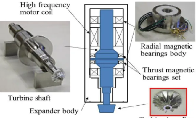
Recently, Turbo- Brayton refrigerators were developed in Japan and Europe [9-12]. Also, recent R&D efforts completed high efficient turbo-Brayton refrigerator as well as Stirling refrigerator [12]. It equips with magnetic bearings in rotational machines, namely, in turbo-compressor and turbo-expander. Fig. 9 shows a schematic drawing of a turbo-expander with magnetic bearings. There are two sets of magnetic radial bearings and one set of magnetic thrust bearings. Then, five axis- positions of a turbine shaft are controlled by those magnetic bearings. The rotational shaft can be levitated in a center of the radial bearings bodies and in a center of the thrust bearings air gap by magnetic force as shown Fig. 9. The air gap size between the shaft and the radial bearing body is set at around 0.5 mm. Magnetic bearings have no rubbing and consuming parts. The rotational machines are expected more than three years maintenance interval. That is very important matter for continuous operation of all year without break, especially HTS power electric application.
In Japan, neon gas is used as a working fluid. Neon gas has heavier molecular weight and is more effective to make high pressure ratio than Helium gas at the same rotational speed. In the other words, the compressor and expander can be operated at lower rotational speed by using neon gas, and it makes rotational machines more reliable.
For turbo-Brayton refrigerator, its maximum COP value is acquired at around 2 to 2.5 of pressure ratio with some heat exchanger efficiencies [13]. However, there is a border line at about 2 of pressure ratio for number of compression stages. In order to get more than 2 of pressure ratio, three-stage compression is needed, otherwise only two-stage compression is enough. Number of compression stages affects refrigerator cost. So, refrigerator makers are considering a balance of its COP and its cost.
Fig. 9. A schematic drawing of turbo-expander with magnetic bearings.
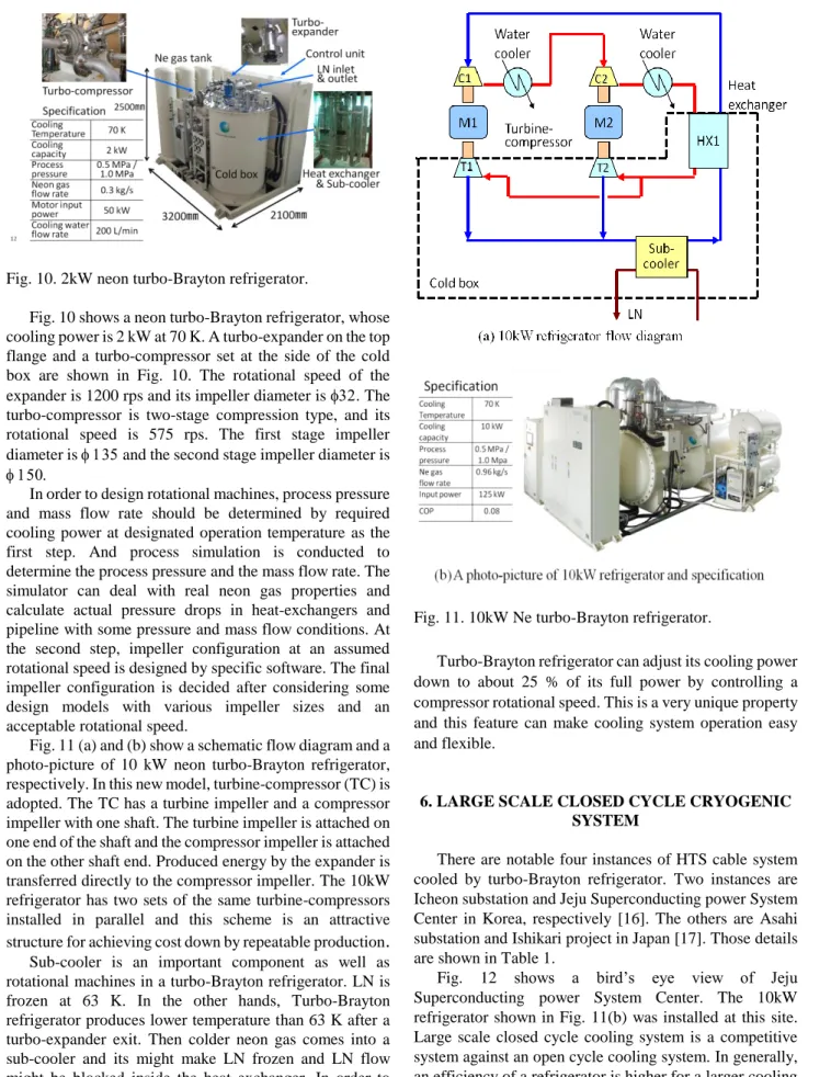
Fig. 10. 2kW neon turbo-Brayton refrigerator.
Fig. 10 shows a neon turbo-Brayton refrigerator, whose cooling power is 2 kW at 70 K. A turbo-expander on the top flange and a turbo-compressor set at the side of the cold box are shown in Fig. 10. The rotational speed of the expander is 1200 rps and its impeller diameter is . The turbo-compressor is two-stage compression type, and its rotational speed is 575 rps. The first stage impeller diameter is and the second stage impeller diameter is
In order to design rotational machines, process pressure and mass flow rate should be determined by required cooling power at designated operation temperature as the first step. And process simulation is conducted to determine the process pressure and the mass flow rate. The simulator can deal with real neon gas properties and calculate actual pressure drops in heat-exchangers and pipeline with some pressure and mass flow conditions. At the second step, impeller configuration at an assumed rotational speed is designed by specific software. The final impeller configuration is decided after considering some design models with various impeller sizes and an acceptable rotational speed.
Fig. 11 (a) and (b) show a schematic flow diagram and a photo-picture of 10 kW neon turbo-Brayton refrigerator, respectively. In this new model, turbine-compressor (TC) is adopted. The TC has a turbine impeller and a compressor impeller with one shaft. The turbine impeller is attached on one end of the shaft and the compressor impeller is attached on the other shaft end. Produced energy by the expander is transferred directly to the compressor impeller. The 10kW refrigerator has two sets of the same turbine-compressors installed in parallel and this scheme is an attractive structure for achieving cost down by repeatable production
.
Sub-cooler is an important component as well as rotational machines in a turbo-Brayton refrigerator. LN is frozen at 63 K. In the other hands, Turbo-Brayton refrigerator produces lower temperature than 63 K after a turbo-expander exit. Then colder neon gas comes into a sub-cooler and its might make LN frozen and LN flow might be blocked inside the heat exchanger. In order to prevent this undesired condition, some ideas are presented in literatures [14, 15]. One presented solution is a double loop heat exchanger and the other one is a cross flow heat exchanger.
Fig. 11. 10kW Ne turbo-Brayton refrigerator.
Turbo-Brayton refrigerator can adjust its cooling power down to about 25 % of its full power by controlling a compressor rotational speed. This is a very unique property and this feature can make cooling system operation easy and flexible.
6. LARGE SCALE CLOSED CYCLE CRYOGENIC SYSTEM
There are notable four instances of HTS cable system cooled by turbo-Brayton refrigerator. Two instances are Icheon substation and Jeju Superconducting power System Center in Korea, respectively [16]. The others are Asahi substation and Ishikari project in Japan [17]. Those details are shown in Table 1.
Fig. 12 shows a bird’s eye view of Jeju Superconducting power System Center. The 10kW refrigerator shown in Fig. 11(b) was installed at this site.
Large scale closed cycle cooling system is a competitive system against an open cycle cooling system. In generally, an efficiency of a refrigerator is higher for a larger cooling capacity refrigerator and operation cost per cooling power unit is reduced than smaller system. Large turbo-machine has a large diameter impeller and a leak flow rate through a
TABLE 1
HTS CABLE COOLING SYSTEM COOLED BY TURBO-BRAYTON REFRIGERATOR.
Site HTS cable
specification Cooling system
Icheon
AC 22.9kV 50MVA
410m
2kW TBR +
4kW Stiriling x 2 sets
Jeju
AC154kV 600MVA
1000m
10kWTBR + 4kW Stirling
Asahi
AC66kV 200MVA 240m
5kW TBR
Ishikari Line1
DC20kV 5kA 500m
2kW TBR + 1kW Stiriling Ishikari
Line2
DC20kV 2.5kA 1000m
2kW TBR x 2 sets +
1kW Stiriling x 2 sets *)TBR:Turbo-Brayton Refrigerator
Fig. 12. Jeju island HTS cable field test.
gap between impeller and its casing is relatively small. This is the main reason for getting higher efficiency.
Furthermore, a large refrigerator has a lower price for cooling power unit, namely, a price for 1 kW cooling power.
First capital investment for large scale cryogenic cooling system is still expensive, but its moderate operation cost is more attractive against open cycle cryogenic cooling system. Its border could be at around 10 kW cooling power.
7. REFRIGERATOR EFFICIENCY IMPROVEMENT
It is important to know that a refrigeration process analysis contributes to the efficiency of the refrigeration as well as turbo-machine efficiency. The basic turbo Brayton is generating pressure by adiabatic compression and input power to get desired compression ratio can be reduced by multi-stage compression method. Multi-stage compression can make compression process similar to isothermal compression process. However, adopting a multi-stage process, the number of compression stages should be a considerable item which might be disadvantaged in terms
Fig. 13. Cold compression process flow diagram.
of high cost and trouble prevention. For expansion process, multi-stage expansion can generate more energy as similar as a multi-stage turbo-compressor merit. Provided, that the efficiency improvement by multi-stage turbo-expander is possible, we must consider the overall cost performance as well as the adoption of multi-stage compressor.
In addition, from the viewpoint of power saving, compression process at low temperature (cold compression process) should be also considered. Adiabatic compression work energy is theoretically proportional to its temperature.
When cold compression process is working at 150 K, the required work is reduced to be half by compression work at 300 K. Freon refrigerator can be used as a pre-cooler in addition to the basic Brayton cycle, and also cold LNG mass can be put into a cold compression process as shown in Fig. 13.
In case of LNG utilization, compressor must be working at around 150 K. This situation is very severe circumstance for compressor, and there are some technical issues to break through. However, low temperature compression technique is very effective for improving refrigerator efficiency, and development and performance enhancement of turbo compressor in cold temperature is an attractive research and development target.
8. CONCLUSION
Brayton cycle is a historical heat engine theory but actual turbo-Brayton refrigerator is an unmatured technology. Application for HTS equipment cooling system is just begun recently. COP of turbo-Brayton refrigerator is now reaching at nearby 0.1 and it is expected to be more than 0.1. Turbo-Brayton refrigerator has large potential of developing high efficient and maintenance-free machine.
As described above, turbo-Brayton refrigerator performance is going up day by day. However, LN circulation pump performance improvement is not sufficient. LN circulation pump is one of the most important machines which make up cryogenic system for HTS power application. Present LN pump has a short
maintenance interval, which is less than one year. LN pump is also expected as a maintenance-free machine.
Cryogenic system is an essential element for HTS application system, but it is far from a leading role in this region. Cryogenic system is required the following features; easy operation, high reliability, strong durability, reliable safety, high efficiency, moderate cost, etc., But, as the first of all, cryogenic system should be invisible to spread superconducting power equipment. It means that the feeling of its presence should be disappeared. The best thing is that HTS power application operator doesn’t know the existence of cryogenic system.
For operation of the HTS application system, cryogenic system should not be required expertise and should be needed only an easy handling. Then, it will be indispensable that any operation modes including cool down are automatically controlled. Fault diagnosis and emergency measures by experts are sometimes inevitable.
Therefore, it is a matter of rapid to equip emergency measures using remote monitoring and remote control functions.
Government regulation is also a related matter to spreading HTS power application. In some countries, cryogenic system is regulated by high pressure gas safety law or such kind legislation. Those regulations are sometimes conflictive with for desired unattended operation of HTS power application equipment.
Unattended operation is very usual at electricity distributing substations in Korea and Japan. In Japan, deregulation is being promoted by academic and industrial societies. On promoting such deregulation, the most important thing is a showing evidence of systematic safety to authorities by accumulating safety operation data.
In order to spread HTS power application rapidly, very intimate relationship with superconducting equipment specialists and cooling system specialists is indispensable, and aggressive collaboration between them from the design stage of new superconducting equipment is also needed.
Furthermore, electric and mechanical system experts should be joined in the group. It is believed that Generous and ceaseless efforts by many researchers and engineers can realize superconducting world.
REFERENCES
[1] J. Suehiro, M. Hara, H. Izawa, K. Funaki, N. Tamuro and M.
Iwakuma, “Effects of Thermal Bubbles and Pressure on Partial Discharge Characteristics in Composite Insulation System of Liquid Nitrogen and Solid Insulator,” IEEJ Transaction on Fundamental and Material, vol.119, issue.3, pp.299-304, 1999.
[2] M. Hara and M. Kubuki, “Effect of thermally induced bubbles on the electrical breakdown characteristics of liquid nitrogen,” IEE Proceedings A - Physical Science, Measurement and Instrumentation, Management and Education,” vol. 137, issue 4, pp.
209 – 216, 1990.
[3] S. Yoshida, Y.Yagi, T. Umeno, T. Ishida, Y. Kamioka, H. Ogino, M.
Iwakuma, K. Funaki, Y. Yasukawa and M. Konno, “1ATM Subcooled Liquid Nitrogen Cryogenic System for Oxide Superconducting Power Transformer”, Advances in Cryogenic Engineering, vol. 43, pp. 1191-1198, 1998.
[4] K. Nishikawa and Y. Fujita, Heat Transfer in Japanese, Tokyo, Rikougaku Sya, 1993, pp. 231.
[5] R. Barron, Cryogenic Systems Second Edition, New York, Oxford university press, 1985, pp. 114-115.
[6] M. Yagi; J. Liu; S. Mukoyama; T. Mitsuhashi; J. Teng, N.
Hayakawa; X. Wang; A. Ishiyama; N. Amemiya; T.Hasegawa; T.
Saitoh, O. Maruyama and T. Ohkuma, “Experimental Results of 275-kV 3-kA REBCO HTS Power Cable,” IEEE Transactions on Applied Superconductivity, vol. 25, no. 3, pp. 5401405., 2015.
[7] H. Yang, S. Sohn, J. Lim, S. Yim, H. Jeon, S. Jung, S. Han and S.
Hwang, “Decompression Cooling System Operation for HTS Power Cable in the KEPCO Power Grid,” Advances in Cryogenic Engineering, vol. 59B, pp.1678-1684, 2014.
[8] F. Herzog, T. Kutz, M. Stemmle and T. Kugel, “Cooling unit for the AmpaCity Project – one year successful operation,” Cryogenics, vol.
80, part 2, pp.204-209, 2016.
[9] S. Yoshida, H. Hirai, N. Nara, S. Ozaki, M. Hirokawa, T. Eguchi, H.
Hatashi, M. Iwakuma and Y. Shiohara, “Sub-cooled liquid nitrogen cryogenic system with neon turbo-refrigerator for HTS power equipment,” Advances in Cryogenic Engineering, vol. 59B, pp.1246-1253, 2014.
[10] H. Hirai, .Hirokawa, S. Yoshida, T. Sano and S. Ozaki,
“Development of a turbine-compressor for 10 kW class neon turbo-Brayton refrigerator,” Advances in Cryogenic Engineering, vol. 59B, pp.1236-1241, 2014.
[11] Air Liquid home page,
https://advancedtech.airliquide.com/turbo-brayton-cryogenic-syste ms.
[12] Matekawa MFG Co., Ltd., “Brayton cycle crycooler Brayton NeO,”
leaflet, October 2015
[13] S. Yoshida, H. Hirai, A. Takaike, M. Hirokawa, Y. Aizawa, Y.
Kamioka, H. Okamoto, H. Hayashi and Y. Shiohara, “New design of neon refrigerator for HTS power machines,” Advances in Cryogenic Engineering, vol. 55, pp.1131-1138, 2010.
[14] S. Yoshida, H. Hirai, N. Nara, T. Nagasaka, M. Hirokawa, H.
Okamoto, H. Hayashi and Y. Shiohara, “Consideration of sub-cooled LN2 circulation system for HTS power equipment,” Advances in Cryogenic Engineering, vol. 57, pp. 1649-1656, 2012.
[15] H. Chang, K. Gwak, H. Yang and S. Hwang, “Cross-flow heat exchangers for anti-freezing of liquid nitrogen,” Cryogenics, vol. 57, pp.122–128, 2013.
[16] S. Hwang, “Real grid operation of HTS cables installed in KEPCO grid”, IEA ExCo meeting at Munich, Germany, May 2016.
[17] K. Sato, “Overview of HTS Large Scale Application in Japan (Plenary presentation AT-2 given at 1st Asian ICMC – CSSJ 50thAnniversary Conference; Kanazawa),” IEEE/CSC & ESAS superconductivity news forum (global edition), January 2017.
![Fig. 2 shows a historical open cycle cooling system made in 1996, and its cooling power is only 100 watt [3]](https://thumb-ap.123doks.com/thumbv2/123dokinfo/5237371.623967/2.892.459.807.136.342/fig-shows-historical-open-cycle-cooling-cooling-power.webp)