• 검색 결과가 없습니다.

Reliability of cone-beam computed tomography for temporomandibular joint analysis

N/A
N/A
Protected

Academic year: 2022

Share "Reliability of cone-beam computed tomography for temporomandibular joint analysis"

Copied!
8
0
0

로드 중.... (전체 텍스트 보기)

전체 글

(1)

Reliability of cone-beam computed tomography for temporomandibular joint analysis

Objective: The aim was to assess the intraobserver and interobserver reliabilities of temporomandibular joint linear measurements and condylar shape classifi- cations performed with cone-beam computed tomography (CBCT). Methods:

CBCT images of 30 patients were measured at two different time points by two orthodontists using the Dolphin 3D program (n = 60). Anterior, posterior, and superior joint space measurements and sagittal joint morphology classification in the sagittal view and medial and lateral joint space and mediolateral width mea- surements and coronal joint morphology classification in the coronal view were recorded. Intraclass-interclass correlation coefficients (ICC) and kappa statistics were used to assess intraobserver and interobserver reliability for the measure- ments and morphology classifications, respectively. Results: The ICC values were good for measurements of the posterior joint space by observer I and for mea- surements of the posterior, medial, and lateral joint spaces by observer II, while the other intraobserver measurements were excellent. Only the mediolateral width measurements showed excellent interobserver ICC values, while the other mea- surements showed good interobserver ICC values. Intraobserver agreement for the sagittal morphology classifications was moderate (k = 0.479) and almost perfect (k

= 0.858) for observers I and II, respectively, while the corresponding agreement for the coronal morphology classifications was substantial for both observers.

The interobserver agreement values for sagittal and coronal morphology clas- sifications were slight (k = 0.181) and fair (k = 0.265), respectively. Conclusions:

Linear temporomandibular joint measurements were reproducible and reliable in both intraobserver and interobserver evaluations. However, interobserver agree- ment for assessments of condylar shape was low.

[Korean J Orthod 2019;49(2):81-88]

Key words: Temporomandibular joint measurement, Condyle shape, Reliability, Cone-beam computed tomography

Hande Gorucu-Coskuner Ezgi Atik

Hakan El

Department of Orthodontics, School of Dentistry, Hacettepe University, Ankara, Turkey

Received March 29, 2018; Revised May 14, 2018; Accepted June 22, 2018.

Corresponding author: Hande Gorucu-Coskuner.

Assistant Professor, Department of Orthodontics, School of Dentistry, Hacettepe University, Sıhhıye, 6100 Ankara, Turkey.

Tel +90-312-305-22-90 e-mail [email protected]

How to cite this article: Gorucu-Coskuner H, Atik E, El H. Reliability of cone-beam computed tomography for temporomandibular joint analysis. Korean J Orthod 2019;49:81-88.

© 2019 The Korean Association of Orthodontists.

This is an Open Access article distributed under the terms of the Creative Commons Attribution Non-Commercial License (http://creativecommons.org/licenses/by-nc/4.0) which permits unrestricted non-commercial use, distribution, and reproduction in any medium, provided the original work is properly cited.

pISSN 2234-7518 • eISSN 2005-372X

https://doi.org/10.4041/kjod.2019.49.2.81

(2)

INTRODUCTION

Condylar position and morphology are important fea- tures that are mostly underestimated and should be tak- en into account during orthodontic treatment planning.

Considering the importance of harmony between the dentition and the associated musculoskeletal structures in ensuring stability of the occlusion, temporomandibu- lar joint (TMJ)-oriented treatment planning has gained popularity recently.

1

The condylar position has been suggested to be an important factor in providing or re- establishing temporomandibular harmony with the den- tition and is important for achieving a stable occlusion after orthodontic treatment.

2

Therefore, orthodontists should not only correct tooth alignment and occlusal interferences, but also create harmonious condylar posi- tions with respect to the dentition.

3

The TMJ has a complex anatomy composed of the mandibular condyle, temporal bone, and articular disk.

Additionally, the TMJ is surrounded by bony structures.

Because of these characteristics, the TMJ cannot be easily visualized with traditional 2-dimensional radiog- raphy. For 3-dimensional (3D) evaluation of the TMJ, computed tomography (CT) and magnetic resonance imaging (MRI) have been suggested previously.

4,5

MRI is commonly used for assessment of soft tissue structures, whereas CT is used to assess the osseous components of the TMJ.

6

Cone-beam computed tomography (CBCT) can overcome the limitations of conventional CT, such as high cost, difficulties in access to equipment, and relatively high radiation dose.

6

However, CBCT has lim- ited low-contrast resolution due to various physical and technical factors, which can limit its usefulness in soft tissue evaluations.

7

The highly scattered radiation dur- ing image acquisition adversely affects the contrast in the projection data and the final reconstructed images.

8

Despite these limitations, CBCT has become a highly preferred imaging modality for evaluation of the osseous structures of the TMJ.

3,9-11

One of the main advantages of CBCT is its ability to produce scans with varying fields of view (FOVs).

Therefore, direct scans from the required region can be obtained according to the clinical indication.

8

Although CBCT with a large FOV has limited utility in most condi- tions, the American Academy of Oral and Maxillofacial Radiology suggests that image acquisition with a medi- um-sized or large FOV can be indicated for evaluation of anteroposterior, vertical and transverse discrepancies, asymmetries, and signs and symptoms of temporoman- dibular disorder (TMD).

12

The goals of TMJ imaging by CBCT are to assess the integrity of the bony structures in case of disorders, verify the extent and stage of the disorders, and evalu- ate the effects of treatment.

6

The condylar positions and

shapes in different malocclusions

3,9,11,13-15

and the ef- fects of orthodontic treatment on condylar positions

10,16

have recently become topics of interest. Although sev- eral studies have dealt with the aforementioned top- ics,

3,9-11,13-16

to our knowledge, there is no study solely evaluating the reliability of TMJ space measurements and condylar shape classifications performed using CBCT. Therefore, the null hypothesis of this study was that TMJ linear measurements and condylar shape clas- sifications obtained using CBCT with sagittal and coro- nal sections are reliable in intraobserver and interob- server evaluations.

MATERIALS AND METHODS

Ethical approval for this investigation was granted by Hacettepe University Ethical Committee (approval number, GO 16/591-23). CBCT images of 30 patients were selected from the digital archives of Department of Orthodontics, School of Dentistry, Hacettepe Uni- versity. These images were taken from the patients for presurgical evaluation and no other extra radiologic examinations were performed. CBCT scans were selected irrespective of the patients’ sex by applying the follow- ing inclusion criteria: (1) no history of TMDs, (2) no sys- temic diseases that could affect TMJ, (3) no congenital diseases or syndromes, (4) CBCT scans taken with i-CAT Cone Beam 3D Imaging System (Imaging Sciences Inter- national, Hatfield, PA, USA) at maximum intercuspation, (5) both right and left condyles fully contained in the images, and (6) no deficient image quality or artifacts.

The selected subjects’ ages ranged between 15 and 22 years. The subjects were in an upright sitting position with the Frankfurt horizontal plane parallel to the floor.

The scanning settings for the CBCT machine were as follows: FOV, 23 × 17 cm (voxel size, 0.30 mm); tube voltage, 120 kVp; tube current, 2 mA; and scan time, 17.8 seconds. CBCT data were exported in the Digital Imaging and Communications in Medicine (DICOM) for- mat.

Before obtaining the measurements, two orthodontists

with 9 years’ experience (HGC and EA) were trained to

perform TMJ linear measurements and condyle shape

classifications using the teaching material from Dalili et

al.

13

and Kinzinger et al.

17

The training included a de-

tailed explanation of the hand-drawn illustrations and

a calibration exercise conducted at the beginning of the

study. The calibration protocol included an explanation

of the 3D measurement tools in the Dolphin Imaging

software and a demonstration of the measurements to

be made for this research. To allow blinded assessments,

the images were randomly analyzed and the examiners

did not have access to their previous measurements in

the second analysis.

(3)

The images were exported to the Dolphin 3D pro- gram (version 11.8; Dolphin Imaging & Management Solutions, Chatsworth, GA, USA) for the measurements.

Initially, all radiographs were oriented in the coronal, sagittal, and axial planes for standardization. The sagit- tal plane was adjusted to reflect the midsagittal plane as bisecting symmetric midfacial structures. The axial plane was constructed as a line passing through the most superior point of the meatus acusticus externus and the most inferior point of the orbital rim on the right and left sides, to reflect the Frankfurt horizontal plane.

Finally, the coronal plane was adjusted by using the transporionic line. After the orientation, all radiographs were saved; subsequently, the two observers performed the following procedures separately for all measure- ments and classifications.

The center and the long axes of the condyles were selected from the sagittal and axial views to create the TMJ images. The axial slice thickness was set to 1 mm and circular direction settings were applied in order to identify the largest and most pronounced condyle image for the right and left joints separately (Figure 1). After creation of the TMJ images, coronal and sagittal mea- surements were performed from 90

o

to 270

o

and 0

o

to 180

o

perspectives, respectively. The following measure- ments for right and left joints were performed twice by two calibrated orthodontists within 15-day intervals (n = 60).

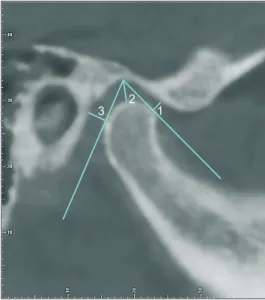
From the sagittal view (Figure 2);

1. Anterior joint space (AJS): The line tangential to the anterior aspect of the condyle was drawn from the most superior point of the glenoid fossa. The perpendicular distance from the anterior tangential plane to the glenoid fossa was measured as the

AJS.

2. Superior joint space (SJS): The distance from the most superior point of the glenoid fossa to the most superior aspect of the condyle was measured as the SJS.

3. Posterior joint space (PJS): The line tangential to the posterior aspect of the condyle was drawn from the most superior point of the glenoid fossa. The perpendicular distance from the posterior tangen- tial plane to the glenoid fossa was measured as the PJS.

4. Sagittal condyle morphology classification: The sagittal condyle morphology was classified as (A) rounded, (B) anteriorly flattened, or (C) posteriorly flattened, in accordance with the recommendations by Kinzinger et al.

17

From the coronal view (Figure 3);

1. Medial joint space (MJS): A tangent line was drawn from the deepest point to the medial slope of the glenoid fossa. The perpendicular line from the most prominent point of the medial pole of the condyle to the tangent line was measured as the MJS.

2. Lateral joint space (LJS): A tangent line was drawn from the deepest point to the lateral slope of the glenoid fossa. The perpendicular line from the most prominent point of the lateral pole of the condyle to the tangent line was measured as the LJS.

3. Mediolateral width (MLW): The distance from the most prominent point of the medial pole to the most prominent point of the lateral pole was mea- sured as the MLW.

4. Coronal condyle morphology classification: The coronal condyle morphology was classified as (A) round, (B) convex, or (C) angulated, in accordance

Figure 1. Arrangement of the left condyle’s long axis.

3 2

1

Figure 2. Measurement of the anterior (1), superior (2),

and posterior (3) joint spaces.

(4)

with the scheme outlined by Kinzinger et al.

17

The data were analyzed using IBM SPSS Statistics version 21.0 (IBM Corp., Armonk, NY, USA). Using intraclass-interclass correlation coefficients (ICC) with 95% confidence intervals, intraobserver reliability was assessed as the agreement between the first and second measurements by each observer (HGC, EA) and interob- server reliability was assessed as the agreement between the first measurements by both observers. ICC values were classified in accordance with the study by Mattos et al.

18

as follows: excellent, above 0.9; good, between 0.75 and 0.9; moderate, between 0.5 and 0.75; and poor, below 0.5. The intraobserver and interobserver reli- abilities of the morphology classifications were evaluated with kappa statistics. Kappa values were categorized in accordance with the study by Landis and Koch

19

as fol- lows: almost perfect, above 0.8; substantial, between 0.6 and 0.8; moderate, between 0.4 and 0.6; fair, between

0.2 and 0.4; and slight, between 0 and 0.2.

RESULTS

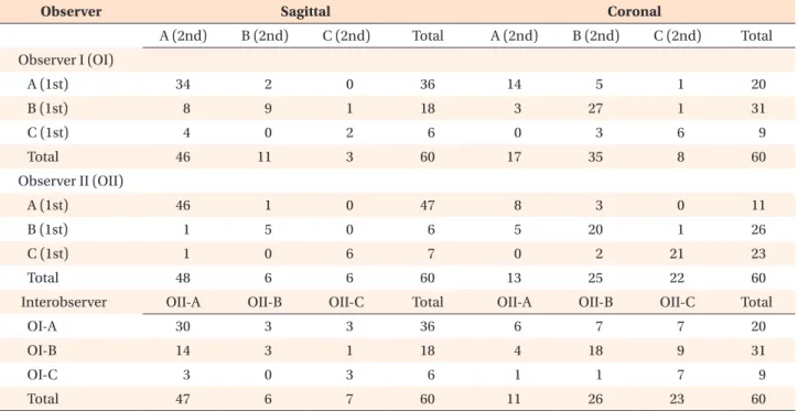
The ICC values for the measurements (AJS, SJS, PJS, MJS, LJS, and MLW) are shown in Table 1. The AJS, SJS, MJS, LJS, and MLW measurements by observer I and the AJS, SJS, and MLW measurements by observer II showed excellent ICC values (> 0.9). The PJS measurement by observer I and the PJS, MJS, and LJS measurements by observer II showed good ICC values (between 0.75 and 0.9). The only excellent interobserver ICC value (> 0.9) was obtained for the MLW measurement, while the re- maining values were in the good range (between 0.75 and 0.9).

The sagittal and coronal morphology classifications by the observers and the intraobserver/interobserver com- parisons are shown in Table 2. The kappa values

19

for intraobserver and interobserver agreements are shown in Table 3. In evaluations of the morphological clas- sifications, observer I showed moderate (k = 0.479) and substantial (k = 0.629) intraobserver agreement for the sagittal and coronal classifications, respectively. Observer II showed almost perfect (k = 0.858) and substantial (k

= 0.713) intraobserver agreement for the sagittal and coronal classifications, respectively. The interobserver agreement values were slight (k = 0.181) and fair (k = 0.265) for the sagittal and coronal classifications, re- spectively.

DISCUSSION

Appropriate evaluation of the TMJ is vital for accurate diagnosis and treatment planning before orthodontic treatment. Therefore, consistency across TMJ evalua- tions performed by different clinicians is an essential criterion for any evaluation technique. Considering these factors, the null hypothesis of this study was that TMJ linear measurements and condylar shape classifications performed using CBCT are reliable.

Table 1. Analysis of the anterior, superior, posterior, medial, and lateral joint space and mediolateral width measurements

Variable Observer I Observer II*** Interobserver***

ICC 95% CI ICC 95% CI ICC 95% CI

Anterior joint space 0.914 0.856–0.949 0.924 0.873–0.955 0.899 0.832–0.940

Superior joint space 0.931 0.885–0.959 0.915 0.858–0.949 0.856 0.759–0.914

Posterior joint space 0.894 0.823–0.937 0.895 0.824–0.937 0.848 0.746–0.909

Medial joint space 0.917 0.862–0.951 0.815 0.690–0.889 0.891 0.818–0.935

Lateral joint space 0.904 0.840–0.943 0.897 0.828–0.939 0.853 0.753–0.912

Mediolateral width 0.992 0.986–0.995 0.975 0.957–0.985 0.993 0.988–0.996

ICC, Intraclass-interclass correlation coefficient; 95% CI, 95% confidence interval.

***p < 0.001.

Figure 3. Measurement of the medial (1) and lateral (2) joint spaces and the mediolateral width (3).

3 1 2

(5)

CBCT has recently gained popularity for evaluation of condylar positions

3,9-11,13,15,20,21

and morphologies,

9,17

be- cause of the high-quality images and superior anatomic presentation with lower radiation doses in comparison with conventional CT.

22

However, TMJ measurements are mostly performed in two dimensions and CBCT im- ages are not as widely used even though a novel semi- automatic method has recently been introduced for 3D analysis of the TMJ.

23

At this point, the main aim of 3D imaging is to choose the correct section of the TMJ for measurements. However, in studies involving the relationship between the condyle and glenoid fossa, it is difficult to make a reliable deduction in a 3D view due to the complex anatomy of the region. Therefore,

researchers prefer to measure the anterior, posterior, and SJSs along with morphological evaluations on a selected 2D view of interest.

As the measurements are performed on one slice, the selection of an appropriate slice is extremely important.

This selection is even more important when condyle po- sitions are evaluated for treatment planning and treat- ment outcomes. Using 3D images, the most accurate and repeatable slice should be selected for measurements.

The axial view revealing the widest mediolateral diam- eter of the condyle is usually preferred for determina- tion of the long axis of the condyle and creation of the sagittal and coronal views used for measurements.

11,13,20

However, Park et al.

3

selected the slices from the sagit- Table 2. Intraobserver and interobserver comparisons of sagittal and coronal morphology classifications

Observer Sagittal Coronal

A (2nd) B (2nd) C (2nd) Total A (2nd) B (2nd) C (2nd) Total

Observer I (OI)

A (1st) 34 2 0 36 14 5 1 20

B (1st) 8 9 1 18 3 27 1 31

C (1st) 4 0 2 6 0 3 6 9

Total 46 11 3 60 17 35 8 60

Observer II (OII)

A (1st) 46 1 0 47 8 3 0 11

B (1st) 1 5 0 6 5 20 1 26

C (1st) 1 0 6 7 0 2 21 23

Total 48 6 6 60 13 25 22 60

 Interobserver OII-A OII-B OII-C Total OII-A OII-B OII-C Total

OI-A 30 3 3 36 6 7 7 20

OI-B 14 3 1 18 4 18 9 31

OI-C 3 0 3 6 1 1 7 9

Total 47 6 7 60 11 26 23 60

1st, First measurements; 2nd, second measurements.

The sagittal condyle morphology was classified as (A) rounded, (B) anteriorly flattened, or (C) posteriorly flattened. The coronal condyle morphology was classified as (A) round, (B) convex, or (C) angulated.

Table 3. Analysis of intraobserver and interobserver agreement for the sagittal and coronal morphology classifications

Agreement (%) k SE Significance

Observer I-sagittal 75 0.479 0.106 < 0.001***

Observer II-sagittal 95 0.858 0.08 < 0.001***

Observer I-coronal 78 0.629 0.091 < 0.001***

Observer II-coronal 82 0.713 0.077 < 0.001***

Interobserver-sagittal 60 0.181 0.109 0.038*

Interobserver-coronal 52 0.265 0.089 0.002**

SE, Standard error.

*p < 0.05; **p < 0.01; ***p < 0.001.

(6)

tal view with the criterion, “a clear view of the condyle and mandibular fossa with a clear continuous line of cortical bone.” Nevertheless, the authors think that the aforementioned selection of a “clear view” could lead to further disagreements between the operators. Thus, in the present study, the axial view with the largest and most pronounced condyle was selected separately for the right and left joints to create the sagittal and coro- nal views and increase repeatability.

In the present study, the Dolphin 3D program was used for measurements. Since the program has a special tool for TMJ measurements, it allows aspects of the TMJ at different angles to be viewed easily. From the sagit- tal section, anterior, superior, and PJSs were measured.

The literature contains details for several measurement techniques using the same software. Most of these stud- ies

3,9,11,24-26

measured the anterior, superior, and PJSs as the nearest point from the glenoid fossa to the anterior, superior, and posterior points of the condyle, respective- ly. In addition, some authors

13,16,21,27

described tangents drawn from the most superior point of the fossa to the most prominent anterior and posterior points of the condyles for determination of the points. As the “closest distance” can be measured from different points and is more prone to miscalculations, the tangents were used for determination of the most prominent points of the joints in the present study. Similarly, for measurement of the medial and LJSs, the tangents were drawn from the deepest point to the medial and lateral slopes of the glenoid fossa, and the perpendicular line from the poles to the tangent line was measured.

13

The findings of the present study indicate that the reliability of measurements of the anterior, superior, posterior, medial, and LJSs and the MLW varies between good and excellent. Although this might imply that linear TMJ measurements are reproducible and reliable, further studies should be conducted to assess the accu- racy of the measurements. For both observers, measure- ments of the anterior and SJSs and the MLW showed excellent reliability and that of the PJS showed good reliability. Thus, linear measurements of the condyles can be considered reliable and reproducible. Similar to our findings, Park et al.

3

and Paknahad et al.

11

found intraclass correlations above 0.9 and high intraobserver reliability in their studies related to TMJ evaluations.

The morphological classifications were performed in accordance with the study by Kinzinger et al.

17

Although several studies have evaluated the condylar morphol- ogy,

9,14,17

to our knowledge, no study has attempted to assess the reliability of condylar morphology classifica- tion. Although the intraobserver agreement for observer I was moderate and substantial for sagittal and coronal classifications, respectively, the corresponding values for observer II were almost perfect and substantial, re-

spectively. This might indicate that sagittal morphology classification is operator-dependent. However, as the interobserver agreement values for sagittal and coronal classifications were slight, CBCT imaging may not be suitable for classification of condylar shapes. Although transcranial or anteroposterior transmaxillary radiographs allow direct measurement without attempting to find any cross-sectional slices, it is important to also evaluate the 3D anatomy of the joint complex.

The changes in the shape of the condyle might be at- tributable to disc displacement.

28,29

Therefore, clinicians should consider any abnormal morphological changes, since there may be a correlation between the disc posi- tion and the morphology of the condyle. In the present study, the condylar morphology classifications were per- formed by two orthodontists who underwent a calibra- tion exercise with hand-drawn illustrations. However, the morphologies seen in the CBCT images are not as clear as those observed in the illustrations. Moreover, each orthodontist separately selected the CBCT slice in which the morphology classification was done. These factors may have contributed to the low agreement percentages. To overcome these issues, clinicians should consider evaluating consecutive slices of the condyle for morphology classification.

In the present study, the intraobserver agreement was higher than the interobserver agreement, as expected.

Different factors such as background experiences, ob- server familiarity with the software, and the ability to identify landmarks according to the definitions can af- fect observer performance.

30

To minimize these factors, two observers with similar experience levels were select- ed from the same clinic and were calibrated before they performed observations.

Although the study had some limitations such as the insufficient number of observers and use of only one program, to our knowledge, this is the first study to evaluate the interobserver and intraobserver reliabilities for linear TMJ measurements and morphology classifi- cations, and further studies are needed to improve our findings.

CONCLUSION

The findings demonstrate that 2-dimensional linear

TMJ measurements in the coronal and sagittal views on

CBCT images were reproducible and reliable. However,

the use of CBCT imaging for classification of condylar

shapes in the coronal and sagittal views may not provide

clinically useful information, as the interobserver agree-

ment values for these classifications were low and the

intraobserver agreement was mostly operator-dependent.

(7)

CONFLICTS OF INTEREST

No potential conflict of interest relevant to this article was reported.

REFERENCES

1. Okeson JP. Orthodontic therapy and the patient with temporomandibular disorder. In: Graber LW, Vanarsdall RL, Vig KWL, Huang GJ, eds. Orthodon- tics: current principles and techniques. 6th ed. St.

Louis, Missouri: Elsevier; 2017. p. 353-66.

2. Kaur A, Natt AS, Mehra SK, Maheshwari K, Singh G, Kaur A. Improved visualization and assessment of condylar position in the glenoid fossa for different occlusions: a CBCT study. J Contemp Dent Pract 2016;17:679-86.

3. Park IY, Kim JH, Park YH. Three-dimensional cone- beam computed tomography based comparison of condylar position and morphology according to the vertical skeletal pattern. Korean J Orthod 2015;45:

66-73.

4. Al-Saleh MA, Alsufyani NA, Saltaji H, Jaremko JL, Major PW. MRI and CBCT image registration of temporomandibular joint: a systematic review. J Otolaryngol Head Neck Surg 2016;45:30.

5. Brooks SL, Brand JW, Gibbs SJ, Hollender L, Lurie AG, Omnell KA, et al. Imaging of the temporo- mandibular joint: a position paper of the Ameri- can Academy of Oral and Maxillofacial Radiology.

Oral Surg Oral Med Oral Pathol Oral Radiol Endod 1997;83:609-18.

6. Barghan S, Tetradis S, Mallya S. Application of cone beam computed tomography for assessment of the temporomandibular joints. Aust Dent J 2012;57 Suppl 1:109-18.

7. Adibi S, Zhang W, Servos T, O'Neill PN. Cone beam computed tomography in dentistry: what dental educators and learners should know. J Dent Educ 2012;76:1437-42.

8. Kiljunen T, Kaasalainen T, Suomalainen A, Kortesni- emi M. Dental cone beam CT: A review. Phys Med 2015;31:844-60.

9. Merigue LF, Conti AC, Oltramari-Navarro PV, Na- varro Rde L, Almeida MR. Tomographic evaluation of the temporomandibular joint in malocclusion subjects: condylar morphology and position. Braz Oral Res 2016;30:S1806-83242016000100222. doi:

10.1590/1807-3107BOR-2016.vol30.0017.

10. Coskuner HG, Ciger S. Three-dimensional assessment of the temporomandibular joint and mandibular di- mensions after early correction of the maxillary arch form in patients with Class II division 1 or division 2 malocclusion. Korean J Orthod 2015;45:121-9.

11. Paknahad M, Shahidi S, Abbaszade H. Correlation between condylar position and different sagittal skeletal facial types. J Orofac Orthop 2016;77:350- 6.

12. American Academy of Oral and Maxillofacial Radiol- ogy. Clinical recommendations regarding use of cone beam computed tomography in orthodontics. [cor- rected]. Position statement by the American Acad- emy of Oral and Maxillofacial Radiology. Oral Surg Oral Med Oral Pathol Oral Radiol 2013;116:238-57.

13. Dalili Z, Khaki N, Kia SJ, Salamat F. Assessing joint space and condylar position in the people with normal function of temporomandibular joint with cone-beam computed tomography. Dent Res J (Isfa- han) 2012;9:607-12.

14. Katsavrias EG. Morphology of the temporomandibu- lar joint in subjects with Class II Division 2 maloc- clusions. Am J Orthod Dentofacial Orthop 2006;129:

470-8.

15. Martins E, Silva JC, Pires CA, Ponces-Ramalhão MJ, Lopes JD. Coronal joint spaces of the temporoman- dibular joint: Systematic review and meta-analysis. J Clin Exp Dent 2015;7:e435-40.

16. Leonardi R, Caltabiano M, Cavallini C, Sicurezza E, Barbato E, Spampinato C, et al. Condyle fossa rela- tionship associated with functional posterior cross- bite, before and after rapid maxillary expansion.

Angle Orthod 2012;82:1040-6.

17. Kinzinger G, Kober C, Diedrich P. Topography and morphology of the mandibular condyle during fixed functional orthopedic treatment --a magnetic reso- nance imaging study. J Orofac Orthop 2007;68:124- 47.

18. Mattos CT, Cruz CV, da Matta TC, Pereira Lde A, Solon-de-Mello Pde A, Ruellas AC, et al. Reliability of upper airway linear, area, and volumetric mea- surements in cone-beam computed tomography. Am J Orthod Dentofacial Orthop 2014;145:188-97.

19. Landis JR, Koch GG. The measurement of ob- server agreement for categorical data. Biometrics 1977;33:159-74.

20. Paknahad M, Shahidi S, Iranpour S, Mirhadi S, Pak- nahad M. Cone-beam computed tomographic as- sessment of mandibular condylar position in patients with temporomandibular joint dysfunction and in healthy subjects. Int J Dent 2015;2015:301796.

21. Imanimoghaddam M, Madani AS, Mahdavi P, Bagh- erpour A, Darijani M, Ebrahimnejad H. Evaluation of condylar positions in patients with temporomandib- ular disorders: a cone-beam computed tomographic study. Imaging Sci Dent 2016;46:127-31.

22. Honey OB, Scarfe WC, Hilgers MJ, Klueber K, Silveira

AM, Haskell BS, et al. Accuracy of cone-beam com-

puted tomography imaging of the temporoman-

(8)

dibular joint: comparisons with panoramic radiology and linear tomography. Am J Orthod Dentofacial Orthop 2007;132:429-38.

23. Ikeda R, Oberoi S, Wiley DF, Woodhouse C, Tallman M, Tun WW, et al. Novel 3-dimensional analysis to evaluate temporomandibular joint space and shape.

Am J Orthod Dentofacial Orthop 2016;149:416-28.

24. Vitral RW, Telles Cde S, Fraga MR, de Oliveira RS, Tanaka OM. Computed tomography evaluation of temporomandibular joint alterations in patients with Class II division 1 subdivision malocclusions:

condyle-fossa relationship. Am J Orthod Dentofacial Orthop 2004;126:48-52.

25. Rodrigues AF, Fraga MR, Vitral RW. Computed to- mography evaluation of the temporomandibular joint in Class I malocclusion patients: condylar sym- metry and condyle-fossa relationship. Am J Orthod Dentofacial Orthop 2009;136:192-8.

26. Rodrigues AF, Fraga MR, Vitral RW. Computed to- mography evaluation of the temporomandibular joint in Class II Division 1 and Class III malocclu-

sion patients: condylar symmetry and condyle- fossa relationship. Am J Orthod Dentofacial Orthop 2009;136:199-206.

27. Ikeda K, Kawamura A. Assessment of optimal con- dylar position with limited cone-beam computed tomography. Am J Orthod Dentofacial Orthop 2009;135:495-501.

28. Cholasueksa P, Warita H, Soma K. Alterations of the rat temporomandibular joint in functional posterior displacement of the mandible. Angle Orthod 2004;

74:677-83.

29. Isacsson G, Isberg A, Johansson AS, Larson O. Inter- nal derangement of the temporomandibular joint:

radiographic and histologic changes associated with severe pain. J Oral Maxillofac Surg 1986;44:771-8.

30. Pittayapat P, Bornstein MM, Imada TS, Coucke W, Lambrichts I, Jacobs R. Accuracy of linear measure- ments using three imaging modalities: two lateral cephalograms and one 3D model from CBCT data.

Eur J Orthod 2015;37:202-8.

수치

Figure 1. Arrangement of the left condyle’s long axis.
Table 1. Analysis of the anterior, superior, posterior, medial, and lateral joint space and mediolateral width measurements
Table 3. Analysis of intraobserver and interobserver agreement for the sagittal and coronal morphology classifications

참조

관련 문서

Through this analysis, the residual stress of the high tensile steel fillet weld was measured, and the reliability of numerical simulation was secured by

Therefore, the aim of this study was to investigate the morphologic characteristics of the interalveolar foramen and to analyze according to sex and age using cone

Objective : The study aim was to estimate the prevalence of sleep disturbance and depressive symptoms as well as to examine the moderating effect of

The torque analysis was performed acting on the joint of robot by modeling the kinematics and dynamics of the robot.. Load torque of the joint

The aim of this work was to prepare tenoxicam-ethanolamine salt with improved physicochemical properties, to compare the flux of tenoxicam and

The aim of this study was to evaluate the sealing ability in Type II root canal obturation by comparing the presence of voids between single cone technique using Endoseal MTA

Just as we achieved good control with a joint-based controller that was based on a linearizing and decoupling model of the arm, we can do the same for the Cartesian case.

CT (Computed Tomography) – TDLAS (Tunable Diode Laser Absorption Spectroscopy) is a non-intrusive diagnostic technique that allows for spatially resolved measurements